NorthEast Monitoring DR400 User manual

Part number: NEMM048-Rev-E
Revision: September 9, 2020
Copyright 2020
All rights reserved
DR400 User Manual
patch style Holter recorder
with event capabilities
DR400 v5.07
PCPatch v1.06

NorthEast Monitoring, Inc. NEMM048-Rev-E Page 2 of 20
Table of Contents
DR400 User Manual Table of Contents
Chapter 1 - About the DR400 ... 3
Specifications ... 3
Intended Use ... 4
Indications for Use ... 4
Device Charging ... 4
LED Display ... 4
Warning Symbols ... 5
Instructions to the User About Electrical Interference ... 5
Patient Leads ... 5
Storage Capacity ... 5
Warranty Repairs ... 6
Operating the Recorder ... 6
Online help ... 6
Getting Started ... 6
Chapter 2 - Recording ECG ... 7
Step 1: Fully charge the DR400 ... 7
Step 2: Start the PCPatch utility ... 7
Step 3: Prepare patient ... 7
Step 4: Hook up Patient ... 8
Step 5: Start Recording ... 8
Step 6: Copy Holter file ... 9
Chapter 3 - The PCPatch Utility ... 10
DR400 Settings ... 11
To View Live Patient ECG ... 12
Technical Considerations ... 13
Wireless Event Recording ... 14
Chapter 4 - Appendices ... 15
Appendix A: Maintenance and Care of the Recorder ... 15
Appendix B: Pacemaker Detection ... 15
Appendix C: Accessories ... 16
Appendix D: Extraction of ECG data on 3-channel ... 16
Appendix E: EMC Information ... 17

NorthEast Monitoring, Inc. NEMM048-Rev-E Page 3 of 20
Chapter 1 -About the DR400
The NorthEast Monitoring DR400 patch style recorder can be used as either a Holter monitor
and/or a looping Event recorder. Data obtained by monitoring is not analyzed at the time of
recording. After recording is complete, Holter data is uploaded to a compatible version of
NorthEast Monitoring’s Holter Analysis software. For Holter, the DR400 recorder is compatible
with 5.2 or newer versions of HE/LX Analysis. For Event, data is sent wirelessly to a location
where the LX Event software is used to analyze. The DR400 recorder wireless Event is compat-
ible with LX Event version 2.11 or newer.
The DR400 Recorder is not intended to replace real-time telemetry monitoring for patients
suspected of having life-threatening arrhythmias.
The DR400 Recorder is not for In Vitro diagnostic use.
Specifications
Physical Specifications
The DR400 recorder meets the following physical specifications:
• Size: 6.8 cm (length) x 3.9 cm (width) x 1.3 cm (depth)
• Weight: 34 grams (1.2 oz.) with battery
Electrical Specifications
The DR400 recorder electrical specifications are:
•Recording bandwidth: 0.05 to 70 hertz in 180 samples/sec. mode*
•Operation duty cycle: Continuous
•Data storage format: Sample difference
•Pacemaker sensitivity: 2 millivolts
•Pacemaker pulse duration: 150 to 2,500 microseconds
•Resettable fuses: 0.5 amp
* When measuring millivolts, results should be within 5% of expected results.

NorthEast Monitoring, Inc. NEMM048-Rev-E Page 4 of 20
DR400 User Manual About the DR400: Intended Use
Environmental Specifications
This equipment is not suitable for use in the pres-
ence of a flammable anesthetic mixture with air,
oxygen, or nitrous oxide.
The operating range of the device is between 10
and 45 degrees C, between 10 and 95% humidity,
and between 500 and 1060 hPa pressure.
Store and/or transport the recorder at temperatures
between -20 and 60 degrees C for up to 1 month,
and -20 to 30 degrees C for long term; and
between 10 and 95% relative humidity, and 500
and 1060 hPa pressure.
IP44 Ingress Protection
The DR400 recorder has an Ingress Protection
Marking of IP44. Dust will not enter device in suf-
ficient quantities to interfere with satisfactory
operation. Water jets will not have harmful effect.
Wireless Specifications
The DR400 recorder is equipped with a wireless
Bluetooth transmitter. The Bluetooth specifica-
tions for the DR400 are:
•Receive Sensitivity: 95 dBm
•Output Power: 10.5 dBm max
•Link Budget: Up to 105.5 dB
•RX/TX Turnaround: 150 us
•Frequency: 2402 – 2480 MHz in 1 Mhz steps
•Data Rate and Modulation:
BR:1 Mbps,
GFSK / EDR: 2-3 Mbps PSK
•Number of Channels: 79
Intended Use
•Holter Mode: Detection of Arrhythmias and
Efficacy of Pharmacological Treatment.
•Event Mode: The event recorder module is a
patient activated device designed to record and
for diagnostic evaluation of transient symp-
toms (such as dizziness, palpitations, syncope,
and chest pain).
Indications for Use
1. Detection of Arrhythmias: The DR400
recorder is indicated for use in continuous
monitoring of cardiac rhythm when intermit-
tent arrhythmia are suspected due to patient
symptoms such as palpitations, transient isch-
emic attacks (TIAs), syncope (fainting), or
other such symptoms as determined by the
physician.
2. Efficacy of Treatment: DR400 recorder is
indicated for use to determine whether current
pharmacological treatment(s) of known
arrhythmia is effective by measuring the fre-
quency and duration of the arrhythmia com-
pared to the frequency and duration prior to
treatment.
Device Charging
The DR400 recorder has an internal rechargeable
Lithium battery that is not user replaceable. The
recorder comes with a USB cable that attaches to
any USB charging source (power plug) for
recharging. The battery will take at most, 2 hours
to fully recharge between uses.
Warning: A UL 60950-1 certified charger is
recommended for use with the recorder. A non-
certified charger may not be safe to use.
LED Display
The DR400 recorder has an LED display which
consists of a single light that indicates various
modes and conditions.
NorthEast Monitoring, Inc. NEMM048-Rev-E Page 5 of 20
DR400 User Manual About the DR400: Warning Symbols
Warning Symbols
Please note that the recorder is labeled with the fol-
lowing warning symbols:
Refer to instruction manual/
booklet. Follow instructions for
use
Type BF device.
This device contains an internal
lithium battery that may be recy-
cled at end of life. This device
and all other accessories should
be disposed of according to local
ordinances.
This product does not contain
lead.
Caution: Federal law restricts
this device to sale by or on the
order of a
physician
This device has Bluetooth
capabilities.
Warning: Use of this equipment adjacent to or
stacked with other equipment should be avoided
because it could result in improper operation. If
such use is necessary, this equipment and the
other equipment should be observed to verify
that they are operating normally.
Instructions to the User About
Electrical Interference
This equipment has been tested and found to com-
ply with the limits for a Class-B digital device, pur-
suant to Part 15 of the FCC Rules. These limits are
designed to provide reasonable protection against
harmful interference in a residential installation.
This equipment generates, uses and can radiate
radio frequency energy and, if not installed and
used in accordance with the instructions, may cause
harmful interference to radio communications.
However, there is no guarantee that interference
will not occur in a particular installation. If this
equipment does cause harmful interference to radio
or television reception, which can be determined by
turning the equipment off and on, the user is
encouraged to try to correct the interference by one
or more of the following measures:
•Reorient or relocate the receiving antenna.
•Increase the separation between the equipment
and receiver.
•Consult the dealer or an experienced radio/TV
technician for help.
This equipment has been certified to comply with
the limits for a Class-B computing device, pursuant
to FCC Rules. In order to maintain compliance with
FCC regulations, shielded cables must be used with
this equipment. Operation with non-approved
equipment or unshielded cables is likely to result in
interference to radio and TV reception. The user is
cautioned that changes and modifications made to
the equipment without the approval of manufac-
turer could void the user’s authority to operate this
equipment.
Patient Leads
The DR400 recorder is used exclusively with
NorthEast Monitoring patch electrodes which are
available in 1- and 3-lead configurations.
Storage Capacity
The patient’s ECG data is stored on non-volatile
memory internal to the recorder. The internal mem-
ory can store up to 470 MB of data.

NorthEast Monitoring, Inc. NEMM048-Rev-E Page 6 of 20
DR400 User Manual About the DR400: Warranty Repairs
Warranty Repairs
The warranty for NorthEast Monitoring products
can be found on our web-site at www.nemon.com.
Contact your dealer or NorthEast Monitoring prior
to returning a recorder for repair to determine the
warranty period, conditions and exclusions. If your
dealer is unavailable, contact NorthEast Monitoring
directly.
The recorder can only be serviced or repaired by
NorthEast Monitoring or a NorthEast Monitoring
authorized representative.
Prior to returning a recorder, you must obtain a
return merchandise authorization (RMA) number.
This RMA number must be visible on the outside of
the packing carton, otherwise, NorthEast Monitor-
ing will refuse delivery. The usable life of the
device and accessories are at least long as the war-
ranty period.
Operating the Recorder
If you require training, such as assistance in setting
up, using, or maintaining your recorder, contact
NorthEast Monitoring or your dealer. Should the
recorder fail to work properly during its useful life
or changes its performance, stop using immediately
and contact NorthEast Monitoring or your dealer.
Warning: The recorder cannot be serviced while
in use on patient.
The DR400 recorder contains no user-service-
able parts. Removing the label or opening the
recorder voids the warranty.
NorthEast Monitoring can be contacted at: [+1]978-
461-3992, toll-free in the U.S.A. at 866-346-5837,
The patient is not the primary operator, but may be
asked to press the EVENT button or transmit
events.
Care should be taken when this device is used,
especially with infants or small children, as it
includes small internal parts that could be a choking
hazard. Additionally, the leads could become entan-
gled and could be a strangulation hazard.
Online help
In addition to the information in this manual, more
information and help can be found at our web site,
www.nemon.com or by emailing technical support
The DR400 Technical Support page on the web-site
includes Frequently Asked Questions. The most
current version of manuals, the warranty and our
software can also be found on our web-site on the
“Downloads & Documents” page.
Getting Started
The DR400 recorder comes with a Quick Start
Guide, a USB cable and power plug, and a reusable
patient lead. A supply of disposable electrodes may
also have been included with your recorder.
Before recording, you should
charge your DR400 and download
and install the PCPatch utility.
More information about installing
and using the PCPatch utility can
be found in Chapter 3 and on the
DR400 Quick Start Guide.
The PCPatch utility download, a copy of the current
manual, the DR400 Quick Start Guide and technical
support can be found at www.nemon.com.
NorthEast Monitoring, Inc. NEMM048-Rev-E Page 7 of 20
Chapter 2 -Recording ECG
The DR400 recorder has an internal battery and memory. Battery charging is done via a USB cable
attached to the power plug. The NorthEast Monitoring PCPatch Utility is used to update settings and
download data. In order to do this, the DR400 will be attached to the PC using a USB cable.
Step 1: Fully charge the DR400
You must fully charge your recorder before its first use. To charge the internal lithium battery, plug
the DR400 recorder into a USB charger (not a PC). While charging, the DR400’s LED light will flash
orange. Once fully charged, the LED light will flash green every 5 seconds. At this point, detach the
DR400 from the charger, and the recorder will stop flashing and go into standby mode.
It takes 2 hours to fully charge the battery from having no charge. A fully charged battery will record
Holter for up to 30 days, but we highly recommend that you charge the DR400 between patients. For 24
hour recordings, this will take only about 10 minutes between recordings. For Event recording, the
DR400 should be charged every 7 days.
If the DR400 is used frequently, for example, not left in the charger for more than a day or two, it is fine
to keep it plugged in between uses. If you use your DR400 less frequently, for example it might be left in
the charger for more than a few days, it is best to remove the DR400 from the charger once full charged.
You will then want to plug it in again to ensure it is fully charged before your next study, but that should
only take a few minutes.
Step 2: Start the PCPatch utility
See chapter 3, The PCPatch Utility, for more information about downloading, installing
and using the PCPatch utility with your DR400.
After charging, but before starting a new recording, plug one end of the USB cable into the DR400 and
the other into the PC. Start the PCPatch utility and:
1. ERASE any data on the DR400. This will also update date and time.
2. Enter the NEW Patient ID for the next recording.
Step 3: Prepare patient
Patient preparation and patch placement is critical to obtain a quality ECG signal. To ensure proper hook-
up, follow these steps:
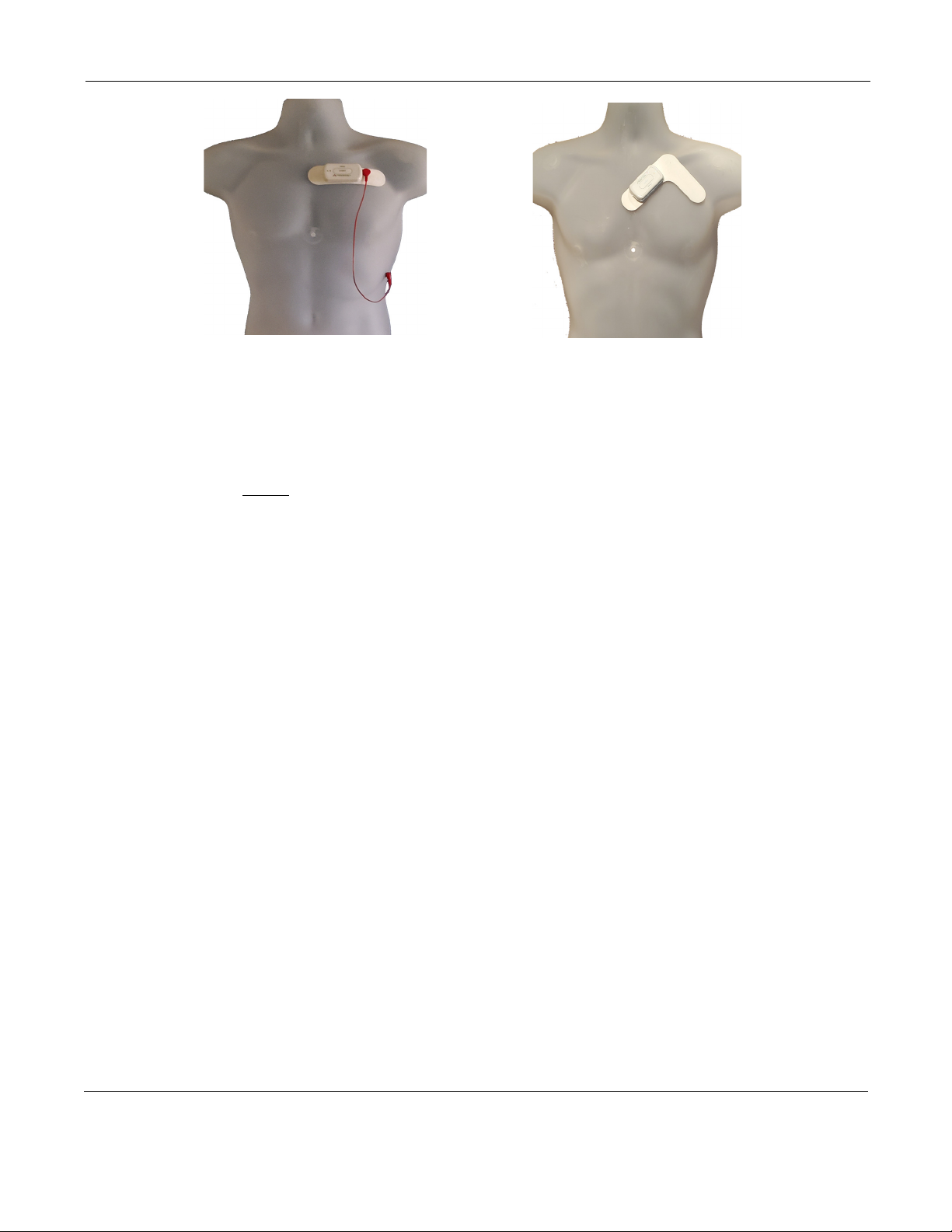
1. There are 3 hook-up options for the DR400:
Select either a 1-lead electrode patch (1CH) for event or Holter, a 1-lead electrode with the addition of
a ECG lead wire (3CH) or a 3-lead patch (3CH)
2. Determine the best location to attach the electrode patch and optional lead wire onto the patient, but
do not attach at this time.
3. Prepare the patient’s skin. If the patient has hair in any of the site, shave it with a safety razor. Use an
alcohol pad and rub the sites briskly until the skin reddens. For best patch adhesion, allow the skin air
dry before proceeding.
NorthEast Monitoring, Inc. NEMM048-Rev-E Page 8 of 20
DR400 User Manual Recording ECG: Step 4: Hook up Patient
Step 4: Hook up Patient
1. Test the DR400 to ensure it is ready for the
next patient. Do this by removing the DR400
from the USB cable, wait for the flashing to
stop, and then quickly pressing the EVENT but-
ton. If the light immediately turns orange, this
means one of two things: 1) the previous
patient’s data has not been erased or 2) it has
been erased and there is no new Patient ID. You
will need to plug the recorder back into the USB
and use the PCPatch utility to delete the file and/
or enter a new Patient ID.
If you have one, you should insert a USB plug at
this time.
2. Attach electrodes to DR400. If using the 1-lead
electrode patch, attach the patch to the DR400.
If you are using the optional lead wire, attach it
to the patch now. Press down firmly so that all
snaps are locked in place.
3. Attach DR400 to Patient. Once the electrode
patch and optional patient extension lead wire
are attached to the DR400, remove paper back-
ing from electrodes and press firmly on to
patient to attach. Once the patch is in place,
attach an electrode to the extension lead wire
and attach to the patient in the proper location.
4. PCPatch Utility. If you want to observe lead
quality at hook-up, start the PCPatch utility if
not already running. Once the PCPatch utility
finds the Bluetooth USB and is “waiting for
DR400”, the utility is ready for you to start the
DR400 recorder.
Step 5: Start Recording
1. To start the DR400 recorder, hold the “EVENT”
button down firmly until the green light goes
off. At the beginning of a new procedure, the
DR400 first shows a solid green light which
goes off when recording has started. You can tell
it has started when:
•The DR400 will flashes green for 30 seconds
(v5.04) or 60 minutes (v5.06)
•If the PCPatch is on and the DR400 has been
paired with the local Bluetooth, the ECG
viewer will automatically open and you will
be able to view the ECG.
Warning: If the light on the DR400 turns a
solid orange, this means that the previous
patient’s data is still on the DR400 or the
DR400 does not have a Patient ID. When this
occurs, you must plug the DR400 into the PC
and use the PCPatch utility to save and/or
delete the previous patient’s data and/or enter a
new Patient ID.
2. Advise the patient that showering is allowed
with the DR400 and patch attached, but we do
not recommend that the patient go swimming or
bathing while wearing either.
3. Instruct the patient on how to use the EVENT
button to indicate symptomatic events or activi-
ties of interest during the Holter test. Advise
them to push the EVENT button briefly.
4. Provide the patient with instructions on how to
use and change the patch and electrode for
patient extension lead wire.
1-lead electrode patch with
optional lead wire (3CH)
3-lead patch placement

NorthEast Monitoring, Inc. NEMM048-Rev-E Page 9 of 20
DR400 User Manual Recording ECG: Step 6: Copy Holter file
Wireless Event
For Event recording, the patient must also be sent
home with a NorthEast Monitoring Gateway that is
set up to transmit events wirelessly and a USB charger
with instructions to charge the DR400 about every 7
days. Let the patient know that the DR400 will flash
orange while charging, and then flash green when
fully charged.
When the recorder is in Event mode, the recording
will restart if the DR400 is erased or the recorder has
been plugged in for > 48 hours.
More information on Event Settings and pairing the
DR400 with the Gateway can be found in the next
Chapter.
Step 6: Copy Holter file
1. After recording is finished and the patch and lead
wire have been removed from the DR400, plug the
recorder into the USB cable that is attached to the
PC where the PCPatch utility is installed.
Note: For Holter, recording stops once the
DR400 is plugged into the USB cable for 2 min-
utes.
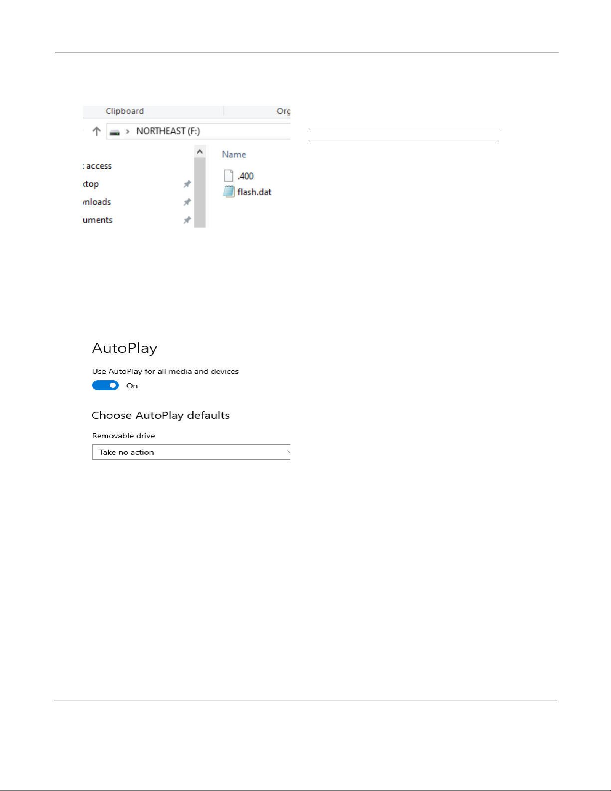
2. Start the PCPatch utility and copy the flash.dat file
(ECG data file). When doing a copy, the utility
will automatically find the next open patient direc-
tory in HE/LX Analysis.
3. Once copied, you may want to erase the file from
the recorder.
4. Remove the DR400 from the PC USB. At this
point plug the DR400 into a power source to
recharge the battery for its next use.
NorthEast Monitoring, Inc. NEMM048-Rev-E Page 10 of 20
Chapter 3 -The PCPatch Utility
The DR400 uses the PCPatch utility to save ECG patient data to HE/LX Anal-
ysis, enter patient IDs, and update settings on the recorder. The utility can also
be used to view your patients ECG data live via a Bluetooth USB that is
attached to the computer.
Download and Install the utility
Go to the NorthEast Monitoring web-site at www.nemon.com to download the PCPatch utility.
Select either the “Analysis” or “Remote” version, based upon your application.
Once downloaded, install the PCPatch on the computer where the HE/LX Analysis or LX
Remote software resides. The default directory, “c:\nm\bin” or “c”\nm\Remote” is where the
PCPatch utility will be installed, unless you specify otherwise. If your HE/LX Analysis or LX
remote software is located in a different directory, you will need to override the “nm” directory
at install. Once installed, you should see a shortcut on your desktop. Click on the shortcut to run
the PCPatch utility.
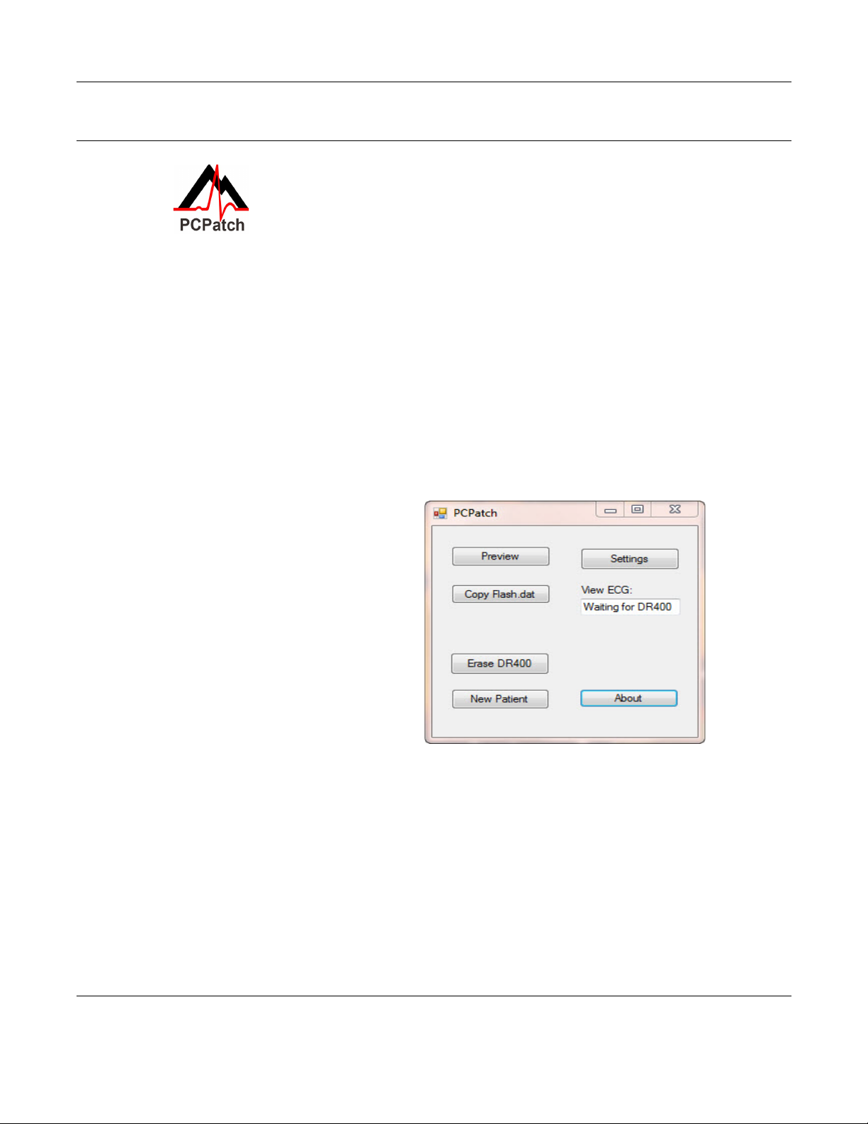
Using the PC Patch Utility
Plug the DR400 into the USB on the same
PC where the PCPatch utility is running.
When the recorder shows a solid green
light, it is ready to communicate with the
PC. When the PCPatch is running will see
the main screen., and when the DR400 is
found, you can do the following:
•Preview - When a patient file is on the
DR400, you can view the Recorder S/N,
the Patient ID and the date and start time
of the recording
•Copy Flash.dat - When recording com-
plete, save the patient file to the patient
directory. The PCPatch will automati-
cally select the next empty patient direc-
tory to save the file to.
•Erase DR400 - After the patient file is
saved, use this to erase the patient file from the recorder. You will need to do this before you
can start a new recording
•New Patient - After erasing previous patient, enter the Patient ID for the next recording
•Settings - Update the Recorder settings and pair with Bluetooth and/or Gateway
DR400 Date and Time. When the data on the DR400 is erased using the PCPatch utility, the
date and time on the recorder will be updated to match the date and time on the PC. After eras-
ing, you can view the date/time on the right-hand side of the PCPatch Settings screen.
PCPatch main screen with Bluetooth available
NorthEast Monitoring, Inc. NEMM048-Rev-E Page 11 of 20
DR400 User Manual The PCPatch Utility: DR400 Settings
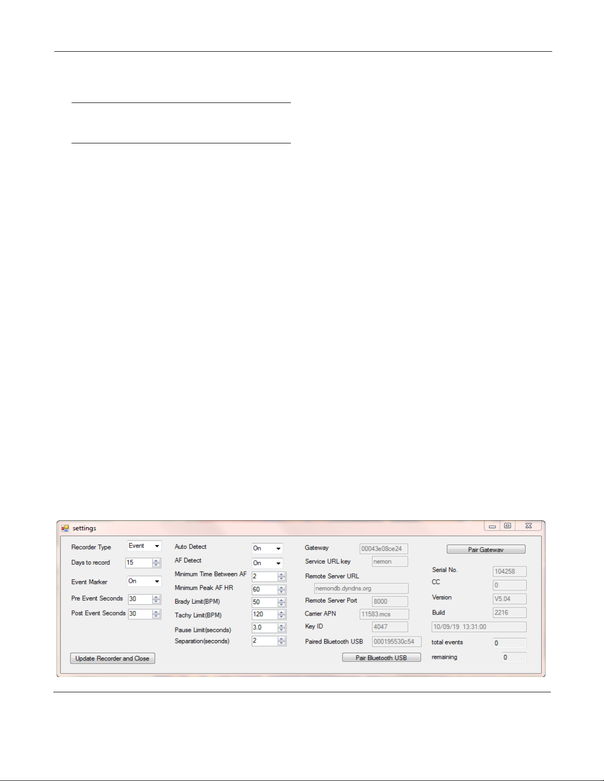
DR400 Settings
Use the PCPatch utility to update the DR400 settings:
Note: For DR400 version 5.03, only Holter recording
and Bluetooth are enabled. For version 5.04 and
greater, Event settings and Gateway are available.
Recorder Type. Holter will record up to 3-channels,
Event will record 1-channel.
Days to record. Stops recording after the number of
days. For Holter, up to 14 days and for Event, 30 days is
recommended regardless of the procedure length.
Event Marker. When “On”, the ECG will be labeled
with one second of 6-cycle square wave at the event.
Event Settings
Are enabled when Recorder Type = Event.
Pre Event Seconds. Number of seconds saved before
the EVENT button is pressed or an automatic event is
detected. Up to 240 seconds allowed.
Post Event Seconds. Number of seconds saved after
the event. Up to 240 seconds allowed.
Auto Detect Settings for Event
Auto Detect Turn auto detection On/Off for all event
types, including AF.
AF Detect. Turn Atrial Fibrillation detection On/Off.
Minimum Time Between AF. For AF events only.
The range of 2 - 90 minutes.
Minimum Peak AF HR. Minimum HR that at least 3
beats of the previous 20 must exceed, in order for an
event to be called AF. The range is 60 - 120 BPM.
Brady Limit. If a heart rate on or below this number is
detected, a brady event will be recorded. The range is
20 - 100 BPM.
Tachy Limit. If a heart rate on or above this number is
detected, a tachy event will be recorded. The range is
50 - 300 BPM.
Pause Limit. If no heart beat is detected for at least the
pause length in seconds, a pause event will be recorded.
The range is1.0 to 10.0 seconds.
Separation. Limits the number of events by type by
requiring a minimum amount of time between the same
type of event. Applies to all events, except AF. The
range is 2 - 20 minutes.
Update Recorder and Close. Click to save changes.
Close window to make no changes.
About the DR400
The following items are about the DR400 and cannot be
updated via the PCPatch: Serial No. of DR400 recorder,
CC (Customer Code), Version number of firmware on
DR400, and Build number of firmware on DR400
Date and Time . The current date and time are auto-
matically updated when the DR400 is erased using the
PCPatch utility.
PCPatch Settings Screen
NorthEast Monitoring, Inc. NEMM048-Rev-E Page 12 of 20
DR400 User Manual The PCPatch Utility: To View Live Patient ECG
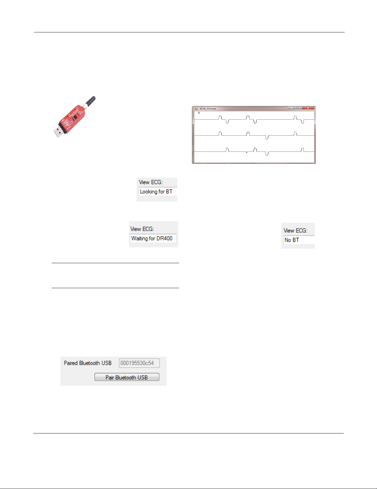
To View Live Patient ECG
The DR400 transmits a Bluetooth signal for ECG
viewing. When the PCPatch is running and receives
the Bluetooth signal, it will open an ECG Viewer
screen. You must have a the Bluetooth USB adapter
pictured below to view the patient ECG on the PC.
First, install Bluetooth USB.
Plug the Bluetooth USB into
the same PC where the
PCPatch utility is installed. It
may take a short time for the
Bluetooth USB driver to be
installed onto the PC. Once
installed and functional, the mode button on the
Bluetooth USB will flash green.
Second, start the PCPatch utility.
Upon starting the PCPatch, you
will first see “Looking for BT”
while the utility searches for a
Bluetooth USB that is physically
attached to the PC.
When the PCPatch Utility is
running and the Bluetooth
USB is found and ready to
receive a signal, you will see
the message, “Waiting for DR400”.
Note: The PCPatch utility only searches for the
Bluetooth USB at start up or while attempting to
pair with a DR400.
Third, pair the DR400 to Bluetooth USB. Before
you can view live ECG with a particular DR400,
you will first need to pair the DR400 with your
Bluetooth USB. On the PC where the Bluetooth
USB is installed, plug in the DR400, open the
PCPatch, and go to the Settings screen. Click on the
“Pair Bluetooth USB” and the PCPatch will attempt
to pair the two. Once paired, you will see the USB
number on the Settings screen. The last 5 numbers
should match the Serial Number of your Bluetooth
USB. The button is only enabled when a Bluetooth
USB was found when the PCPatch utility started.
Using PCPatch to View ECG
With the DR400 ready to record and attached to the
patient, start the PCPatch application. Once the util-
ity shows “Waiting for DR400”, hold the EVENT
button down to start the recording. Once the green
light turns from solid to flashing, recording has
begun and transmits Bluetooth for about 15 sec-
onds. After a brief pause, the PCPatch utility should
open the window to view ECG.
If recording has already started and you wish to
view the ECG, hold the button down until it starts
flashing green rapidly, and then release.
Troubleshooting
No Bluetooth “No BT” message:
•If the Bluetooth USB is
installed on the same computer,
and the PCPatch fails to see it,
you can try to restart the PCPatch so that it
searches again. The PCPatch only searches for
the Bluetooth USB at start up.
•Unplug and reinsert Bluetooth USB. Check to
make sure that the mode light is flashing green.
Restart the PCPatch utility to restart the search.
•Drivers for the Bluetooth USB were included
with your Windows Operating System. But if
you plug in the Bluetooth USB for the first time
and the PC is unable to see it at all (the mode
light on the USB is not flashing green), you may
need to locate and reinstall the device drivers.
“Waiting for DR400” message:
If you see this message and the DR400 appears
to be transmitting but you have no ECG screen,
perhaps the DR400 is not paired with the Blue-
tooth USB that is plugged into the PC. If you
want to fix this now, you will need to remove
the DR400 from the patch electrode and plug it
into the USB cable to pair it with the Bluetooth
USB from the Settings screen.
ECG Viewer (test data shown)
NorthEast Monitoring, Inc. NEMM048-Rev-E Page 13 of 20
DR400 User Manual The PCPatch Utility: Technical Considerations
Microsoft File Explorer keeps opening when
DR400 plugged in
If the window keeps opening, it may be that your
connection is loose. But if you want to prevent the
window from opening when you first plug in or
erase your DR400, you can adjust your Windows
Settings. Go to Settings > Devices >AutoPlay and
for Removable Devices, set it to “Take no action”.
.
Technical Considerations
LX Remote Installations
A special version of the PCPatch utility must be
used with LX Remote to copy the patient files. Yo u
must install the PCPatch Utility on the PC where
the LX Remote desktop application exists. The
installation will default to the c:\nm\Remote direc-
tory.
Once the DR400 file is copied to the LX Remote
directory, you should open the Patient Information
window in LX Remote and enter the patient infor-
mation before sending the file.
Network Installations
For Holter, if the PCPatch utility is being installed
on a PC that does not have HE/LX Analysis
installed, you will need to do the following to allow
the user to save patient files to HE/LX Analysis:
1. Ensure that the local PC has read/write access to
the HE/LX Analysis patient directory on the
server
2. On the local PC, create a directory labeled
“c:\nm\bin”
•Copy the h4w.ini file from a PC that has HE/LX
Analysis installed and paste it into the local
directory. (The h4w.ini file most likely can be
found in the c:\nm\bin directory.)
Using Windows, test to ensure that the path to the
Patient Directory works for the PC where PCPatch
is installed.
NorthEast Monitoring, Inc. NEMM048-Rev-E Page 14 of 20
DR400 User Manual The PCPatch Utility: Wireless Event Recording
Wireless Event Recording
Event recording on the DR400 is done wirelessly,
via a NorthEast Monitoring Gateway and the
Socket software. Refer to the Gateway - Socket
Technical Manual, NEMM046, for more informa-
tion on how to set up and run the Wireless feature.
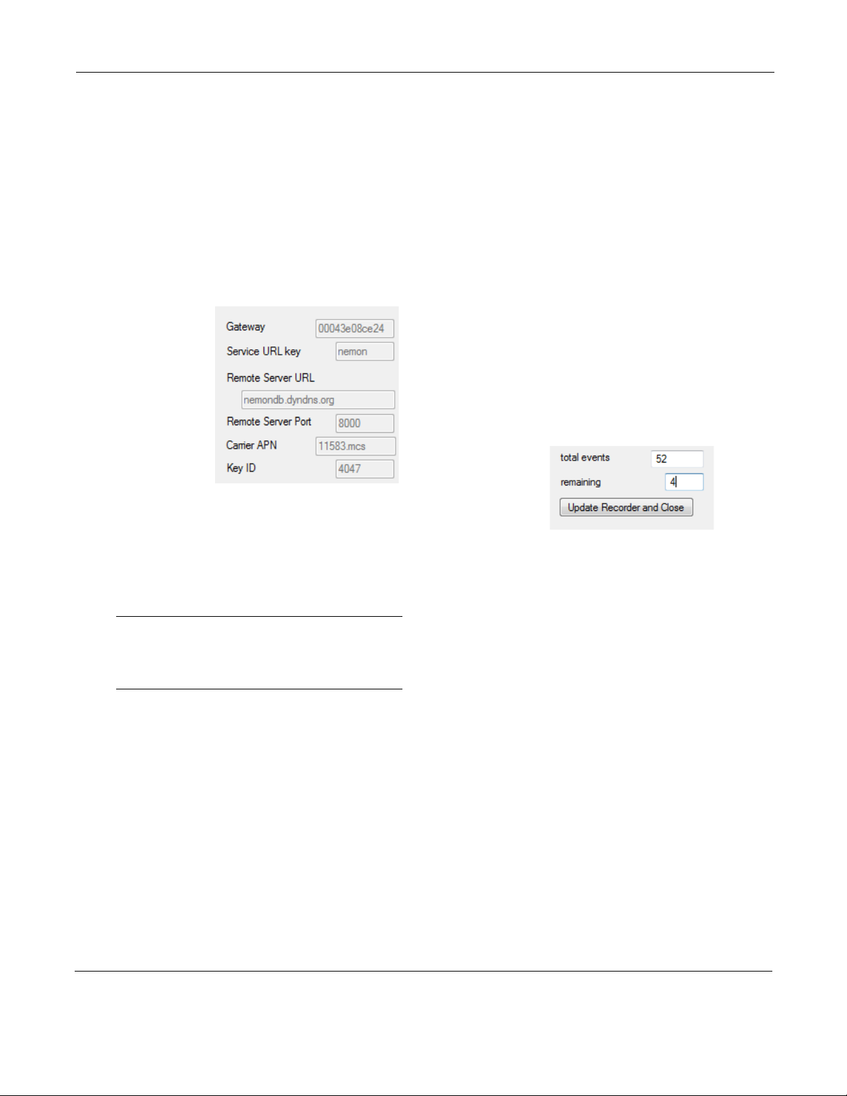
The Gateway Settings
The Gateway field on the Settings screen shows
which Gateway has been paired with the DR400.
The Service
URL key,
Remote Server
URL, Remote
Server Port,
Carrier APN,
and Key ID are
all required to
transmit suc-
cessfully.
If any of these
items are blank or incorrect, you can update these
by putting your URLKEY.dat file into the bin direc-
tory and pairing the Gateway again. If your
URLKEYdat is incorrect or you do not have a
URLKEYdat file, contact NorthEast Monitoring or
your distributor for assistance.
Important: A URLKEY.dat file must exist in your
directory in order to pair with a new Gateway. If
the file does not exist, the Pair Gateway button will
not be enabled.
Recording an Event Procedure
The setup and recording procedure are the same as
Holter and are described in the previous chapter.
While recording in Event mode, the patient should
charge the DR400 about every 7 days. Remind the
patient that he recorder will flash orange while
charging, and then flash green when fully charged.
Up to 30 days of event recording is possible in a
single event procedure.
As with Holter, the patient can record an event by
pressing the EVENT button quickly. The recorder
will flash green when recording an event. Flashing
will also occur when the recorder is saving an auto-
matically generated event.
Once an event has been saved, the DR400 will
attempt to contact the Gateway every 20 minutes
for the first hour, and then once an hour after that.
Once contact is made with the Gateway, all events
will be transmitted and the process will begin again
when a new event is saved.
Transmit Events Manually
With the Gateway present and the Socket software
running, hold the EVENT button down for about 10
seconds. Once the DR400 starts flashing rapidly,
release the button, and the DR400 will to transmit
to the paired Gateway. This can be done during of
after the procedure has stopped.
Events on returned DR400
After the event pro-
cedure, the Settings
screen will show
you the total number
of events that were
saved as well as any
that are still remain-
ing and not transmitted. If you would like to save
the remaining events, you will need to plug in the
Gateway and transmit the events manually as
described above.

NorthEast Monitoring, Inc. NEMM048-Rev-E Page 15 of 20
Chapter 4 -Appendices
Appendix A: Maintenance and Care of the Recorder
Clean the outside of the recorder with a damp soft cloth between uses; use water and a non-abra-
sive liquid soap, as required. DO NOT use any abrasive cleaners, such as acetone, on the outside
of the recorder.
Disinfect as needed, following instructions from your infection control department. Sani-Cloth
germicidal surface wipes are recommended.
Sterilization is not needed.
Do not submerge the recorder in water.
At the end of their useful lives, all NorthEast Monitoring Inc. products should be disposed of
following local ordinances.
Appendix B: Pacemaker Detection
The recorder has a built-in pacemaker detection capability. This was designed to overcome the
problems inherent with the analysis of Holter recordings from patients with pacemakers.
A pacemaker is designed to initiate cardiac conduction by stimulating a spot on the myocardium
with a pulse of 1-4 volts and a duration of typically 250 to 2,000 microseconds. When this pulse
is seen at the surface recording electrodes it is significantly attenuated. For patients with a uni-
polar electrode configuration, the signal at the surface may range from under 50 to over 200
millivolts. When a bipolar lead configuration is used, the signal is typically much lower and is
in the range of 3 to 50 millivolts. Especially with the bipolar leads, the signal size is dependent
on the positions of the pacemaker lead and the surface electrodes.
The amplitude of the signal being referred to here is not the size of the "spike" commonly seen
on an ECG cart or bedside monitor. Since the duration of the pulse is short compared to a QRS
complex, normal ECG recorders will greatly attenuate the signal; in some cases it cannot be
seen at all. Also, some ECG recorders have devices which enhance the pace pulse to insure that
it will be displayed. Only very wide bandwidth recorders as are sometimes used in an electro-
physiology study will show the unmodified full amplitude of the pulse.
The recorder has the wide bandwidth ECG amplifiers necessary to pass the pacemaker pulse.
Since the pulse would still be too short to be recorded in a reliable manner at any practical sam-
pling rate for Holter recording, the pulse is detected by the recorder. The time of the pulse is
then digitally stored along with the Holter ECG data. When the data is analyzed, the pacemaker
pulse is displayed and used for the analysis.

NorthEast Monitoring, Inc. NEMM048-Rev-E Page 16 of 20
DR400 User Manual Appendices: Appendix C: Accessories
At recording time, it is desirable to have the
recorder be as sensitive to the pacemaker pulse as
possible so pulses will not be missed. A conflicting
requirement is that there should be as few false
pacemaker detections as possible.
False pacemaker detections are primarily caused by
electrical events. Any external electrical signal that
is coupled to the patient electrodes which looks like
a pacemaker pulse will of necessity be stored by the
recorder. The most common form of electrical sig-
nal that can look like a pacemaker signal is an elec-
trostatic discharge (ESD) or "spark." These happen
very frequently in dry weather but also occur, at a
lower rate, under humid conditions.
Fortunately most ESD spikes as seen at the patient
electrodes are of shorter duration or of lower ampli-
tude than the real pacemaker pulses. While there is
no absolute limit to the size or duration of the ESD
pulses, the recorder ignores all pulses that are less
than 150 micro-seconds long or are less than two
millivolts in size.
As pacemakers are normally programmed to a pulse
width greater than 200 microseconds, this does not
cause a loss of detection. The requirement that the
pacemaker pulse be at least two millivolts in size is
not a common problem.
Appendix C: Accessories
Contact your distributor to purchase accessories for
the DR400.
NEMEL002. 1-lead electrode patch
NEMEL003. 3-lead electrode patch
NEMCA161. 16” Reusable patient extension lead
wire (use with NEMEL002 for 3-channel record-
ing)
NEMP00511. USB Power Port Adapter LV Sun
with 3’ power cord.
NEMP00513. Sena Parani Mfg PN SD1000U:
Bluetooth USB Adapter for Serial Port
Appendix D: Extraction of
ECG data on 3-channel
It is possible to retrieve the raw ECG files from the
Holter files. For all 3-channel data, the process
results in three files, one for each channel. Each file
is then in the form of a binary file consisting of 16-
bit words (little endian) with each word represent-
ing one sample. The sampling is at 180 samples per
second. The data is scaled so that the least signifi-
cant bit has a value of 12.5 uv. If a pacemaker pulse
was detected, the sample at the time of detection
will be replaced by the value 0x8000.
To generate these files, first analyze the data (actu-
ally the flash.dat) from the recorder using any com-
patible version of the LX Analysis program. At the
completion of this there will be a file "datacard.dat"
in the patient directory. The full path is by default:
c:\nm\pat\xx\datacard.dat
where xx is the number of the patient dataset.
This can be seen in the "No. and Directory" col-
umns of the "File->open/new" display.
Then, change the directory to c:\nm\bin and on a
single command line, run the following command
using the following 5 arguments:
unpackc d1 f1 f2 f3 0
•where d1 is the path to the source datacard file,
for example,
d1= c:\nm\pat\xx\datacard.dat
•f1, f2 and f3 are the resultant binary destination
files, for example:
f1 = c:\nm\pat\xx\flashc0.dat
f2 = c:\nm\pat\xx\flashc1.dat
f3 = c:\nm\pat\xx\flashc2.dat
The result will be the three files in the patient direc-
tory xx described previously. The files are
flashc0.dat flashc1.dat and flashc2.dat which are for
channel 1,2 and 3 respectively. If desired, the desti-
nation paths for this command can be any other
path but spaces are not allowed in the path or file
name.

NorthEast Monitoring, Inc. NEMM048-Rev-E Page 17 of 20
DR400 User Manual Appendices: Appendix E: EMC Information
Appendix E: EMC Information
Attention should be paid to the following EMC
information prior to installing or using the
Northeast Monitoring DR400 Recorder device.
• Portable and mobile Radio Frequency
(RF) communication equipment may
interfere with the operation of the device.
• The device has been tested and found to
comply with IEC/EN 60601-1-2.
• Computers, cables and accessories not
tested to 60601-1-2 may result in increased
emissions or decreased immunity of the
device.
• Verify normal operation if utilizing the
device adjacent to or stacked with other
electrical equipment.
Guidance and manufacturer’s declaration – electromagnetic emissions
The Northeast Monitoring DR400 Recorder is intended for use in the electromagnetic environment
specified below. The customer or user of the Northeast Monitoring DR400 Digital Recorder should ensure
that it is used in such an environment.
Emissions Test Compliance Electromagnetic environment –
guidance
RF emissions CISPR 11 Group 1 Northeast Monitoring DR400
Digital Recorder uses RF energy
only for its internal function.
Therefore, its RF emissions are
not likely to cause any in nearby
electronic equipment.
RF emissions CISPR 11 Class B Northeast Monitoring DR400 Dig-
ital Recorder is suitable for use in
all establishments other than
domestic and those directly con-
nected to the public low-voltage
power supply network that sup-
plies buildings used for domestic
purposes.
Harmonic emissions
IEC 61000-3-2
Not applicable
Voltage Fluctuations/flicker
emissions IEC 61000-3-3
Not applicable

NorthEast Monitoring, Inc. NEMM048-Rev-E Page 18 of 20
DR400 User Manual Appendices: Appendix E: EMC Information
Guidance and manufacturer’s declaration – electromagnetic immunity
The Northeast Monitoring DR400 is intended for use in the electromagnetic environment specified
below. The customer or user of the recorder should ensure that it is used in such an environment.
Immunity test IEC 60601 test
level
Compliance level Electromagnetic
environment – guidance
Electrostatic discharge
(ESD) IEC 61000-4-2
± 6kV contact
± 8kV air
± 6kV contact
± 8kV air
Floors should be wood,
concrete or ceramic tile.
If floors are covered with
synthetic material, the
relative humidity should be
at least 30%.
Electrical fast
transient/burst
IEC 61000-4-4
± 2 kV for power
supply lines
± 1 kV for input/
output lines
Not applicable.
No cables exceed 3
meters
Mains power quality
should be that of a typical
commercial or hospital
environment.
Surge
IEC 61000-4-5
± 1 kV line(s) to
line(s)
± 2 kV line(s) to
earth
Not applicable.
Northeast Monitoring
DR400 Recorder is
battery powered.
N/A
Voltage dips, short
interruptions and
voltage variations on
power supply input
lines
IEC 61000-4-11
< 5% UT
(>95% dip in UT)
For 0,5 cycle
40% UT
(60% dip in UT)
For 5 cycles
70% UT
(30% dip in UT)
for 25 cycles
< 5% UT
(>95% dip in UT)
for 5 s
Not applicable.
Northeast Monitoring
DR400 Recorder is
battery powered.
N/A
Power frequency (50/
60 Hz) magnetic field
IEC 61000-4-8
3 A/m 3 A/m Power frequency
magnetic fields should be at
levels characteristic of a
typical location in a typical
commercial or hospital
environment.
NOTE UT is the a.c. mains voltage prior to application of the test level.
NorthEast Monitoring, Inc. NEMM048-Rev-E Page 19 of 20
DR400 User Manual Appendices: Appendix E: EMC Information
Guidance and manufacturer’s declaration – electromagnetic immunity
The Northeast Monitoring DR400 Recorder is intended for use in the electromagnetic environment specified
below. The customer or user of the recorder should ensure that it is used in such an environment.
Immunity test IEC 60601 test
level
Compliance
level
Electromagnetic environment – guidance
Conducted RF
IEC 61000-4-6
Radiated RF
IEC 61000-4-3
3 Vrms
150 kHz to 80 MHz
3 V/m
80 MHz to 2,5 GHz
3 V
3 V/m
Portable and mobile communications equipment
should be used no closer to any part of the
Northeast Monitoring DR400 Recorder, including
cables, than the recommended separation
distance calculated from the equation applicable
to the frequency of the transmitter.
Recommended separation distance
d = 1.2
P
d = 1.2
P 80 MHz to 800 MHz
d = 2.3
P 800 MHz to 2.5 GHz
Where P is the maximum output power rating of
the transmitter in watts (W) according to the
transmitter manufacturer and d is the
recommended separation distance in metres (m).
Field strengths from fixed RF transmitters, as
determined by an electromagnetic site survey,a
should be less than the compliance level in each
frequency range.b
Interference may occur in the vicinity of
equipment marked with the following symbol:
NOTE 1: At 80 MHz and 800 MHz, the higher frequency range applies
NOTE 2: These guidelines may not apply in all situations. Electromagnetic propagation is affected by
absorption and reflection from structures, objects and people.
a Field strengths from fixed transmitters, such as base stations for radio (cellular/cordless)
telephones and land mobile radios, amateur radio, AM and FM radio broadcast cannot be
predicted theoretically with accuracy. To assess the electromagnetic environment due to fixed RF
transmitters, an electromagnetic site survey should be considered. If the measured field strength
in the location in which the recorder is used exceeds the applicable RF compliance level above,
the recorder should be observed to verify normal operation. If abnormal performance is observed,
additional measures may be necessary, such as re-orienting or recorder
b Over frequency range 150 KHz to 80 MHz, field strengths should be less than 3 V/m.
NorthEast Monitoring, Inc. NEMM048-Rev-E Page 20 of 20
DR400 User Manual Appendices: Appendix E: EMC Information
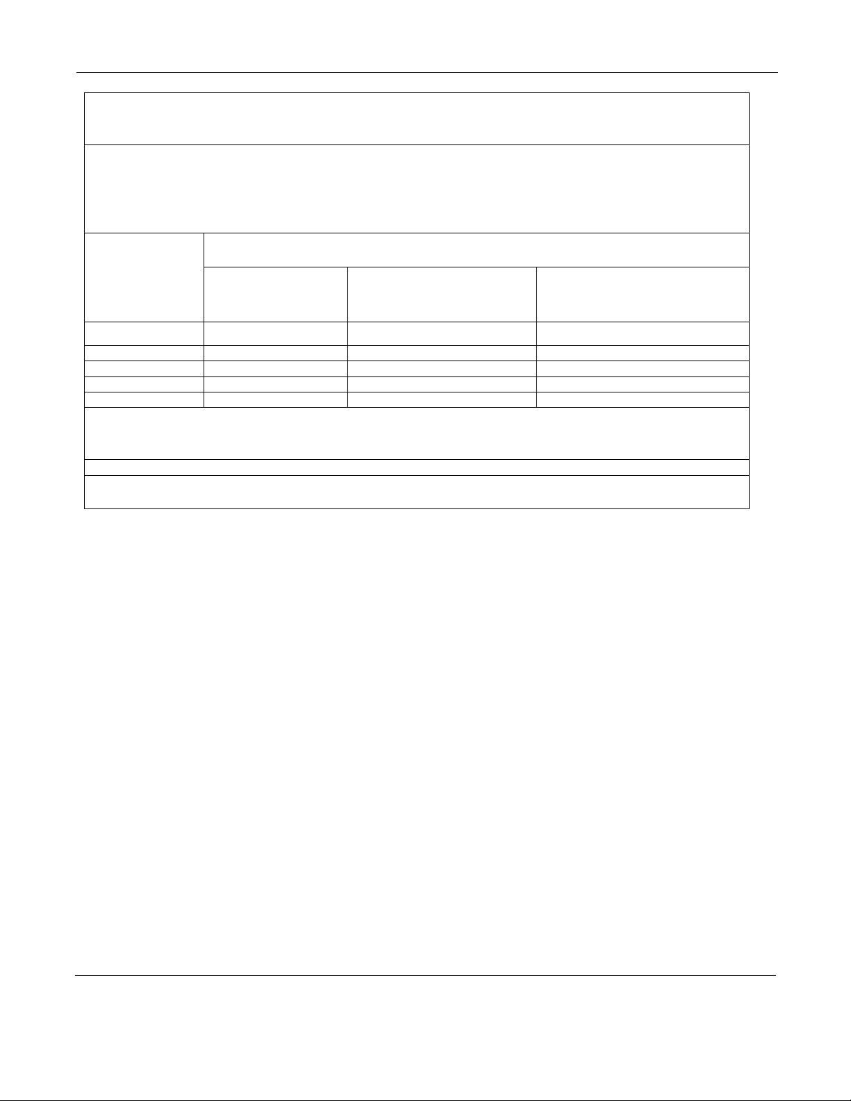
Recommended separation distances between portable and mobile RF communications equipment
and the Northeast Monitoring DR400 Digital Recorder
The Northeast Monitoring DR400 Digital Recorder is intended for use in the electromagnetic environment
in which radiated RF disturbances are controlled. The customer of the user of the recorder can help
prevent electromagnetic interference by maintaining a minimum distance between portable and mobile RF
communications equipment (transmitters) and the recorder as recommended below, according to the
maximum output power of the communications equipment.
Rated
maximum
output power of
transmitter
W
Separation distance according to frequency of transmitter
m
150 KHz to 80 MHz
d = 1.2
P
80 MHz to 800 MHz
d = 1.2
P
800 MHz to 2.5 GHz
d = 2.3
P
0.01 0.12 0.12 0.23
0.1 0.38 0.38 0.73
1 1.2 1.2 2.3
10 3.8 3.8 7.3
100 12 12 23
For transmitters rated at a maximum output power not listed above, the recommended separation distance
d in metres (m) can be estimated using the equation to the frequency of the transmitter, where P is the
maximum output power rating of the transmitter in watts (W) according to the transmitter manufacturer.
NOTE 1: At 80 MHz and 800 MHz, the separation distance for the higher frequency range applies.
NOTE 2: These guidelines may not apply in all situations. Electromagnetic propagation is affected by
absorption and reflection from structures, objects and people.
Other manuals for DR400
5
Table of contents
Popular Voice Recorder manuals by other brands


Olympus
Olympus 141927 - VN 4100PC 256 MB Digital Voice... instructions

Lafayette
Lafayette TR-101 manual

Panasonic
Panasonic RRQR240 - IC RECORDER operating instructions

SEFRAM
SEFRAM DAS220 user manual

YOKOGAWA
YOKOGAWA SMARTDAC+ GX10 user manual

Mitsubishi Electric
Mitsubishi Electric DX-TL4516E series Operation manual