Northern Lights TA-258 User manual


Assembly Guide and Owner’s Manual 1
IMPORTANT
Read all assembly instructions and safety precautions; reference all safety guidelines and
warning labels before using this product. Please sa e the instructions afterward for future
reference as the instructions are written for your safety and to protect the unit.
Lisez toutes les instructions de montage et les consignes de sécurité, se référer à toutes les
consignes de sécurité et les mises en garde avant d'utiliser ce produit. Veuillez sauvegarder
les instructions pour référence ultérieure parce que celles-ci sont écrites pour votre sécurité et
pour protéger l'appareil.
SAFETY
Properly warm up and stretch before exercising. If you feel pain or dizziness at any time
while exercising, stop immediately and consult your physician.
Bien réchauffer et étirer avant l'exercice. i vous ressentez une douleur ou des
étourdissements durant votre entraînement, arrêtez immédiatement et consultez votre
médecin.
Obtaining Service
Before proceeding, find your treadmill’s model, serial number located near the on/off power
switch and power cord and enter it in the space pro ided below.
Model:
Serial Number:
Date of Purchased: month
/
date /
year
» Refer to the SERIAL NUMBER and MODEL NAME when calling for ser ice.
SAVE THE INSTRUCTION - THINK SAFETY!
Location of Serial Number

2
Assembly Guide and Owner’s Manual
Important Safety Instructions (English
CAUTION
To reduce the risk of burns, fire of burns, fire, electric shock, or injury to persons,
always unplug the unit from its power source before cleaning it or performing any
maintenance Special care must be taken when adjusting running belt Remove
any loose clothing and tie back your hair Be very careful to keep your fingers and
any other object clear of the belt and rollers, especially in front of the roller and
behind the deck The treadmill will not stop immediately if an object becomes
caught in the belt or rollers
It is the responsibility of the owner to ensure that all users of this equipment are adequately
informed of stated precautions.
Read all instructions and enclosed literature carefully. Understand the assembly and
operation before using the equipment.
Do not operate treadmill on deeply padded, plush or shag carpet. Excessive heating can occur
and cause fire, electric shock, or injury to persons.
The treadmill should never be left unattended when plugged in. Disconnect the treadmill by
turning the power switch to the OFF (O position, and then unplug from outlet when the unit is
not in use, and before putting on or taking off parts.
Close supervision is necessary when this treadmill is used by, on, or near children, invalids, or
disabled persons. Do not allow children, or people unfamiliar with the operation of this
equipment, on or near it.
Keep hands away from all moving parts.
Never operate the treadmill if it has a damaged core or plug, if it is not working properly, if it
has been dropped or damaged, or dropped into water. Return the treadmill to a service
center for examination and repair.
Keep the cord away from heated surfaces.
Do not operate where aerosol (spray products are being used or where oxygen is being
administered.
Keep equipment away from water and moisture. Avoid dropping anything on or spilling
anything inside the equipment to prevent electric shock or damage to the electronics. Do not
operate electrically powered equipment in damp or wet locations.
Never operate the treadmill with the air openings blocked. Keep the air openings free of lint,
hair, and the like.
Never drop or insert any object into any opening.
Do not use outdoors.
To disconnect, turn all controls to the off position, remove tether cord, then remove plug from
outlet.

Assembly Guide and Owner’s Manual 3
Do not attempt to use your treadmill for any purpose other than for the purpose it is intended.
Do not carry this treadmill by supply cord or use cord as handle.
Route power cable so that they are not walked on, pinched, or damaged by items placed upon
or against the, including the equipment itself.
Grounding Instruction
This treadmill must be grounded. If the unit malfunctions or breakdown, grounding provides a path
of least resistance for electric current, which reduce the risk of electric shock. This product is
equipped with a cord having an equipment-grounding conductor and a grounding plug. The plug
must be plugged into an appropriate outlet that is properly installed and grounded in accordance
with all local codes and ordinances.
Grounding methods
DANGER
Improper connection of the equipment-grounding conductor can result in a risk of
electric shock Check with a qualified electrician or serviceman if you are in doubt
as to whether the product is properly grounded Do not modify the plug provided
with the product – if it will not fit the outlet, have a proper outlet installed by a
qualified electrician
Remove tether cord after use to prevent unauthorized treadmill operation
Grounded Outlet
Grounding Pin Grounded Outlet Box
Metal Screw
Adapter
Tab of
Grounding
Screw

4
Assembly Guide and Owner’s Manual
Important Safety Instructions (French
ATTENTION
Afin de réduire le risque de brûlures, de brûlures d’incendie, d'incendie, de choc
électrique ou de blessure, débranchez toujours l'appareil de sa source
d'alimentation avant de le nettoyer ou d'effectuer un entretien. Des précautions
particuli res doivent
ê
êê
ê
tre prises lors de l'ajustement du tapis de course. Retirez
tous vêtements lâches et attachez vos cheveux. Soyez tr s prudent pour garder vos
doigts et tout autre objet hors de la courroie et galets, surtout devant le rouleau et
derri re le pont. Le tapis ne s'arrête pas immédiatement si un objet se fait prendre
dans la courroie ou galets.
Il est de la responsabilité du propriétaire de s'assurer que tous les utilisateurs de cet
équipement soient dûment informés des précautions indiquées.
Lisez toutes les instructions et la documentation jointe en annexe. Comprenez le montage et le
fonctionnement avant d'utiliser l'équipement.
Ne pas faire fonctionner le tapis roulant sur un tapis rembourré profondément, en peluche ou
longs poils. Une chaleur excessive peut se produire et provoquer un incendie, un choc
électrique ou des blessures corporelles.
Le tapis ne doit jamais être laissé sans surveillance lorsqu'il est branché. Banchez le tapis en
tournant l'interrupteur d'alimentation en position OFF (O , puis débranchez la prise de courant
lorsque l'appareil n'est pas en cours d'utilisation, et avant de mettre ou d'enlever des pièces.
Une surveillance étroite est nécessaire lorsque ce tapis de course est utilisé par, sur ou près des
enfants, les invalides ou handicapés. Ne laissez pas les enfants ou les personnes qui ne
connaissent pas le fonctionnement de cet équipement, y courir ou rester à proximité.
Gardez les mains éloignées des pièces en mouvement.
Ne faites jamais fonctionner le tapis s’il possède un noyau ou une fiche endommagé, s'il ne
fonctionne pas correctement, s'il a échappé ou endommagé ou s'il est tombé dans l'eau.
Remettrez le tapis à un centre de service pour examen et réparation.
Gardez le cordon éloigné des surfaces chaudes.
Ne pas l’utiliser à l’endroit où les produits aérosols (vaporisateurs sont utilisés ou où de
l'oxygène est administré.
Gardez l'équipement loin de l'eau et de l'humidité. Evitez de laisser tomber quoi que ce soit sur
ou renverser quelque chose à l'intérieur de l'appareil pour éviter un choc électrique ou
d'endommager l'électronique. Ne faites pas fonctionner l'équipement électrique dans des
endroits humides ou mouillés.
Ne faites jamais fonctionner le tapis avec les ouvertures de ventilation obstruées. Gardez les
ouvertures d'air hors de peluches, de cheveux, etc.
Ne jamais laisser tomber ou insérer un objet dans les ouvertures.

Assembly Guide and Owner’s Manual 5
Ne pas l’utiliser à l'extérieur.
Pour débrancher, mettez toutes les commandes à la position d'arrêt, débranchez le cordon
d'attache, puis retirez la fiche de la prise.
N'essayez pas d'utiliser votre tapis roulant à toute autre fin autre que l'usage auquel il est
destiné.
Ne transportez pas ce tapis de course par le cordon d'alimentation ou utiliser le cordon comme
poignée.
Fixez les câbles d'alimentation de sorte qu'ils ne sont pas piétinés, ni pincés ou endommagés
par des objets placés sur ou contre le tapis, y compris l'équipement lui-même.
Instruction de mise à terre
Ce tapis roulant doit être mis à terre. En cas de dysfonctionnement ou d'une panne de l’appareil la
mise à terre fournit un chemin de moindre résistance au courant électrique, ce qui réduit le risque
de choc électrique. Ce produit est équipé d'un cordon muni d'un conducteur de terre et une fiche de
mise à terre. La fiche doit être branchée dans une prise appropriée qui est correctement installée et
mise à terre conformément à tous les codes et règlementation locaux.
Méthodes de mise à terre
DANGER
Un branchement incorrect du conducteur de mise à terre peut entraîner un risque de choc
électrique. Vérifier avec un électricien qualifié si vous avez des doutes quant à savoir si le
produit est correctement mis à terre. Ne modifiez pas la fiche fournie avec le produit - si elle
n'entre pas dans la prise, faites installer une prise adéquate par un électricien qualifié.
Retirez le cordon coupe après chaque utilisation pour éviter tout fonctionnement non autorisé du
tapis roulant
Grounded Outlet
Grounding Pin Grounded Outlet Box
Metal Screw
Adapter
Tab of
Grounding
Screw

6
Assembly Guide and Owner’s Manual
Table of Contents
Obtaining Service ………………………………………………………………………………………. 1
Important Safety Instructions (English/French) …………………………….……….…… -5
Table of Contents ……………………………………………………….………….……..…..…..…..
6
Assembly Guide (English / French) …………………..……………..……………………….… 7-15
Parts List ……………………………………………………………………………………………….……………....…..… 9
E ploded View ………………………………………………………………………….……………………………….…. 10
Assembly Steps ………………………………………………………………………………………………………….…. 11-15
Console Display Information …………………………………….………..………….……….…. 16- 1
LCD display……………………………………………………………………………………………….…..………..…….. 17
Key Pad …………………………………………………………………………………………………….…..….………….. 18
Build-In Programs …………………………………………………………………………………………………………. 19
Program Profile and Default Value Summary ………………………………………………..………………. 19-21
Operate the Treadmill …………………………………………………………………………….……
-31
Getting Started (English) ………………………………………………………………………………………..……….
22
Getting Started (French) …………………………………………………………………………………….…….……. 23
Using Safety Magnetic Stop Key & Clip …………………………………………………………….…….….……
24
Target Heart Rate Zone ……………………………………………………………………………………….……..….. 24
Workout Options …………………………………………………………………………………………………….….…. 25
Quick start e ercising …………………………………………………………………………………………….…..….. 25
Selecting a Program ……………………………………………………………………………………………….….….. 25-26
Selecting a Heart Rate Program & Beginning your Heart Rate Program………………..………... 26-28
Selecting an USER Programs & Starting Workout with USER key ………………………………….… 29-30
The importance of the Warm Up and Cool Down………………………………………………….…….…. 30
Pausing During a Warm Up/Workout/Cool Down period……………………………………….….…… 31
Terminate or Finish your workout………………………………………………………………………….…….… 31
General Maintenance ………………………………………………………………………….………
31-35
Cleaning the treadmill……………………………………………………………………………………………………..
32
Store the Heart Rate Transmitter Chest Strap………………………………………………………..…….…. 32
Tightening the fasteners…………………………………………………………………………………………………. 32
Belt adjustments…………………………………………………………………………………………………………….. 32-33
Troubleshooting …………………………………………………………………………………………..
34-36
Service Check List for Troubleshooting……………………………………………………………………………. 34-35
Troubleshooting Heart Rate Issues ……………………………………..…………………………………………..
35
Troubleshooting Error Codes……………………………………………………………………………………………
36

Assembly Guide and Owner’s Manual 7
Assembly Guide (English)
The unit is shipped in one box. You will need assistance to assemble this unit, especially when
assembling multiple parts or mo ing the equipment. Ask for help from two or more people to
unpack and assemble the treadmill. Do NOT attempt assembly by yourself.
WARNIN
It is very important to follow the assembly instructions correctly and to make sure
all parts are firmly tightened. If the assembly instructions are not followed
correctly, the treadmill could have parts that are not tightened and will seem loose
and may cause irritating noises. To prevent the treadmill from damage, risk of
burns, fire of burns, fire, electric shock, or injury to persons, the assembly
instructions must be reviewed and corrective actions should be taken.
To ensure ease of product assembly, please take time to erify the size and quantities of all
required assembly hardware. Use the itemized parts listing for reference.
The product assembly process has been documented in easy to follow stages. Please read all
assembly instructions carefully. Take time to re iew the manual and familiarize yourself with
the entire assembly process before proceeding.
Use this treadmill only for its intended use as described in this manual. Do not use
attachments not recommended by the manufacturer.
Perform product assembly in a 4ft. x 6ft. flat area.
Note: After assembly is completed, allow a minimal of 2-3ft. of space on each side of the unit
for
user access. Pro ide a minimum of 3
⅟₂
feet clearance between the rear of the treadmill and any
fixed object.
Access to a 100-120 volt, 15-20 ampere grounded outlet for the unit in the following area: USA,
Canada, Japan, and Taiwan (or access to a 220-240 volt, 10-15 ampere grounded outlet in other
countries.)
Do not attempt to disable the grounded plug by using improper adapters, or in any way modify
the core set. A serious shock or fire hazard may result along with computer malfunctions.
Make sure the power switch is OFF and the treadmill is not plugged into a power source.
Do not dispose of any packaging materials until assembly of the product is completed.
Assembly tools are included, but you may also use standard household tools to complete
assembly of this product.
If you plan to mo e the unit, obtain help and lift it properly. Grasp the rear end of the
treadmill. Lift the treadmill and roll it on its front wheels. Do not grasp any other plastic part
while lifting or mo ing the unit. The other plastic parts are not reinforced and they may break.

8
Assembly Guide and Owner’s Manual
Assembly Guide (French)
L'appareil est li ré dans une boîte. Vous a ez besoin d'aide pour assembler cet appareil, surtout
lorsque ous assemblez de pièces multiples ou déplacez l'appareil. Demandez l'aide de deux ou
plusieurs personnes pour déballer et assembler le tapis roulant. Ne tentez pas d'assembler par
ous-même.
AVERTISSEMENT
Il est très important de suivre les instructions de montage et de s'assurer que
toutes les pièces sont bien serrées. Si les instructions de montage ne sont pas
suivies correctement, le tapis peut avoir des parties qui ne sont pas serrées et
semblent bouger et elles pourraient causer des bruits irritants. Pour protéger le
tapis de tous dégâts, risque de brûlures, de brûlures d’incendie, d'incendie, de choc
électrique ou de blessures corporelles, les instructions de montage doivent être
examinées et des mesures correctives doivent être prises.
Pour faciliter l'assemblage du produit, euillez prendre le temps de érifier la taille et la
quantité de tout le matériel d’assemblage requis. Utilisez les pièces détaillées énumérant à
titre de référence.
Le processus d'assemblage du produit a été documentée dans les étapes faciles à sui re.
Veuillez lire toutes les instructions de montage. Prenez le temps de lire le manuel et de ous
familiariser a ec le processus d'assemblage a ant de procéder.
Utilisez ce tapis de course uniquement pour son usage pré u, comme décrit dans ce manuel.
N’utilisez pas d'accessoires non recommandés par le fabricant.
Effectuez l'assemblage du produit dans unede surface plane 4x6 pi.
Remarque: Après a oir terminé l'assemblage, laissez un minimum de 2-
3pi d'espace de chaque
côté de l'unité d'accès utilisateurs. Fournir un minimum de 3 ⅟₂ pieds de dégagement entre
l'arrière du tapis roulant et tout autre objet fixe.
L'accédez à une prise mise à terre de 100-120 volt, 15-20 ampères dans les domaines sui ants:
USA, Canada, Japon et Taïwan (ou accédez à une prise mise à terre de 220-240 volt, 10-15
ampères dans d'autres pays. )
Ne tentez pas de désacti er la prise de terre à l'aide d'adaptateurs inappropriés, ou en aucune
façon modifier le jeu de base. Une décharge ou un incendie peut entraîner des
dysfonctionnements a ec l'ordinateur.
Assurez- ous que l'interrupteur d'alimentation est sur OFF et que le tapis roulant n'est pas
branché à une source d'alimentation.
Ne jetez pas le matériel d'emballage jusqu'à ce que l'assemblage du produit soit terminé.
Les outils de montage sont inclus, mais ous pou ez également utiliser des outils ménagers
standards pour terminer l'assemblage de ce produit.

Assembly Guide and Owner’s Manual 9
Si vous prévoyez de déplacer l'appareil, obtenez de l'aide et soulevez-
le correctement Saisissez
l'extrémité arrière du tapis roulant
Soulevez le tapis roulant et le rouler sur ses roues avant Ne
saisissez pas toute autre partie en plastique en soulevant et en déplaçant l'appareil Les autres
parties en plastique ne sont pas renforcées et elles peuvent se briser
Parts List
Item Part Number Description Quantity
1 20-0589 Base Unit 1
2 01-3221 Upright, Left 1
3 01-3222 Upright, Right 1
4 20-0627 Main Handrail 1
5 04-2342 Side Handrails 2
6 02-2603 Console holding bracket 1
7 20-0625 Console Display Assembly 1
8 06-1059 Safety Magnetic Stop Key & Clip 1
9 06-1039 Water bottle holders 2
10 16-0003 AC power cord 1
11 91ATM2500 Hardware Kit 1
(a)
Button head screw (M8 x 1 25 x 15L)
12
(b)
Washer (ø14 x ø8 4 x 1 5t)
16
(c)
Socket head screw (M8 x 1 25 x 15L)
4
(d)
Button head screw (M6 x 1 0 x 15L)
11
(e)
Washer (ø13 x ø6 5 x 1 0t)
7
(f)
Button head screw (M8 x 1 25 x 130L)
2
(i)
Button head Phillips screw (M5 x 0 8 x 10L)
2
(j)
Washer (ø12 x ø5 2 x 1 0t)
2
Tool for assembly
(please keep for future maintenances)
(L)
4mm hex key
1
(M) 5mm hex key
1
(N)
6mm T-handle hex key
1

10 Assembly Guide and Owner’s Manual
Exploded View
1
2
3
4
5
6
7
9
8
10
Assembly Guide and Owner’s Manual 11
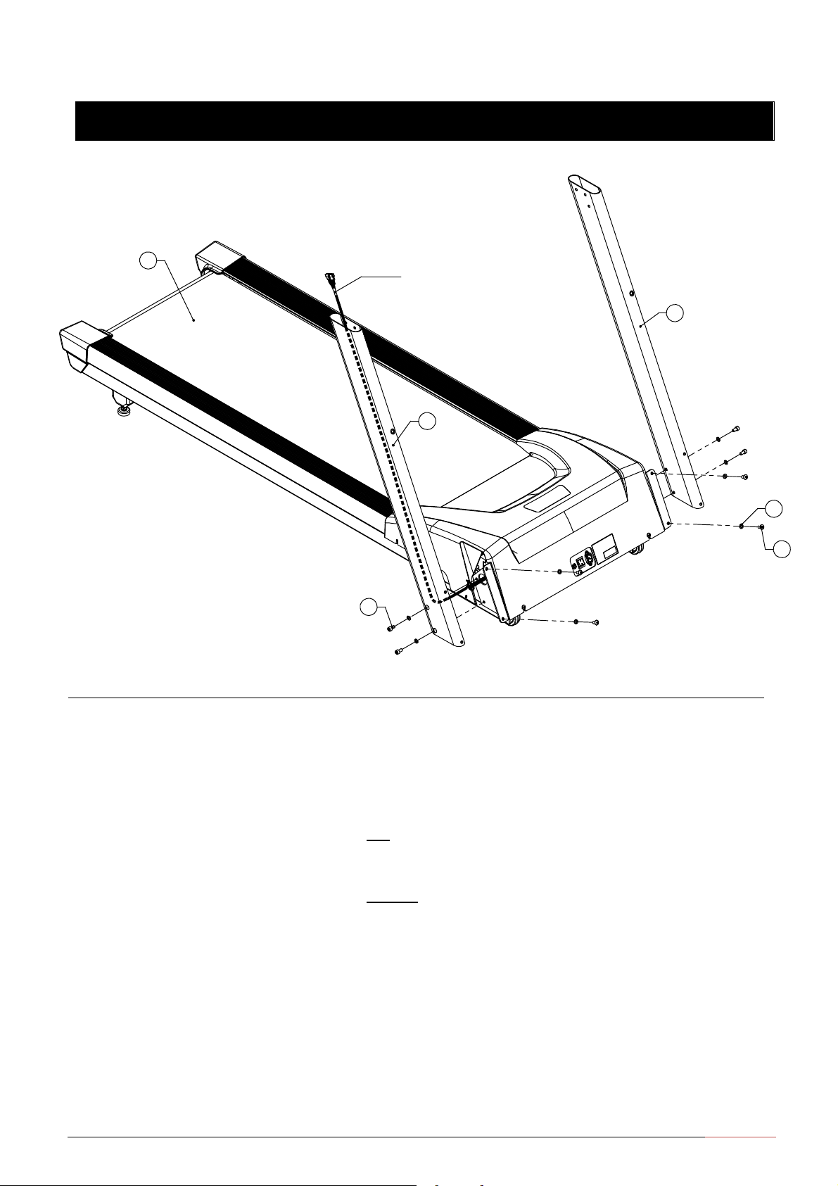
Assembly Steps
Hardware required: Assembly Step:
(a) button head screw
(b) washers
(c) socket head screw
Tool:
(N) 6mm T-handle hex
key
Qty: 4
Qty: 8
Qty: 4
#1: Unwind the wire tie from the base of the right upright
and feed it through the large hole Unwrap the cable
and tie it to the wire tie securely Draw the tie from
the base bracket
#2: Insert a button head screw (a) and a washer (b) into the
top mounting hole on the front panel, and thread the
screw so the other mounting holes line up Then insert
a button head screw (a) and a washer (b) into the
bottom mounting hole Fingers tighten
#3: Insert two socket head screws (c) and two washers (b) to
secure the upright to the base frame side bracket
Place each screw on the 6mm T-handle hex key (N) and
insert it through the cutout in the upright
#4: Attached the left upright following the steps #2 and #3,
using two button head screws (a), four washers (b), and
two socket head screws (c) Fingers tighten
/ /
0 1 $ 2 3 4 5
a
b
c
1
2
3
12
Assembly Guide and Owner’s Manual
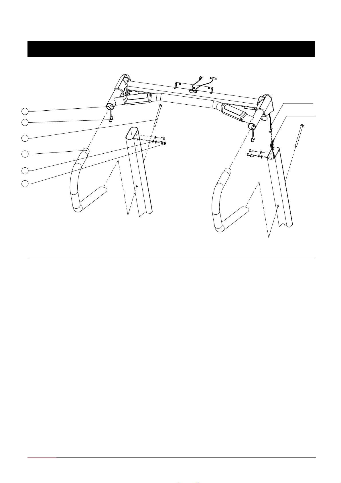
Assembly Steps
Hardware required: Assembly Step:
(a) button head screw
(b) washers
(d) button head screw
(f) button head screw
Tool:
(L) 4mm hex key
(M) 5mm hex key
(N) 6mm T-handle hex
key
Qty: 6
Qty: 6
Qty: 4
Qty: 2
#5: Connect the cables on main handrail assembly (19-0001)
and right upright (19-0029) Remove the wire tie and
place any excess cable inside the upright
#6: Lower the main handrail assembly onto the uprights
Tip the assembly slightly forward so the lip of each
handrail cap rests on the upright Align the mounting
holes and insert six button head screws (a) and six
washers (b) Fingers tighten
#7: Attached the side handrails Insert one long button
head screw (f) through the upright and the main handrail
to each side handrail
#8: Insert two button head screws (d) to secure each handrail
stub to the main handrail Wrench tighten all the
handrail screws with a 4mm hex key (L)
#9: Tighten all mounting screws from step 2 to step 7
-4 screws on front panel: use 5mm hex key (M)
-4 screws on bottom uprights: use 6mm T-handle hex
key (N)
-6 screws on upper uprights: use 5mm hex key (M)
3 4 / 5 6 7 #
3 3 4 / 5 6 7 #
4
d
f
5
b
a

Assembly Guide and Owner’s Manual 13
Assembly Steps
Hardware required: Assembly Step:
(d) button head screw
(e) washer
(a) button head screw
(b) washer
Tool:
(L) 4mm he key
(M) 5mm he key
Qty: 3
Qty: 3
Qty: 2
Qty: 2
#10: Attached the console holding bracket with three button
head screws (d) and three washers (e). Fingers tighten.
#11: Insert 2 button head screws (a) and 2 washers (b) to the
console holding bracket. Fully tighten these two
screws by 5mm he key (M).
#12: Fully tighten three button head screws (d) by 4mm he
key (L).
d
e
b
a6

14
Assembly Guide and Owner’s Manual
Assembly Steps
Hardware required: Assembly Step:
(d) button head screw
(e) washer
Tool:
(L) 4mm hex ey
Qty: 4
Qty: 4
#13: Connect the cables to their appropriate receptacles on
the bac of the console display, and feed any excess
cable into the main handrail.
#14: Align four mounting holes and secure the console
display with four button head screws (d) and four
washers (e). Tighten by a 4mm hex ey (L).
#15: Place the Safety Stop Key & Clip into the cutout on the
console display.
7
9
e
d
Back Side of Console Display Assembly
Assembly Guide and Owner’s Manual 15
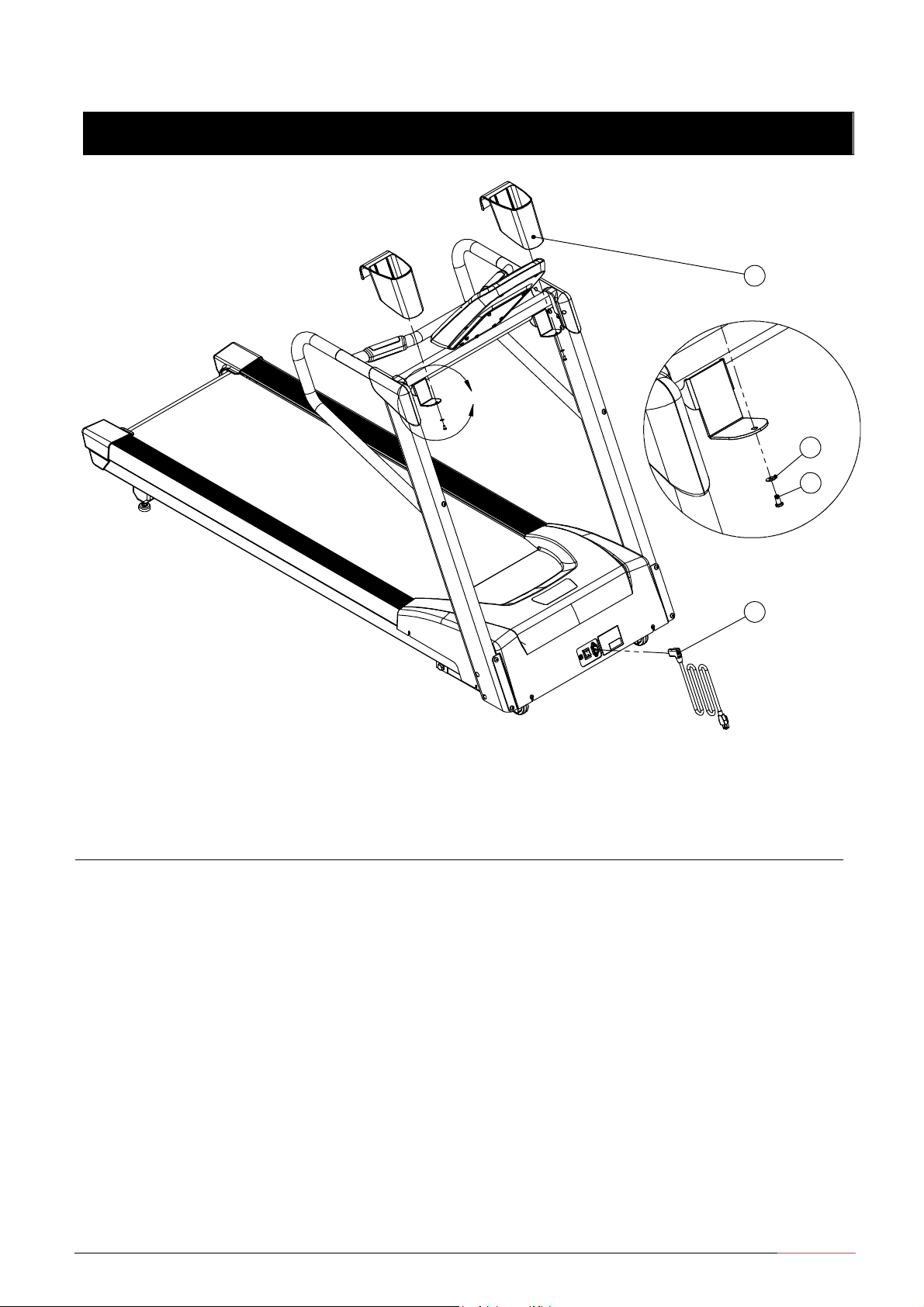
Assembly Steps
CAUTION: Before installing or changing
power cords, make sure the power is OFF and
unplug the treadmill from the power outlet
ATTENTION: Avant d'installer ou de chan er
les cordons d'alimentation, assurez-vous que
l'appareil est hors tension et débranchez le
tapis de la prise de courant.
Hardware required: Assembly Step:
(i) Phillips screw
(j) washer
Tool:
Phillips screw driver
Qty: 2
Qty: 2
#16: Slide two water bottle holders onto their brackets and
secure each with a Phillips screw (i) and washer (j)
Tighten each screw with a Phillips screw driver
#17: Install the AC power cable (
○
10
)
Note: Before using the treadmill, make sure it is level If adjustment is needed, adjust one rear
foot at a time Don’t raise the unit more than
⅟₂
inch (1 2cm) off the floor
-- Loosen the upper lock nut with a crescent wrench and rotate the rear feet as needed
-- Retighten the lock nut and lower the treadmill to the floor
Note: Check the alignment and adjust the running belt, please refer to the “General
Maintenance/Belt Adjustment”
j
i
8
10
detail A
16
Assembly Guide and Owner’s Manual
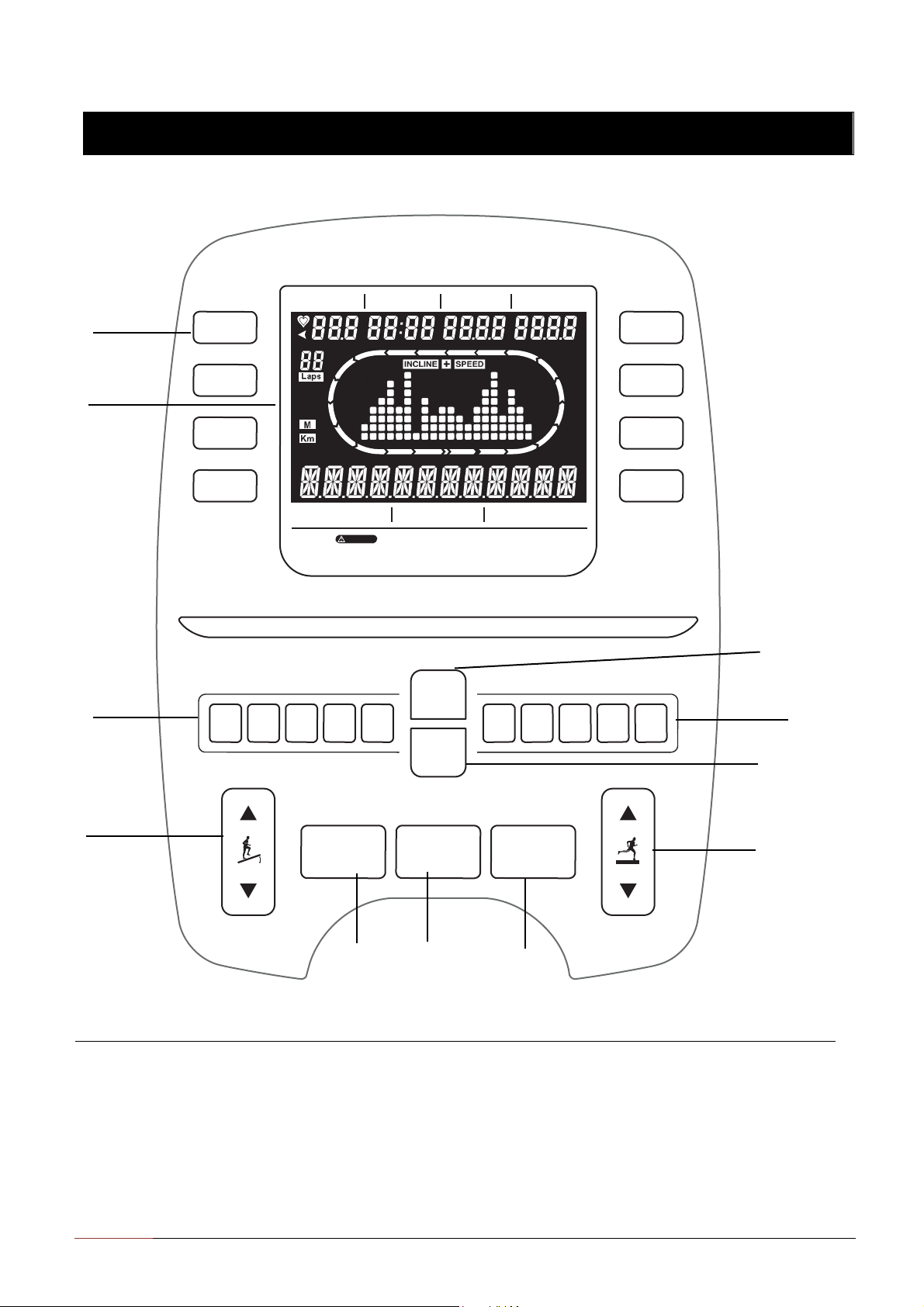
Console Display Information
○
1
Build-In Programs
○
5
PROGRAM Key
○
9
START Key
○
2
LCD display
○
6
DISPLAY Key
○
10
Speed +/-
Key
○
3
Incline Quick Keys
○
7
STOP Key
○
11
Speed Quick Keys
○
4
INCLINE +/-
Key
○
8
ENTER
Key
PULSE
TIME CALORIES
DISTANCE
P0
MANUAL
P1
WALKER
P2
FATBURN
P3
WEIGHT LOSS
P4
POWER WALKER
P5
HILL INTERVAL
H1~H2
TARGET H.R.C.
U1~U2
USER
INCLINE PROGRAM
SPEED
CAUTION:
Properly warm up and stretch before exercsing. If you feel unusual pain or dizziness
or
shortness of breath. STOP immediately and CONSULT A
PHYSICIAN.
Risk of Injury to Persons – To Avoid Injury, use extreme caution when stepping onto
or
off of a moving belt. Read Instruction Manual Before
Using.
INCLINE
SPEED
PROGRAM
10 8 6 4 2 2 4 6 8
10
DISPLAY
STOP
ENTER
START
○
1
○
2
○
3
○
4
○
7
○
8
○
9
○
11
○
10
○
5
○
6
Assembly Guide and Owner’s Manual 17
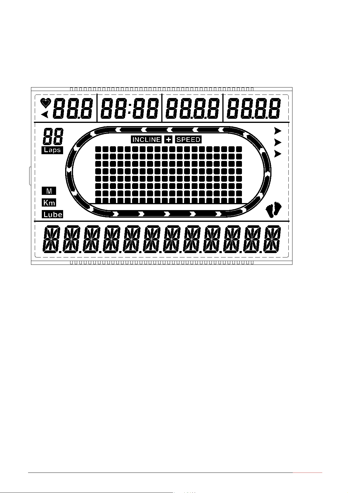
LCD display
○
A WORKOUT statistics: displayed your heart rate, workout time, calories burned, and distance
tra elled.
○
B Display Banner: It changes to the program profile when you select a program or press START.
A blinking column in the profile indicates your position.
○
C Message window: The three columns show the information about your session while you are
exercising, and show a erage PACE per minute per mile.
○
D Target Heart Rate Achieved: When you achie ed your target heart rate, this zone will be lit
up.
○
E Km/MPH: the unit is preset at MPH for speed, and when you exercise, the MPH zone will be
lit up. You can change the unit to metric, and the Km zone will be lit up.
○
F UPDATE: the zone will be lit up while the exercise data is changed.

18
Assembly Guide and Owner’s Manual
Key Pad
PROGRAM Keys: Press the key and the available programs will be displayed cycles. he program
profile appears in the center display and the abbreviated name of the program lights along the base
of the display. With the desired program displayed press the S AR key to select the program.
DISPLAY Keys: Press DISPLAY Key to switch the Incline profile to either Speed profile or SCAN mold
on the LCD display banner. On the SCAN mold, the incline profile and speed profile display by turns
every 5 seconds.
ENTER Keys: Use this key to confirm responses to specific prompts.
START Key: Press S AR key to start your workout immediately using the Manual Program.
STOP Key: A firm tap on the red S OP key slows the running belt to a stop and the treadmill enters
pause mode. o resume, press S AR or the SPEED UP arrow key. o reset to the banner, hold the
red S OP key for a few seconds or press it two more times.
INCLINE +/- Key: Press and hold the INCLINE arrow keys to increase or decrease the incline from
0% to 15% in 0.5% increments.
INCLINE Quick Keys: During most programs, when allowed, the incline may be changed using the
Incline Quick Keys. o change incline, press the digit (2, 4, 6, 8, or 10) of the Incline Quick Keys,
then the selected value will be shown in the Incline Display window and the elevation will be
changed.
SPEED +/- Key: Press and hold the SPEED arrow keys to increase or decrease the running belt
speed in 0.1 increments from 0.5mph to 12mph (or 0.5kph to 20kph).
SPEED Quick Keys: During most programs, when allowed, the speed may be changed using the
Speed Quick Keys. o change speed, press the digit (2, 4, 6, 8, or 10) of the Speed Quick Keys, then
the selected value will be shown in the SPEED Display window and the speed will be changed.

Assembly Guide and Owner’s Manual 19
Build-In Programs:
Programs code Programs
P0 MANUAL
P1 WALKER
P2 FATBURN
P3 WEIGHT LOSS
P4 POWER WORKER
P5 HILL INTERVAL
U1 USER1
U2 USER2
H1 FATBURN HR
H2 CARDIO HR
Program Profile and Default Value Summary:
P0 MANUAL Default Value Adjustable Period
Time
0 (unlimited)
10 ~ 99 min. or 0 as unlimited
Weight
155lbs (or 70kg)
40 ~ 350lbs (or 30kg ~ 160kg)
peed starts at 1.0MPH (or 1KPH) 0.5 ~ 12 MPH (0.5~ 20KPH)
Incline starts at 0% 0% ~ 15%
P1 WALKER Default Value Adjustable Period
Time 20 min. 10 ~ 99 min. or 0 as unlimited
Weight
155lbs (or 70kg)
40 ~ 350lbs (or 30kg ~ 160kg)
peed starts at 1.0MPH (or 1.0KPH) 0.5 ~ 12 MPH (0.5~ 20KPH)
Incline starts at 1% 0% ~ 15%
Warm Up
Cool Down
3 min. / 1.0MPH (or 1.0KPH) / 0% elevation
3 min. / last speed* 40%, 30%, 20% / 0% elevation
Table of contents


