Northland designer series User manual

NORTHLAND designer and
master series
INSTALLATION
INSTRUCTIONS

2
TOOL LIST
Phillips screwdriver Pliers
Flat blade screwdriver Adjustable wrench
1/4" hexhead nutdriver 1/4" open end wrench
Level Utility knife
Drill and Drill Bit (#6 - .204) Tape measure
UNPACKING:
Check Cabinet and Power Module for freight damage.
This cabinet was carefully packed and thoroughly inspected before leaving our plant.
Responsibility for its safe delivery was assumed by the carrier upon acceptance of the shipment.
Claims for loss or damage sustained in transit must be made on the carrier as follows:
Exterior damage:
Make thorough damage notation on your delivery receipt and have driver
acknowledge by signature and date. Send a written request for an inspection
report from carrier. Include the name of carrier representative and the date the inspection
was requested. Retain inspection report and receipt for filing of the claim.
Concealed damage:
This must be reported to the carrier within fifteen days. Obtain inspection
report from the carrier. Retain the inspection report for filing of the claim.
DO NOT RETURN DAMAGED MERCHANDISE TO MANUFACTURER- FILE THE
CLAIM WITH THE CARRIER.
Protect kitchen floor. Remove all packing materials from cabinet and if there was no freight damage destroy
cartoning, plastic bags and any exterior wrapping material immediately after the refrigerator is unpacked. Children
should never use these items for play. Remove all staples from the carton. Staples can cause severe cuts and
destroy finishes if they come in contact with other appliances or furniture. Carefully read and follow the child safety
precautions in the pamphlet enclosed with your new refrigerator. It is published by the Association of Home
Appliance Manufacturers.
Leveling Legs are mounted on the bottom of the cabinet. Adjust Leveling Legs to approximate desired height. Do
NOT extend Legs more than 41/4" out from BOTTOM OF CABINET or they will not be secure.
NOTE: Front legs have choice of two locations. This enables installer to recess kick area to more closely
approximate kick depth of various style cabinetry. It is important, therefore, to exercise caution to avoid “tipping”
the product and to secure product carefully.
Before you begin - Read these instructions completely and carefully
IMPORTANT - Save these instructions for local inspector's use.
IMPORTANT - OBSERVE ALL GOVERNING CODES AND ORDINANCES.
Note to Installer - Be sure to leave these instructions with the Consumer.
Note to Consumer - Keep these instructions with your Use and Care Book for future reference.
CONTENTS:
TOOL LIST & UNPACKING INSTRUCTIONS................................................................................ 2
PREINSTALLATION INSTRUCTIONS........................................................................................ 3,4
INSTALLATION INSTRUCTIONS .................................................................................................. 5
INSTALLING TWO UNITS SIDE BY SIDE ..................................................................................... 6
KICK PLATE INSTALLATION ........................................................................................................ 6
MODULE INSTALLATION........................................................................................................... 7,8
ICE MAKER WATER VALVE INSTALLATION............................................................................... 9
LOUVERED GRILLE ASSEMBLY................................................................................................ 10
HINGE AND GASKET ADJUSTMENT ......................................................................................... 11
CUSTOM DOOR PANELS ........................................................................................................... 12
"TRIMLESS" DOOR / GRILLE PANELS ...................................................................................... 13
CUSTOM GRILLE PANELS ......................................................................................................... 14
REMOVING PROTECTIVE FILM FROM PANELS ...................................................................... 14
SIDE PANEL INSTALLATIONS.................................................................................................... 15
INSTALLATION CHECKS / ERRORS.......................................................................................... 16
3
Model A
For series
starting with
(D), (G),
or (W)
()18R 17
1
⁄
2
()18FI 17
1
⁄
2
()18TI 17
1
⁄
2
()18MTI 17
1
⁄
2
()24R 23
1
⁄
2
()24FI 23
1
⁄
2
()24TI 23
1
⁄
2
()24MTI 23
1
⁄
2
()30R 29
1
⁄
2
()30FI 29
1
⁄
2
()30TI 29
1
⁄
2
()30MTI 29
1
⁄
2
()36R 35
1
⁄
2
()36FI 35
1
⁄
2
()36TI 35
1
⁄
2
()36MTI 35
1
⁄
2
()36SI 35
1
⁄
2
()36XI 35
1
⁄
2
()36MXI 35
1
⁄
2
()42SI 41
1
⁄
2
()42XI 41
1
⁄
2
()48SI 47
1
⁄
2
()48XI 47
1
⁄
2
()72RF 71
1
⁄
2
✛
Floor under Product MUST be at or above the same level as the surrounding FINISHED floor, for ease of installation
and removal.
ELECTRICAL: Provide 115 Volt, 60 Cycle, Single Phase, 15 Amp, AC Receptacle. It is recommended that a separate circuit, serving
only this appliance, be provided. Two (2) units side by side, require separate circuits, except ( ) 72RF.
PLUMBING: Ice Maker water supply line (1⁄4" O.D. Copper Tubing) to come up the rear of rough-in opening approximately 78" off
the floor depending on height adjustment. Tubing should then pass around right side of module (left for Right-Hand-
Freezer Side x Side units) and around the front to the solenoid valve (see Installation Instructions provided with the
unit).
* For special Right-Hand-Freezer Side x Side Models, place electrical receptacle in rear wall at least 781/2" high and
at least 20" from (right side) of rough-in.
IMPORTANT
For installation under a cabinet or soffit, a 3"
space should be provided above the Power
Module (as shown on left). Use a removable
panel so that the Module can be installed or
removed easily without disturbing the lower
cabinet.
Note: Rough-in height (85" to 871⁄2").
**NOTE
If no overhead cabinet or soffit is present,
you must cover the top of the rough opening
with at least 1⁄2" plywood.
Rough-In Width
82
85
1/2
24
AA
85
87
1
⁄
2
ROUGH-IN DETAIL FOR (1) UNIT
ROUGH-IN WIDTH = “A” ROUGH-IN DETAIL FOR (2) UNITS
PLACED SIDE BY SIDE
ROUGH-IN WIDTH = “A” + “A” + 1⁄2"
PRE-INSTALLATION INSTRUCTIONS
20
min. (typ)
* see note
below
Ice Maker
Tubing
78
1
/
2
min.
(typ)
22
A
22
24
78"
approx.
Receptacle must be placed in
this location for 18" Models
85
87
1
/
2
*
*
85
to
87
1
⁄
2
OVERHEAD CABINET
OR SOFFIT
1/2 PLYWOOD
3/4 x 3 REMOVABLE
PANEL
3 Min.
GRILLE
POWER MODULE
4
POWER MODULE
GRILLE
ALTERNATE POSITION
IF DEEPER TOE-SPACE
IS REQUIRED.
IMPORTANT: When installing
water line for the Ice Maker, be
suretoinstallaSHUT-OFFVALVE
at a convenient location between
theRefrigeratorandthesupplyline.
Recommended water pressure is
20 to 120 P.S.I.
Also required is an in-line WATER
FILTER between the Refrigerator
and the supply line to prevent
sediment from blocking water flow
through the Water Solenoid Valve.
NOTE
Self-piercing water valves and
plastic tubing are not approved
for water supply to Ice Maker.
Enclosure must permit Refrigerator to be
removed for Service.
For corner installations, a minimum 1" filler must be used
as shown above. For units with face-mounted handles - filler
must be 3".
1" Min.
Filler
Cabinet Outline
A
LEVELING LEGS –
4" MAX. EXTENSION FROM CABINET
(MAX. ADJUSTMENT 3")
TO TOP
EDGE OF
GRILLE
NOTE:
UNIT MUST BE INSTALLED LEVEL
IN ALL PLANES, ON A FLOOR
THAT IS STRONG ENOUGH TO
SUPPORT A FULLY LOADED
REFRIGERATOR.
REFRIGERATOR HEIGHT – ADJUSTABLE 821⁄2" TO 85"
821⁄2" Height leaves 2" from floor to bottom of door
85" Height leaves 41⁄2" from floor to bottom of door
ROUGH-IN DEPTH = 24"
82
1
⁄
2
"
TO
85"
85"
TO
87
1
⁄
2
"
Locate the refrigerator in the coolest part of the
room,outofdirectsunlightandawayfromheating
ducts or registers.
Do not place the refrigerator next to heat-
producing appliances such as a range, oven or
dishwasher. If this is not possible, a section of
cabinetryoranaddedlayerofinsulationbetween
the two appliances will help the refrigerator
operate more efficiently.

5
– READ THIS BEFORE PROCEEDING WITH INSTALLATION –
The Module comes with a 3-prong power supply cord. It must be plugged into a mating 115 volt, 60 Hz, 15 amp separately
fused, 3-prong grounded outlet serving only this product, and wired in accordance with National and Local Electrical
Codes and ordinances. A time delay fuse or circuit breaker is recommended. DO NOT USE AN EXTENSION CORD OR
ADAPTER PLUG.
DO NOT REMOVE THE GROUND PRONG FROM THE POWER SUPPLY CORD UNDER ANY CIRCUMSTANCES!
If voltage varies by 10 percent or more, performance of your refrigerator may be affected. Operating the refrigerator with
insufficient voltage can damage the compressor. Such damage is not covered under your warranty. If you suspect your
voltage is high or low, consult your power company for testing.
Do not pinch, knot, or bend the power cord in any manner.
Never unplug the refrigerator by pulling on the power cord. Always grip the plug firmly and pull straight out from the
receptacle. To avoid electrical shock, unplug the refrigerator before cleaning and before replacing a light bulb.
NOTE: Turning the control to OFF turns off the compressor, but does not disconnect power to the light bulb or other
electrical components.
Do not overcrowd the shelves or block cold air vents. Do not install a shelf closer than 8" from the top in the refrigerator
section.Donot allow packagestooverhangsides or rearofshelvesasthis will blockaircirculation,makingthe refrigerator
less efficient.
INSTALLING THE CABINET
Before placing cabinet in opening, check level of floor and adjust
leveling legs accordingly. Locate and mark the center of two wall
studs in the back of the rough opening at the height of the cabi-
net mounting bracket. The depth of the rough opening should be
at least 24". If the rough opening depth is more than 24", than a
piece of wood must be secured crosswise on the wall into studs
at the height of the cabinet mounting bracket. Move cabinet into
opening and adjust legs again if necessary to insure that the unit
is level. Check fit of toe plate and grill.
IMPORTANT: To prevent the cabinet from
tipping forward, install two screws thru the
cabinet mounting bracket into each of the
two studs located in the wall behind the cabinet.
Drill and screw through the side trim into adjourning
cabinet and/or walls.
Cabinet
Mounting
Bracket
Drill 3 holes equal distance
apart in vertical section of
aluminum frame and install
pan head screws as shown
FINISHED
WALL or
CABINETS
REFRIGERATOR
CABINET

6
Drill 3 holes each side equal distance apart
in vertical section of aluminum frame and
install screws as shown.
Wood Shim
7/8" x 1" x 68"
7/8"
1"
GF
E
D
✷Install Wood Shim to
one of the Cabinets
before installing in
rough-in cavity.
✷After properly installing
both Cabinets, drill trim
and install pan head
screws (provided).
When two units are installed together, a
231⁄2" x 12"(min.) divider panel needs to be
installed between the two modules (refer to
illustration) with self-tapping screws. The divider
panel can be made of any material available
i.e. 1⁄32" aluminum, 1⁄8"-1⁄4" wood paneling).
Locate the divider panel approximately 1" down
from top of cabinet and flush with back of
cabinet. Drill three pilot holes approximately 1⁄2"
up from bottom of divider panel, through panel,
and into cabinet. Secure panel to cabinet with
three screws using pilot holes previously drilled.
INSTALLING TWO UNITS SIDE-BY-SIDE
KICKPLATE INSTALLATION
Two clips are supplied to facilitate holding your kick plate (not supplied) in place. Simply
position and attach these clips to the rear of the kick plate so they snap on to the leveling legs,
for easier access or removal. (Notching of upper corners may be required to clear hinges).

7
IMPORTANT:
Re-check Cabinet installation for:
✷Proper space left for Grille installation.
✷Cabinet levelness.
✷Door opening and closing appearance.
✷SAFETY … To prevent unit from tipping forward:
> Are screws installed securely through front Trim into adjoining cabinetry and/or walls?
>Is Cabinet mounting bracket secured to wall studs?
After above checks have been made, proceed with refrigeration installation.
MODULE INSTALLATION
Place module on top of cabinet with the rear shoulder screws resting on the locator brackets behind the front slots.
Slidemodule towardrear ofcabinetuntil therear shoulderscrews engagetheslots inthe rearof thebrackets.Rest
the front shoulder screws into the front slots of the brackets.
IMPORTANT: Check to make sure wiring and Icemaker tubing is clear and not interfering with module seal.
If possible, do NOT start Product during construction, as dust can block Module condenser coils. If dust
accumulates on coils, vacuum immediately, using a soft brush attachment.
Do not operate the refrigerator in the presence of explosive fumes.
Do not install the refrigerator where the temperature will drop below 60°F (15°C) or rise above 110°F
(43°C). The compressor will not be able to maintain proper temperatures.
Do not overcrowd the shelves or block cold air ducts. Do not install a shelf closer than 8" from the top in
the refrigerator section. Do not allow packages to overhang sides or rear of shelves as this will block air
circulation, making the refrigerator less efficient.
REAR SHOULDER SCREW
FRONT
SHOULDER
SCREW

8
CAUTION:
Module NOT fastened to cabinet below.
Remove before tipping or transporting.
Make electrical connections
from the top of the lower cabi-
net to the junction box at left
sideofModule.IfNOIceMaker
then only one cabinet line will
be protruding. With Ice Maker,
be sure also to plug the ice
makerlineintoModule,andthe
solenoid valve as well. See
Module Diagram on right.
E
E
E
E
WATER VALVE
MODULE
JUNCTION
BOX
POWER CORD
ICE MAKER
LEADS
CABINET
LEADS
In the event you do need service, be sure to report the model number, serial number and proof of purchase to
your service representative. Model number and serial number are found on the serial nameplate, which is
located on the lower right interior wall of the cabinet. For your convenience you may want to record the following
information for your records.
Date of Purchase
Dealer's name
Dealer's Address
Dealer's city
Dealer's state Zip
Appliance serial number
Model number
E
E
E
9
ICE MAKER WATER VALVE
INSTALLATION ICE MAKER (SOLENOID)
CONNECTION
Slip solenoid valve compression nut
and compression sleeve on copper
tubing as shown in diagram. Tighten
nut onto water valve with adjustable
wrench. Turn on water supply valve.
Check fittings for leaks. Clamp Ice
makerlinefromcabinetontosolenoid
valve as shown. Tighten clamp se-
curely.
Z
Z
Z
X
X
X
X
X
X
X
X
SOLENOID
WATER
VALVE
GARDEN
HOSE
FITTING GASKET
SLEEVE
COMPRESSION
NUT
COPPER TUBING
(BY CUSTOMER)
TUBE CLAMP (2)
FILL HOSE TO
ICE MAKER
This Clamp for tube
positioning only.
Check to make sure
tube is not collapsed
or restricted after
connecting opposite
end to valve.
3
1
⁄
2
"

10
LOUVERED GRILLE ASSEMBLY
EDGE OF CABINET
GRILL TOP TRIM
SEE NOTE #2
BOTTOM OF GRILL SHOWN BEHIND TOP TRIM.
SEE NOTE #4.
CABINET TOP TRIM.
MOUNTING BRACKETS
(91180-000) #8-5/8 P.H. SCREW.
SEE NOTE #1.
INSTRUCTIONS FOR INSTALLING GRILL BRACKETS.
1. USE THE (2) TWO (91180-000) SCREWS TO SECURE EACH BRACKET TO CABINET TOP.
2. LOOSEN SCREWS AT TOP OF MOUNTING BRACKET. LEAVE .13 (2-3 SCREW THREADS) STICKING THRU THE BRACKET.
3. INSTALL GRILL BY ALIGNING SCREWS IN TOP OF THE BRACKET WITH THE SLOTS IN THE GRILL TOP TRIM.
4. GRILL IS INSTALLED WHEN BOTTOM OF GRILL FITS BEHIND THE CABINET TOP TRIM ACROSS THE FRONT.
5. PULL GRILL FORWARD-ABOUT AN INCH-AT THE TOP AND RE-TIGHTEN THE SCREWS IN THE TOP OF THE BRACKET.
34072-000
11
To expose concealed door hinge screws, first remove handle trim. Then slide trim over hinge
toward handle side. If your unit requires Door Panels, see "CUSTOM DOOR PANEL", section on
page 12.
AllhingesectionsattachedtoDOORS,adjustleftorright.TopandBottomCabinetHingesarealso
adjustable in and out.
HINGE AND GASKET
ADJUSTMENT
It is possible that doors may become out of
adjustmentinshipment.Seediagramonright.
If product is installed slightly “out of level”,
doors may not line up properly. Check this
BEFORE adjusting hinges.
NOTE: Doorgasketsoccasionallycompress
inshipment.Ifgasketdoesnotsealallaround,
warmslightlywithahairdryerandpulloutward
softly until magnet in gasket seals against
cabinet.
MASTER SERIES UNITS
To expose concealed door hinge
screws, remove plug buttons if
present.All hinge sections attached
to Doors adjust left or right. Top and
Bottom Cabinet Hinges are also
adjustable in and out. See diagram
(shown without cabinet trim).
ADJ SCREW
EDGE OF
DOOR TRIM
DOOR
CABINET
12
CUSTOM DOOR PANELS
Northland Designer Series Built-In design allows you to insert decorative material on the doors
of your refrigerator/freezer. If a panel thinner than 1⁄4" is being used, we recommend a filler be
inserted behind it for a proper fit, as frames are designed to accept up to 1⁄4" material. If a raised
panel is used, route edges to fit the frame.
CAUTION: DoorPanels mustnot exceed 50 lbs.Panelsweighingmorethan 50 lbs. maycause
product damage. We recommend that the door load (panel and food) not exceed 90 lbs.
NOTE: Do not use glass, mirrors, granite, thick wood or similar heavy materials for panels.
✷Remove Screws and Handle.
✷Slide Custom Panel into position in
door Trim opening.
✷Do ALL doors.
✷Do not replace Handle until Hinge and
Gasketadjustmentshavebeenmadeif
necessary. (See page 11.)
✷ReplaceHandleandScrewsandinstall
Plastic Screw Caps provided.
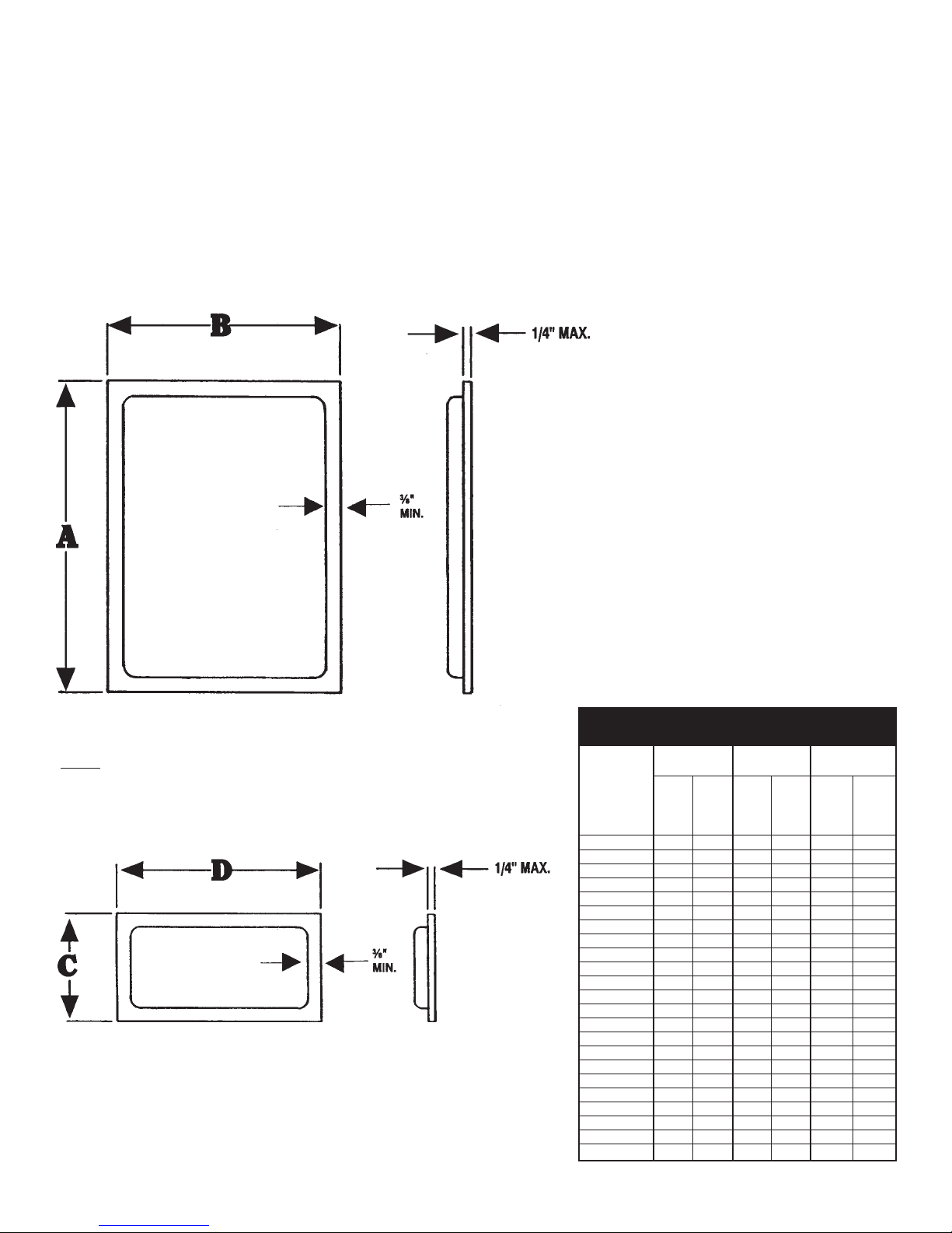
MODEL DOOR PANEL SIZES
NUMBER
Refrigerator Freezer Second freezer
door door door
For series
ABCDCD
starting with
(D), (G),
or (W)
()18R 68 15
1
⁄
2
()18FI 68 15
1
⁄
2
()18TI 45
1
⁄
8
15
1
⁄
2
22
1
⁄
4
15
1
⁄
2
()18MTI 55
1
⁄
2
15
1
⁄
2
11
7
⁄
8
15
1
⁄
2
()24R 68 21
1
⁄
2
()24FI 68 21
1
⁄
2
()24TI 45
1
⁄
8
21
1
⁄
2
22
1
⁄
4
21
1
⁄
2
()24MTI 55
1
⁄
2
21
1
⁄
2
11
7
⁄
8
21
1
⁄
2
()30R 68 27
1
⁄
2
()30FI 68 27
1
⁄
2
()30TI 45
1
⁄
8
27
1
⁄
2
22
1
⁄
4
27
1
⁄
2
()30MTI 55
1
⁄
2
27
1
⁄
2
11
7
⁄
8
27
1
⁄
2
()36R 68 33
1
⁄
2
()36FI 68 33
1
⁄
2
()36TI 45
1
⁄
8
33
1
⁄
2
22
1
⁄
4
33
1
⁄
2
()36MTI 55
1
⁄
2
33
1
⁄
2
11
7
⁄
8
33
1
⁄
2
()36SI 68 17 68 15
1
⁄
2
()36XI 68 17 22
1
⁄
4
15
1
⁄
2
45
1
⁄
8
15
1
⁄
2
()36MXI 68 17 22
1
⁄
4
15
1
⁄
2
45
1
⁄
8
15
1
⁄
2
()42SI 68 21
1
⁄
2
68 17
()42XI 68 21
1
⁄
2
22
1
⁄
4
17 45
1
⁄
8
17
()48SI 68 27
1
⁄
2
68 17
()48XI 68 27
1
⁄
2
22
1
⁄
4
17 45
1
⁄
8
17
Height
Height
Height
Width
Width
Width
Note:
All center hinged doors, cannot exceed
1/2" in panel thickness from the door
trim face.

13
3/32
“TRIMLESS” DOOR/GRILLE PANELS
Follow the same instructions for installing Custom Door Panels described on the previous
page, except prepare the Door Panels as shown to give your unit a “Trimless” appearance.
MODEL DOOR PANEL SIZES
NUMBER GRILLE
Refrigerator Freezer 2nd freezer PANEL
door door door
For series
EFEF EF E F
starting with
(D), (G),
or (W)
()18R 68
1
⁄
8
15
5
⁄
8
()18FI 68
1
⁄
8
15
5
⁄
8
()18TI 45
1
⁄
4
15
5
⁄
8
22
3
⁄
8
15
5
⁄
8
15
()18MTI 55
5
⁄
8
15
5
⁄
8
12 15
5
⁄
8
()24R 68
1
⁄
8
21
5
⁄
8
()24FI 68
1
⁄
8
21
5
⁄
8
()24TI 45
1
⁄
4
21
5
⁄
8
22
3
⁄
8
21
5
⁄
8
21
()24MTI 55
5
⁄
8
21
5
⁄
8
12 21
5
⁄
8
()30R 68
1
⁄
8
27
5
⁄
8
()30FI 68
1
⁄
8
27
5
⁄
8
()30TI 45
1
⁄
4
27
5
⁄
8
22
3
⁄
8
27
5
⁄
8
27
()30MTI 55
5
⁄
8
27
5
⁄
8
12 27
5
⁄
8
()36R 68
1
⁄
8
33
5
⁄
8
()36FI 68
1
⁄
8
33
5
⁄
8
()36TI 45
1
⁄
4
33
5
⁄
8
22
3
⁄
8
33
5
⁄
8
()36MTI 55
5
⁄
8
33
5
⁄
8
12 33
5
⁄
8
()36SI 68
1
⁄
8
17
1
⁄
8
68
1
⁄
8
15
5
⁄
8
33
()36XI 68
1
⁄
8
17
1
⁄
8
22
3
⁄
8
15
5
⁄
8
45
1
⁄
4
15
5
⁄
8
()36MXI 68
1
⁄
8
17
1
⁄
8
22
3
⁄
8
15
5
⁄
8
45
1
⁄
4
15
5
⁄
8
()42SI 68
1
⁄
8
21
5
⁄
8
68
1
⁄
8
17
1
⁄
8
()42XI 68
1
⁄
8
21
5
⁄
8
22
3
⁄
8
17
1
⁄
8
45
1
⁄
4
17
1
⁄
8
39
()48SI 68
1
⁄
8
27
5
⁄
8
68
1
⁄
8
17
1
⁄
8
()48XI 68
1
⁄
8
27
5
⁄
8
22
3
⁄
8
17
1
⁄
8
45
1
⁄
4
17
1
⁄
8
45
Height
Width
Height
Width
Height
Width
Height
Width
8
3
⁄
4
(All Models)
FRONT
OF
PANEL
E
Height
F
Width
Note:
All center hinged doors, cannot
exceed 1/2" in panel thickness
from the door trim face.
TYPICAL DOOR ASSEMBLY
WITH “TRIMLESS” PANEL
Slot - panel fits in.
1/8
MIN.
SIDE VIEW
DOOR PANEL
1/4
MAX.
Typical
All
Around
Panel
CUSTOM
DOOR
PANEL
FRONT
3/32 5/8
DOOR
14
Grille panel width
(height – 8
9
⁄
16
")
CUSTOM GRILLE PANELS
CAUTION: Grille Panels must not exceed 20 lbs.
Panels weighing more than 20 lbs. may cause product damage.
* For Grille Installation, see separate Instruction Sheets, No. 31395-000,
and No. 34072-000 for Master Series - packed in Grille package.
MODEL
NUMBER
For series
starting with
(D), (G),
or (W)
()18R 14
13
⁄
16
()18FI 14
13
⁄
16
()18TI 14
13
⁄
16
()18MTI 14
13
⁄
16
()24R 20
13
⁄
16
()24FI 20
13
⁄
16
()24TI 20
13
⁄
16
()24MTI 20
13
⁄
16
()30R 26
13
⁄
16
()30FI 26
13
⁄
16
()30TI 26
13
⁄
16
()30MTI 26
13
⁄
16
()36R 32
13
⁄
16
()36FI 32
13
⁄
16
()36TI 32
13
⁄
16
()36MTI 32
13
⁄
16
()36SI 32
13
⁄
16
()36XI 32
13
⁄
16
()36MXI 32
13
⁄
16
()42SI 38
13
⁄
16
()42XI 38
13
⁄
16
()48SI 44
13
⁄
16
()48XI 44
13
⁄
16
Note:
1/2" MIN. (RELIEF)
REMOVING PROTECTIVE FILM
FROM FACTORY INSTALLED
DECORATIVE PANELS:
✷Cabinets are shipped with protective
film over the exterior surface of
decorative panels. (optional)
✷Do not remove protective film until the
cabinet has been completely installed
to prevent scratching or marring the
decorative panels.
✷To remove the protective film, firmly
grasp the loose edge of the film and
slowly pull the film downward off the
decorative panels.
✷Decorative panels may be removed if
necessary by removing the handle
screws and handle and then sliding the
decorative panel out of the door frame.
✷Please refer to the Use and Care Guide
for cleaning.
E
E
15
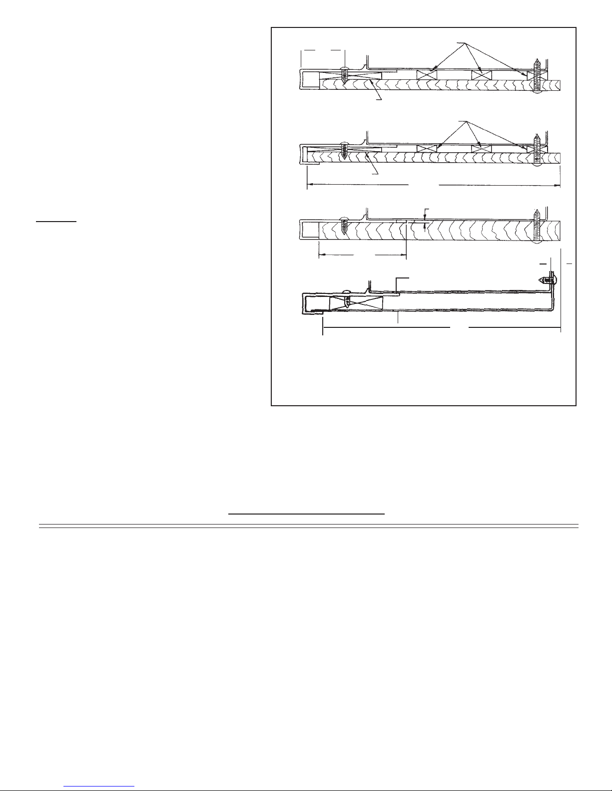
IF FASTENING SIDE PANELS TO
REFRIGERATOR:
A. Side panels should be 24"D
(or 245⁄16"D when tucked into front
trim).
B. Panel height to match installation
height.
C. Install side panels per drawings on
right.
NOTE: To avoid damage to panels or
flooring, raise panels slightly, to clear
floor when installing.
Drillthree(3)holesequaldistanceapart
in vertical section of aluminum frame
and install pan head screws as shown.
Anchorsidepanelwithscrewasshown.
Besurescrewusedgoesnomorethan
1⁄2" deep into Product. Do NOT
overtighten.
“A”
“B”
“C”
“D”
(TOP VIEW)
1
⁄
4
" THICK BATTENS
3
⁄
16
" THICK BACK UP
1
⁄
4
" PLYWOOD/PANEL
3
⁄
16
" THICK BATTENS
1
⁄
8
" THICK BACK UP
1
⁄
4
" PLYWOOD/PANEL
24
5
⁄
16
"
1
⁄
16
" ROUT
1
⁄
2
" PLYWOOD/PANEL
2
3
⁄
16
"
Drill (3) holes equal distance apart in vertical section of aluminum frame and
install #6-x
3
⁄
8
pan head screws as shown. (provided)
Attach side panel to cabinet with screws as shown. Screws must not penetrate
cabinet more than
1
⁄
2
".
TYPICAL SIDE PANEL INSTALLATIONS
✛
✛
TYP.
1
1
⁄
8
E
D
G
F
GF
11
⁄
32
"
METAL SIDE PANEL
24"
(TYP. INSTALLATION OPENING)
5
⁄
16
"
IF PRODUCT DOES NOT START WHEN PLUGGED IN, CHECK THE FOLLOWING:
1. Does light bulb go on when refrigerator door is opened? If NOT, check bulb, then …
a. Is cord from lower cabinet plugged into module?
b. Is power cord plugged in at receptacle?
c. Is circuit breaker or fuse “on”? Check by plugging another electric device into outlet.
2. If light bulb DID go on when door is opened …
a. Turn Defrost timer clockwise (might be in “Defrost”) until compressor starts.
3. If motor “hums”, but doesn’t start …
a. Check for adequate line voltage at outlet.
b. Module may have been transported or stored on side or upside down, causing
temporary displacement of motor oil. Let rest 12 to 24 hours, then plug in again.
TROUBLE SHOOTING

16
NORTHLAND KITCHEN APPLIANCE DIVISION
Northland Corporation
P.O. Box 400
Greenville, Michigan 48838-0400
34112-000
Installation Checks
•Cabinet Mounting Bracket must be installed correctly and anchored to prevent cabinet from
tipping forward.
• Rear of Module should be flush with the rear of the cabinet. Module should not stick back
beyond the rear wall of the cabinet.
•Module should be engaged in the slots on the Module positioning brackets and seated on the
foam seal without air gaps. Module positioning brackets should not be removed.
•All wires from the lower cabinet to Module must be securely connected. If a problem is
suspected, inspect both male and female plugs and insure that terminals in plug are
sufficiently forward to engage.
•Cabinet must be level both side to side and front to back. All legs should rest firmly on the
floor. Cabinetry on both sides of the cabinet must be secure and level to prevent the cabinet
from shifting when the doors are opened.
•Doors must not hit adjacent walls or counter tops.
•Gaskets must seal completely. If gaskets seal well, no further adjustments need to be made.
•On models with ice makers, check water connections for leaks. If water is not yet connected,
the plastic water fill tube to the freezer compartment must either be attached to the solenoid or
sealed to prevent air leaking into the cabinet.
•Brown and white wires should be connected to the solenoid. The remaining Molexx connector
plugs into the Power Module.
Common Installation Errors
•Any air leaks between the module and the cabinet will affect the cabinet from operating
efficiency.
•The water supply line and electric outlet must be located in a manner that will not interfere with
Module to cabinet alignment when the unit is pushed into place.
• Power cord to outlet sitting under the Power Module will create an air leak.
• Ice maker fill tube (plastic) not connected or loose creating a water and/or air leak.
•Plugs from cabinet not connected to ice maker and/or Power Module.
• Floor under products lower than finished floor making the unit inaccessible for service. Floor
under product must be strong enough to support weight of fully loaded refrigerator.
•No 3" removable panel above grill making the Power Module inaccessible for service.
• Product not anchored properly (to prevent tipping). Bracket not secured to rear wall studs or
screws through product side trim into adjoining cabinets or walls.
Table of contents
Other Northland Refrigerator manuals


