Northland 18AF-SB Manual

Installation
Operation
and
Maintenance
Instructions
Built-In
Refrigerator/Freezer
NORTHLAND BUILT-IN REFRIGERATOR/FREEZER

TABLE OF CONTENTS
Section Page
UNPACKING THE UNIT 1
PRE-INSTALLATION 2
INSTALLATION 3
CORNER INSTALLATION AND INSTALLING TWO UNITS SIDE BY SIDE 4
LEVELING THE UNIT 5
INSTALLING THE CABINET 6
INSTALLING THE MODULE 7
INSTALLING THE ICE MAKER 8
ALTITUDE ADJUSTMENT FOR TEMPERATURE CONTROL 9
INSTALLING THE GRILLE ASSEMBLY 10
HINGE AND GASKET ADJUSTMENT AND FACE MOUNTED DOOR HANDLES 11
INSTALLING THE SIDE PANELS AND KICK PLATE 12
CUSTOM DOOR PANELS AND SPECIFICATIONS 13
CUSTOM GRILLE PANELS AND SPECIFICATIONS 14
TRIMLESS DOOR PANELS AND SPECIFICATIONS 15
TRIMLESS GRILLE PANELS AND SPECIFICATIONS 16
GLASS PANEL READY WOOD FRAME DOOR SPECIFICATIONS 17
INSTALLING A DOOR FRAME TO THE GLASS DOOR 18
INSTALLATION CHECKS/COMMON ERRORS 19
TROUBLESHOOTING 20
USE AND CARE GUIDE 21
WARRANTY 24
Before you begin - Read these instructions completely and carefully.
IMPORTANT - Save these instructions for local inspector’s use.
IMPORTANT - OBSERVE ALL GOVERNING CODES AND ORDINANCES.
Note to Installer - Be sure to leave these instructions with the consumer.
Note to Consumer - Keep these instructions for future reference.

UNPACKING THE UNIT
1
Remove Packaging
Your refrigerator/freezer has been packed for shipment
with all parts that could be damaged by movement
securely fastened. Before using, be sure all packing
materials and tape have been removed.
Important
Keep your carton packaging until your refrigerator/
freezer has been thoroughly inspected and found to be
in good condition. If there is damage, the packaging
will be needed as proof of damage in transit.
Note to Customer
This merchandise was carefully packed and thoroughly
inspected before leaving our plant. Responsibility for
its safe delivery was assumed by the retailer upon ac-
ceptance of the shipment. Claims for loss or damage
sustained in transit must be made on the retailer as
follows:
Exterior and Concealed Damage•
Any damage must be reported immediately to your
retailer.
DO NOT RETURN DAMAGED MERCHANDISE TO
THE MANUFACTURER - FILE THE CLAIM WITH
THE RETAILER.
Safety
Protect your kitchen floor. Remove all packing materi-
als from cabinet and if there was no freight damage
then destroy cartoning, plastic bags and any exterior
wrapping material. Children should never use these
items for play. Remove all staples from your carton.
Staples can cause severe cuts and destroy finishes if
they come in contact with other appliances or furniture.
Carefully read and follow the child safety precautions
in the pamphlet enclosed with your new refrigerator.
It is published by the Association of Home Appliance
Manufacturers.
Tools to Have Available for Installation
Phillips Screwdriver•
Flat Blade Screwdriver•
5/16 inch & 1/4 inch Hexhead Nutdriver•
Level•
Drill and Drill Bit (#6 - .204)•
7/16 inch & 1/2 inch Open End Wrench•
Pliers•
Adjustable Wrench•
1/4 inch Open End Wrench•
Tape Measure•

PRE-INSTALLATION
2
Floor under product MUST be at or above the same level as the surrounding FINISHED floor, for ease of installa-
tion and removal.
Electrical: Provide 115 Volt, 60 Cycle, Single Phase, 15 Amp, AC Receptacle. It is recommended that a separate
circuit, serving only this appliance, be provided. *Two (2) units side-by-side require separate circuits, except the
60SS and 72SS (see Instruction Sheet 34361-000). Electrical opening should be placed 78 1/2 inches minimum
from the floor.
Plumbing: Ice maker water supply line (1/4 inch OD copper tubing) to come up the rear of cut-out opening ap-
proximately 78 inches off the floor depending on height adjustment. Tubing should then pass around the right side
of the module and around the front to the solenoid valve (see Installation Instructions provided with the unit).
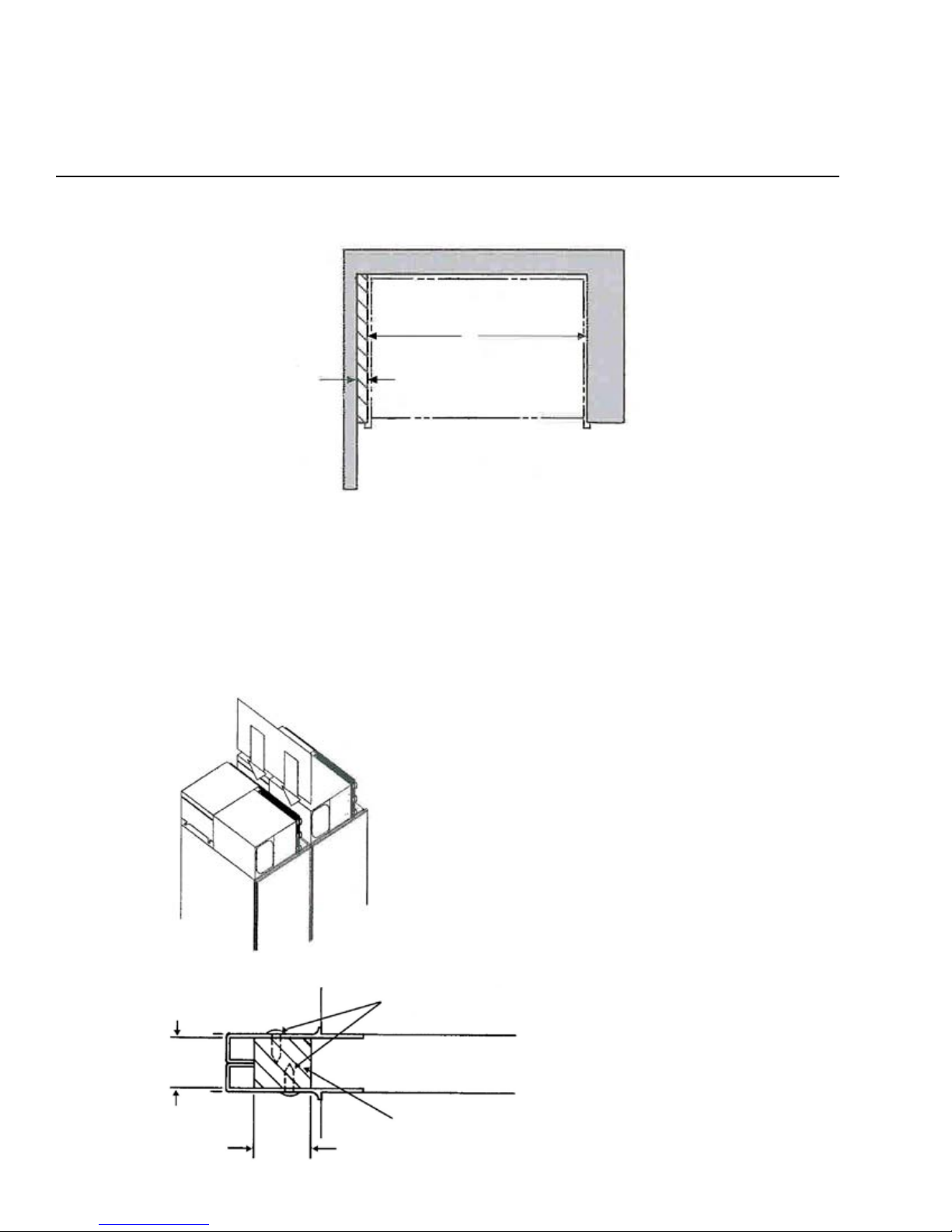
Cut-Out Detail for 1 Unit
Cut-Out Width = “A”
*Cut-Out Detail for 2 Units
Placed Side by Side
Cut-Out Width = “A” + “A” + 1/2”
Model
Cut-Out
Width
(inches)
18AR 17 1/2
18AF 17 1/2
18TF 17 1/2
18WC 17 1/2
24AR 23 1/2
24AF 23 1/2
24TF 23 1/2
24WC 23 1/2
24BC 23 1/2
242Z 23 1/2
30AR 29 1/2
30AF 29 1/2
30TF 29 1/2
36AR 35 1/2
36AF 35 1/2
36TF 35 1/2
36SS 35 1/2
363D 35 1/2
42SS 41 1/2
48SS 47 1/2
54SS 53 1/2
60SS 59 1/2
66SS 65 1/2
72SS 71 1/2
NOTE: Allow for three (3) inch high removable filler panel for easy removal of power module.
Receptacle must be placed in
this location for 18” models.
22”
22”
Ice Maker
Tubing
20”
Min. (typ)
*See note below.
A A
A
83 3/4”
to
84 1/2”
24”
24”
78”
approx.
78 1/2”
Min.
(typ) 1/2”
83 3/4”
to
84 1/2”

Electrical Connection
The module comes with a 3-prong power suppply
cord. It must be plugged into a mating 115 volt, 60
Hz, 15 amp separately fused, 3-prong grounded
outlet serving only this product, and wired in accor-
dance with National and Local Electrical Codes and
ordinances. A time delay fuse or circuit breaker is
recommended. DO NOT USE AN EXTENSION CORD
OR ADAPTER PLUG.
DO NOT REMOVE THE GROUND PRONG FROM
THE POWER SUPPLY CORD UNDER ANY CIRCUM-
STANCES!
If voltage varies by 10 percent or more, performance
of your refrigerator/freezer may be affected. Operat-
ing the refrigerator/freezer with insufficient voltage can
damage the compressor. Such damage is not covered
under your warranty. If you suspect your voltage is
high or low, consult your power company for testing.
Do NOT pinch, knot, or bend the power cord in any
manner.
NEVER unplug the refrigerator/freezer by pulling on
the power cord. Always grip the plug firmly and pull
straight out from the receptacle. To avoid electrical
shock, unplug the refrigerator/freezer before cleaning
and before replacing a light bulb.
NOTE: Turning the control to “OFF” turns off the
compressor, but does not disconnect power to the light
bulb or other electrical components. The unit MUST
be unplugged or turned off at the circuit breaker.
INSTALLATION
3
Select Location
Locate the refrigerator/freezer in the coolest part of the
room, out of direct sunlight and away from heating
ducts or registers.
Do not place the refrigerator/freezer next to heat-
producing appliances such as a range, oven or dish-
washer. If this is not possible, a section of cabinetry
or an added layer of insulation between the two (2)
appliances will help the refrigerator/freezer operate
more efficiently.
IMPORTANT
When installing the water line for the ice maker, be
sure to install a SHUT-OFF VALVE at a convenient loca-
tion between the refrigerator and the supply line.
Required water pressure range is 20 to 120 psi.
Also required is an in-line WATER FILTER between the
refrigerator and the supply line to prevent sediment
from blocking water flow through the water solenoid
valve.
NOTE: Self-piercing water valves and plastic tubing
are NOT approved for water supply to ice maker.
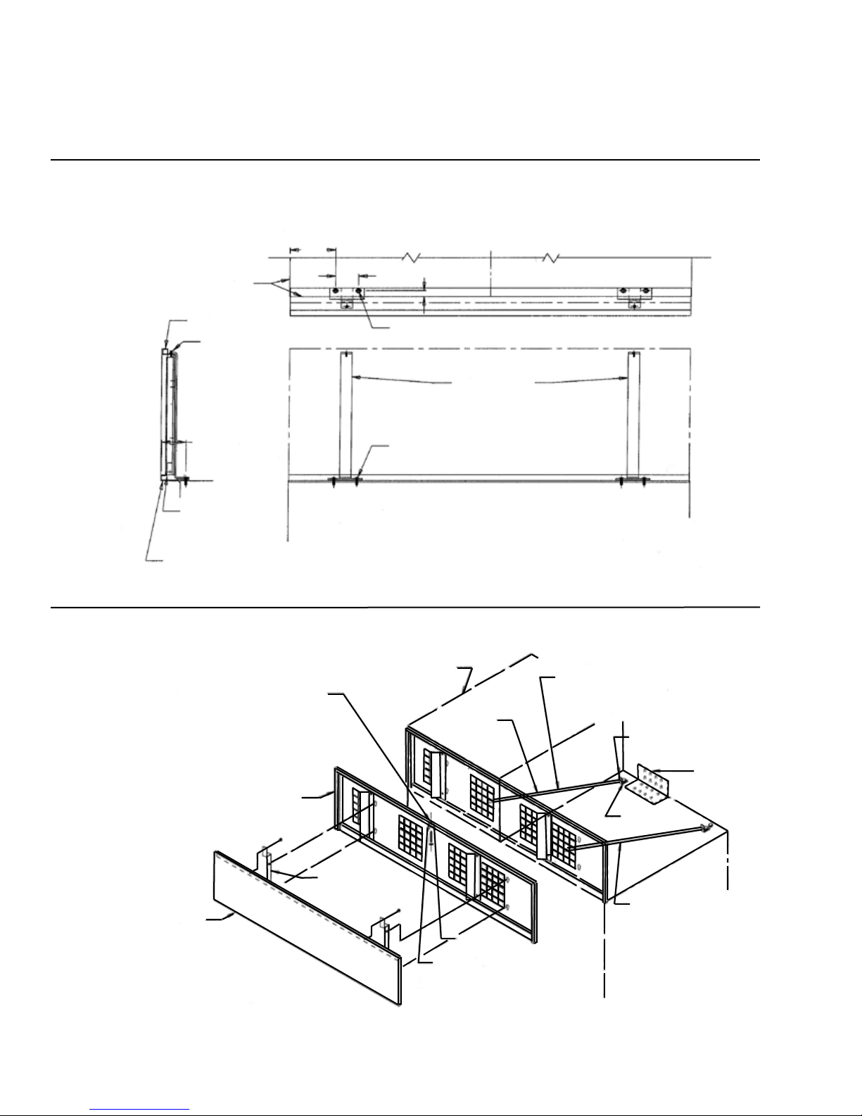
Installing Two Units Side-By-Side
When two (2) units are installed together, a 23 1/2
inch x 12 inch (minimum) divider panel needs to be
installed between the two (2) modules (refer to Illustra-
tion) with self-tapping screws. The divider panel can
be made of any material available, (i.e. 1/32 inch
aluminum, 1/8 - 1/4 inch wood paneling), or you can
order Kit # 34747-000 from the Northland Service
Department. Locate the divider panel approximately
one (1) inch down from the top of the cabinet and
flush with the back of the cabinet. Drill three (3) pilot
holes approximately 1/2 inch up from the bottom of
divider panel, through panel, and into cabinet. Secure
the panel to the cabinet with three (3) screws using
pilot holes previously drilled.
CORNER INSTALLATION AND INSTALLING TWO UNITS SIDE-BY-SIDE
4
Enclosure must permit refrigerator to be removed
for service.
PANEL READY UNITS: For corner installations, a
minimum one (1) inch filler must be used as shown
above.
ANY UNIT WITH FACE MOUNTED HANDLE: Filler
must be three (3) inches minimum.
A
Cabinet Outline
1” or
3” Min.
Filler
Install wood shim to one of the•
cabinets before installing cut-
out cavity (not provided).
After properly installing both•
cabinets, drill trim and install
pan head screws (provided).
Drill three (3) holes each side
equal distance apart in vertical
section of aluminum frame and
install screws as shown.
Wood Shim
7/8” x 1” x 68”
7/8”
1”
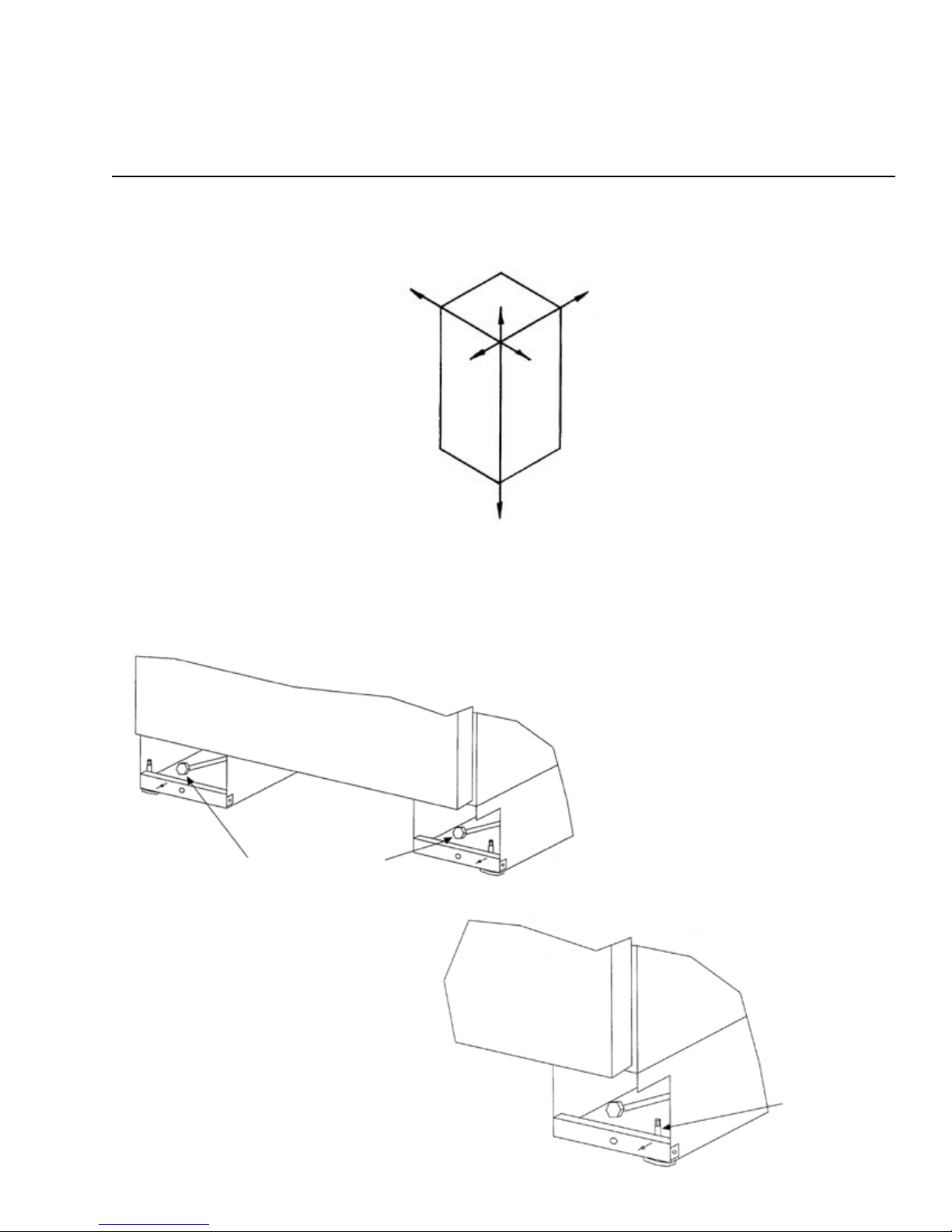
NOTE: Unit MUST be installed level in all planes, on a floor that is strong enough to support a fully loaded
refrigerator/freezer.
LEVELING THE UNIT
5
This unit is equipped with front and rear rollers. Rollers will aid during installation. Rear rollers are adjustable from
the front of the unit. Total adjustment is + 5/16, - 5/16. Turn adjusting bolt clockwise to raise cabinet and coun-
terclockwise to lower cabinet. Front leveling legs must be adjusted to the floor for leveling and to prevent the unit
from rolling during use.
Rear Roller Adjustment Bolt
Front leveling leg.
Use 1/4” wrench
to adjust height of
leveling legs.
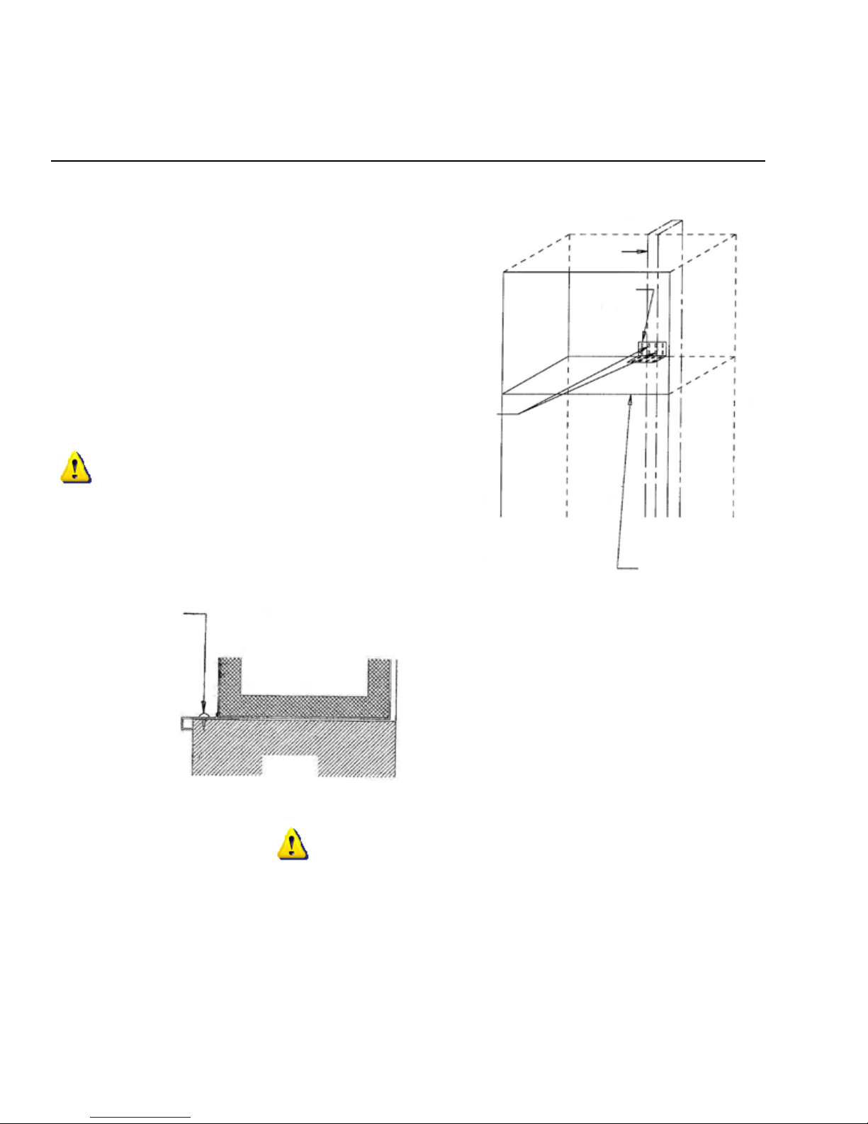
Before placing the cabinet in opening, the depth of the
cut-out opening should be at least 24 inches. If the
cut-out opening depth is more than 24 inches, then
a piece of wood must be secured crosswise on the
wall into the studs at the height of the anti-tip bracket.
Slide the cabinet into position and level the cabinet
with adjustable rear roller and front leveling legs. Lo-
cate and mark a center stud in the back of the cut-out
opening for the L-shaped anti-tip bracket- (the bracket
should fit tight to the top of the cabinet). Install at least
two screws through the bracket into the stud located
in the wall behind the cabinet. The front leveling legs
also prevent the unit from rolling during use. Check fit
of toe kick and grille.
IMPORTANT
Drill and screw through the side trim into adjoining
cabinets and/or walls for additional support.
IMPORTANT
Recheck cabinet installation for:
Proper space left for grille installation.•
Cabinet levelness.•
Door opening and closing appearance.•
SAFETY...To prevent unit from tipping forward:•
-Are screws installed securely through front trim
into adjoining cabinetry and/or walls?
-Is anti-tip mounting bracket secured to wall
studs?
After above checks have been made, proceed
with refrigeration installation.
INSTALLING THE CABINET
6
Stud
Anti-Tip
Bracket
Cabinet Top
Install at least
two (2) screws
into studs.
Do NOT install anti-tip bracket over the
top of the power module.
NOTE: 18 and 24 inch wide models have
a full anti-tip bracket across the back of
the units. The anti-tip bracket should be
attached to the wall.
Refrigerator
Cabinet
Finished
Wall or
Cabinets
Drill three (3) holes
equal distance apart
in vertical section of
aluminum frame and
install pan head screws
as shown.
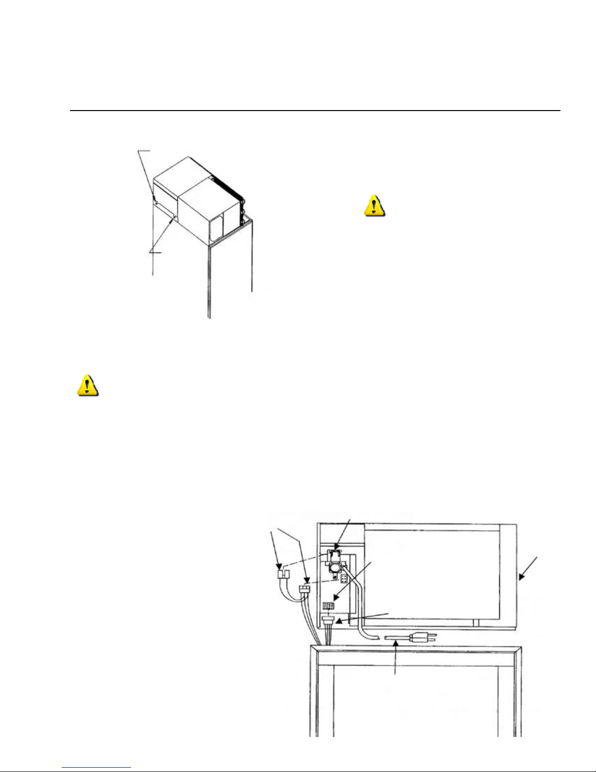
INSTALLING THE MODULE
CAUTION
Module NOT fastened to cabinet below. Remove
before tipping or transporting.
Place module on top of the cabinet with rear shoulder screws resting on the locator brackets behind the front slots.
Slide module toward the rear of the cabinet until the rear shoulder screws engage the slots in the rear of the brack-
ets. Rest the front shoulder screws into the front slots of the brackets.
IMPORTANT
Check to make sure wiring and ice maker tubing is clear and not interfering with module seal. Do NOT start prod-
uct during construction, as dust can block module condenser coils. If dust accumulates on coils, vacuum immedi-
ately, using a soft brush attachment.
Do NOT operate the refrigerator in the presence of explosive fumes.
Do NOT install the refrigerator where the temperature will drop below 60 degrees F (15 degrees C) or rise above
110 degrees F (43 degrees C). The compressor will NOT be able to maintain proper temperatures.
Make electrical connections from the top
of the lower cabinet to the junction box
at left side of module. If NO ice maker
then only one cabinet line will be pro-
tuding. With ice maker, be sure to plug
the ice maker line into the module, and
the solenoid valve as well. See module
diagram on the right.
Front
Shoulder
Screw
Rear Shoulder Screw
7
Module
Water Valve
Power Cord
Cabinet
Leads
Junction
Box
Ice Maker
Leads
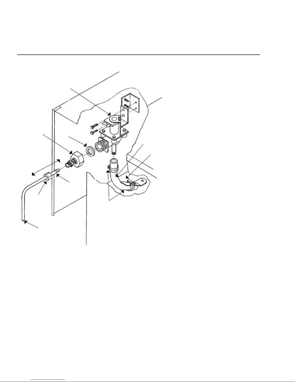
INSTALLING THE ICE MAKER WATER VALVE
Ice Maker (Solenoid) Connection
Slip solenoid valve compression nut and
compression sleeve on copper tubing
as shown in diagram. Tighten nut onto
water valve with adjustable wrench. Turn
on water supply valve. Check fittings
for leaks. Clamp ice maker line from
cabinet onto solenoid valve as shown.
Tighten clamp securely.
This clamp for tube positioning only.
Check to make sure tube is not col-
lapsed or restricted after connecting
opposite end to valve.
Fill hose to ice maker.
Tube Clamp (2)
Sleeve
Compression
Nut
Copper Tubing
(by customer)
3 1/2”
Garden Hose
Fitting Gasket
Solenoid
Water Valve
8
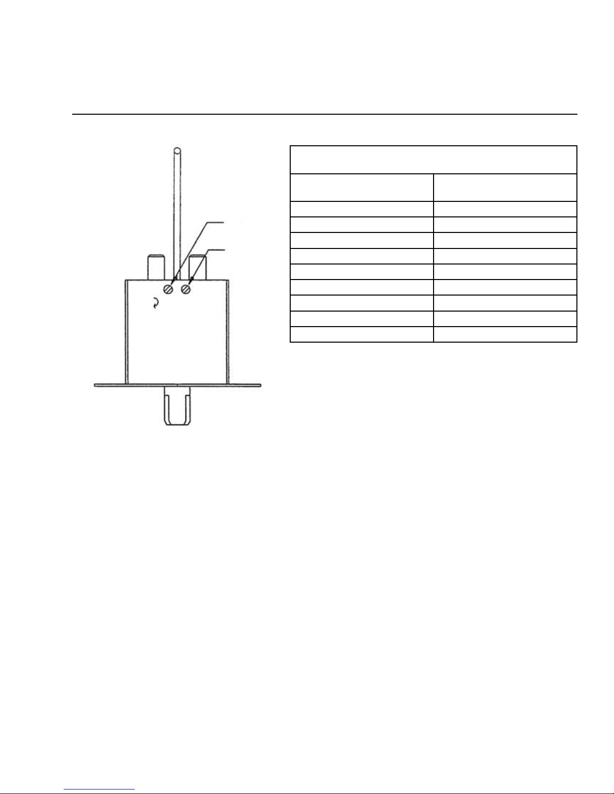
ALTITUDE ADJUSTMENT FOR FREEZER/WINE CELLAR TEMPERATURE CONTROL
ALTITUDE CORRECTION
BOTH CUT-IN & CUT-OUT SCREWS MUST BE ADJUSTED.
ALTITUDE IN FEET COUNTERCLOCKWISE
TURNS
2,000 7/60 = .12
3,000 13/60 = .22
4,000 19/60 = .32
5,000 25/60 = .42
6,000 31/60 = .52
7,000 37/60 = .62
8,000 43/60 = .72
9,000 49/60 = .82
10,000 55/60 = .92
Turn off power to refrigerator before servicing.1.
Remove screws holding freezer/wine cellar air return and drop air return grille to expose control assembly.2.
Locate cut-in and cut-out adjustment screws.3.
Determine the altitude of your location and refer to the chart above for the number of counterclockwise turns4.
to adjust the control for proper calibration. NOTE: Both cut-in and cut-out screws must be adjusted the same
amount. (NEVER exceed one full turn or damage to the control may occur.)
Reassemble the return air grille and plug in the refrigerator.5.
9
Cut-In Screw
Cut-Out Screw
In
Colder
Out
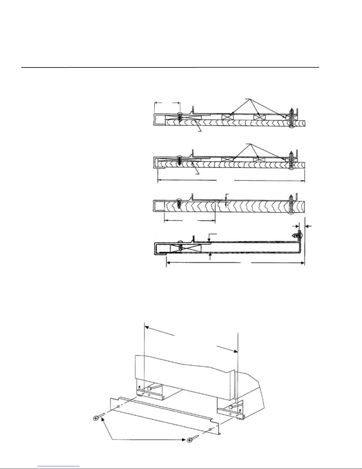
INSTALLING THE GRILLE ASSEMBLY
GRILLE MOUNTING - STYLE I BRACKET
Instructions for Installing Grille Brackets
Use the two (91180-000) screws to secure each bracket to the cabinet top.1.
Loosen the screws at the top of the mounting bracket. Leave .13 inches (2-3 screw2.
threads) sticking through the bracket.
Install the grille by aligning the screws in the top of the bracket with the slots in the3.
grille top trim.
Grille is installed when bottom of the grille fits behind the cabinet trim across the4.
front.
Pull grille forward about an inch at the top and retighten the screws in the top of the5.
bracket.
Cabinet Top Trim
Grille Top Trim
Edge of Cabinet
See Note #2.
2.06” from inside of
cabinet top trim to
centerline of holes.
Bottom of grille
shown behind top
trim. See Note #4.
Mounting Brackets
(91180-000) # 8 - 5/8 P.H. Screws
See Note #1.
Drill four (4) holes 7/64” (.109) dia.
3.81”
2.00” .45” typ. (ref.)
GRILLE MOUNTING - STYLE II SPRING
10
Instructions for Installing Grille Mounting (STYPE III) Spring
Remove screw A in mounting bracket. Mount L-bracket with screw A.1.
Hook one end of spring (81050-000) through hole in L-bracket. Holding the facia in position -2.
stretch the spring and secure the hook end to the facia through a square top hole in the facia.
GRILLE MOUNTING - STYLE II
SCREW 24”, 30” & 36” wide units will use
one (1) spring (81050-000) and
one (1) L-bracket (30483-000) to
secure the facia.
L-Bracket
(30483-000)
Anti-Tip
Bracket
Screw A
42” & 48” wide units
will use two (2) springs
(81050-000) and two (2)
L-brackets (30483-000) to
secure the facia.
Kappet Screw
(into enclosure)
Screw Cap
Module
Fasten top of grille to enclosure
with screw provided. Cover
screw head with snap-on cap.
Spring
(81050-000)
Grille Back
Facia Bracket
Facia

HINGE AND GASKET ADJUSTMENTS AND FACE MOUNTED DOOR HANDLES
11
Hinge and Gasket Adjustment
It is possible that doors may become out of adjustment
in shipment. See diagram on right.
If product is installed slightly “out of level”, doors may
not line up properly. Check this BEFORE adjusting
hinges.
NOTE: Door gaskets occasionally compress in ship-
ment. If gasket does not seal all around, warm slightly
with a hair dryer and pull outward softly until magnet
in gasket seals against cabinet.
Change or Tighten Face Mounted Door Handles
Open the door - remove the interior door shelves.1.
Remove the screws that secure the shelf mounting2.
rail and the rail.
Remove the plug buttons (exposing handle screws)3.
- make sure not to scratch the inner liner.
Remove the foam insert to expose the door handle4.
mounting screw.
Change handle/tighten screw and replace foam5.
insert, plug button, shelf rail and door shelf.
Stainless Steel Wrap Door Units
To expose concealed door hinge screws, remove plug
buttons if present. All hinge sections attached to doors
adjust left or right. Top and bottom cabinet hinges
are also adjustable in and out. See diagram (shown
without cabinet trim).
Panel Ready Doors
To expose the concealed door screws, first remove handle trim. Then slide trim over hinge toward handle side. If
your unit requires door panels, see “Custom Door Panel” section, on page 14.
All hinge sections attached to doors, adjust left or right. Top and bottom cabinet hinges are also adjustable in and
out.
Adjustable Screws
Edge of Door Trim
Door
Cabinet
Cabinet
Adjustable
Screws
Door
Foam
Shelf Mounting
Rail and Screw
Door Shelf
Plug Button
Handle Mounting
Screw
Foam Insert
Door Handle
INSTALLING THE SIDE PANELS AND KICK PLATE
12
Instructions for Fastening Side Panels to
Refrigerator
Side panels should be 24 inches D (or 241.
5/16 inches D when tucked into the front
trim).
Panel height to match installation height.2.
Install the side panels per drawings on the3.
right.
NOTE: To avoid damage to panels or floor-
ing, raise panels slightly, to clear floor when
installing.
Drill three (3) holes equal distance apart in
vertical section of aluminum frame and install
pan head screws as shown.
Anchor side panel with screw as shown. Be
sure screw used goes no more than 1/2 inch
deep into product. Do NOT overtighten.
Kick Plate Installation
Use two (2) #8 sheet metal screws to facilitate holding your kick plate in place. Mount screws in holes in roller
base. Notching of upper corners may be required to clear hinges.
Typical Side Panel Installations
Measure the distance between
mounting holes on roller base.
#8 Sheet
Metal Screw
Drill three (3) holes equal distance apart in vertical section of aluminum frame and install # 6 - 3/8 pan head
screws as shown (provided).
Attach side panel to cabinet with screws as shown. Screws must not penetrate cabinet more than 1/2 inch.
24”
“D”
“A”
“B”
“C”
Typ.
1 1/8”
1/4” Thick Battens
3/16” Thick Back Up 1/4” Plywood/Panel
3/16” Thick Battens
1/4” Plywood/Panel
1/8” Thick Back Up
24 5/16”
1/16” Rout
1/2” Plywood/Panel
2 3/16”
11/32”
5/16”
Metal Side Panel
(Typ. Installation Opening)
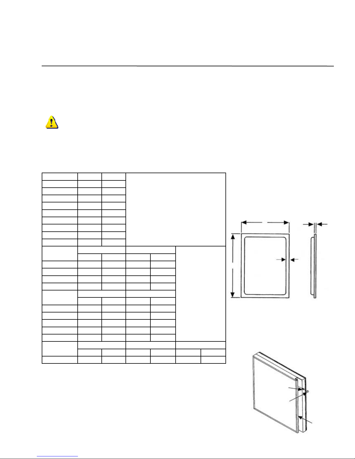
CUSTOM DOOR PANELS AND SPECIFICATIONS
The NORTHLAND Panel Ready Built-In design allows you to insert decorative material on the doors of your refrig-
erator/freezer. If a panel thinner than 1/4 inch is being used, we recommend a filler be inserted behind it for a
proper fit, as frames are designed to accept up to a 1/4 inch of material. If a raised panel is used, route edges to
fit the frame.
CAUTION
Door panels MUST NOT exceed 50 lbs. Do NOT use glass, mirrors, granite or similar heavy materials for panels.
Panels weighing more than 50 lbs. may cause product damage. We recommend that the door load (panel and
food) NOT exceed 90 lbs.
13
Model AR H W
18AR Custom Panel 68” 15 1/2”
24AR Custom Panel 68” 21 1/2”
30AR Custom Panel 68” 27 1/2”
36AR Custom Panel 68” 33 1/2”
Model AF H W
18AF Custom Panel 68” 15 1/2”
24AF Custom Panel 68” 21 1/2”
30AF Custom Panel 68” 27 1/2”
36AF Custom Panel 68” 33 1/2”
Model TF
Freezer Door Refrigerator Door
H W H W
18TF Custom Panel 22 1/4” 15 1/2” 45 1/8” 15 1/2”
24TF Custom Panel 22 1/4” 21 1/2” 45 1/8” 21 1/2”
30TF Custom Panel 22 1/4” 27 1/2” 45 1/8” 27 1/2”
36TF Custom Panel 22 1/4” 33 1/2” 45 1/8” 33 1/2”
Model SS
Freezer Door Refrigerator Door
H W H W
36SS Custom Panel 68” 15 1/2” 68” 17”
42SS Custom Panel 68” 17” 68” 21 1/2”
48SS Custom Panel 68” 17” 68” 27 1/2”
60SS Custom Panel 68” 21 1/2” 68” 33 1/2”
72SS Custom Panel 68” 33 1/2” 68” 33 1/2”
Model 3D
Freezer Door Refrigerator Door Refrigerator Door 2
H W H W H W
363D Custom Panel 22 1/4” 15 1/2” 68” 17” 45 1/8” 15 1/2”
For models:
All Refrigerator (AR), All Freezer (AF), Top Freezer (TF), Side-by-Side (SS), and Side-by-Side 3 Door (3D)
W
H
3/8”
Min.
1/4”
Max.
Removing Protective Film from Factory Installed Decorative Panels
Cabinets are shipped with protective film over the exterior surface of•
decorative panels (optional).
Do NOT remove protective film until the cabinet has been completely•
installed to prevent scratching or marring the decorative panels.
To remove the protective film, firmly grasp the loose edge of the film•
and slowly pull the film downward off the decorative panels.
Decorative panels may be removed if necessary by removing the•
handle screws and handle and then sliding the decorative panel out
of the frame.
Screw
Screw
Cap
Handle
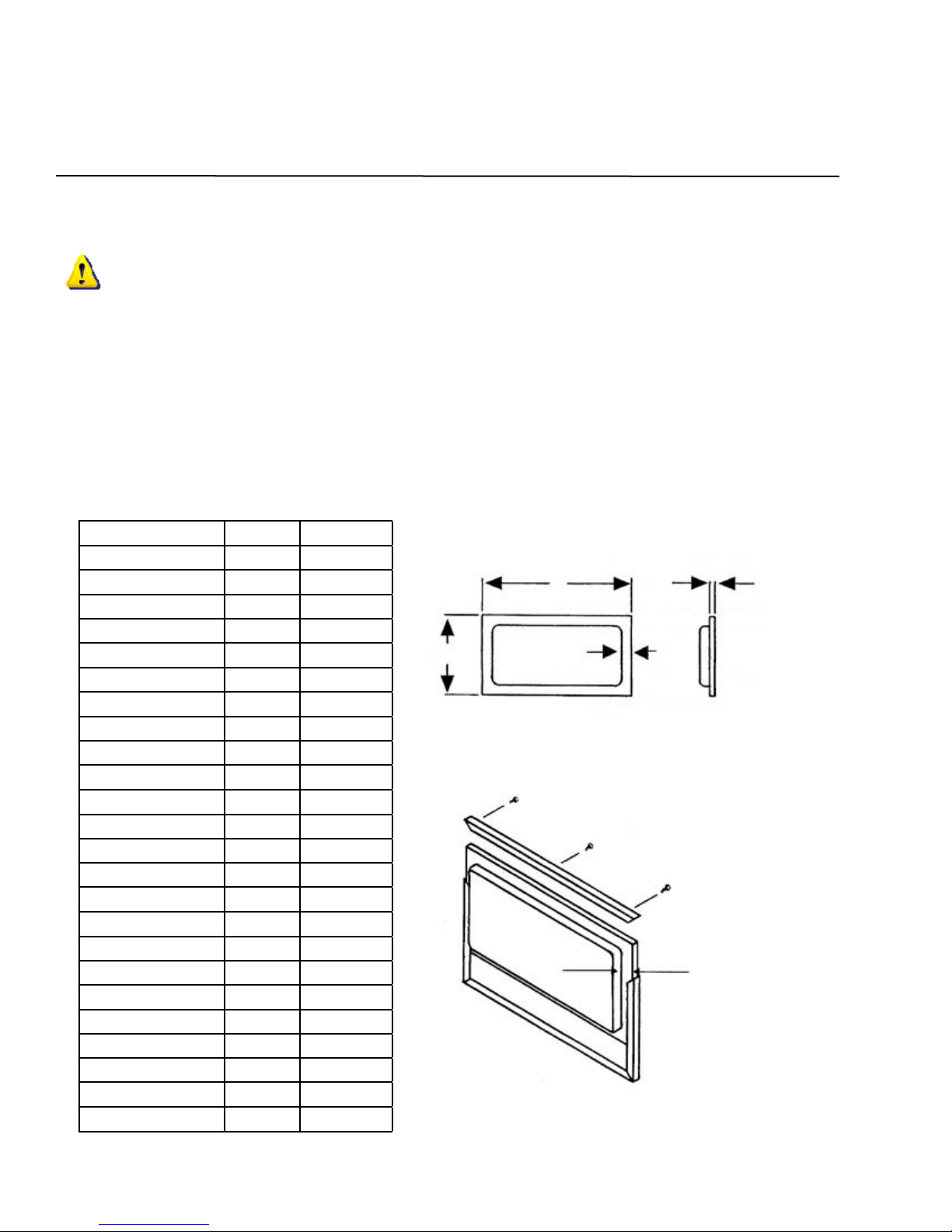
CUSTOM GRILLE PANELS AND SPECIFICATIONS
For models:
All Refrigerator (AR), All Freezer (AF), Top Freezer (TF), Side-by-Side (SS), and Side-by-Side 3 Door (3D)
Model AR H W
18AR Grille Panel 8 9/16” 14 13/16”
24AR Grille Panel 8 9/16” 20 13/16”
30AR Grille Panel 8 9/16” 26 13/16”
36AR Grille Panel 8 9/16” 32 13/16”
Model AF H W
18AF Grille Panel 8 9/16” 14 13/16”
24AF Grille Panel 8 9/16” 20 13/16”
30AF Grille Panel 8 9/16” 26 13/16”
36AF Grille Panel 8 9/16” 32 13/16”
Model TF H W
18TF Grille Panel 8 9/16” 14 13/16”
24TF Grille Panel 8 9/16” 20 13/16”
30TF Grille Panel 8 9/16” 26 13/16”
36TF Grille Panel 8 9/16” 32 13/16”
Model SS H W
36SS Grille Panel 8 9/16” 32 13/16”
42SS Grille Panel 8 9/16” 38 13/16”
48SS Grille Panel 8 9/16” 44 13/16”
54SS Grille Panel 8 9/16” 50 13/16”
60SS Grille Panel 8 9/16” 56 13/16”
66SS Grille Panel 8 9/16” 62 13/16”
72SS Grille Panel 8 9/16” 68 13/16”
Model 3D H W
363D Grille Panel 8 9/16” 32 13/16”
14
Custom Grille Panels
CAUTION
Grille panels MUST NOT exceed 20 lbs. Panels
weighing more than 20 lbs. may cause product dam-
age.
For grille installation refer to page 11, Grille Assembly
Installation, and see separate Instruction Sheet, No.
31395-000.
Remove screws and handle.•
Slide custom panel into position in door trim•
opening.
Do ALL doors.•
Do NOT replace handle until hinge and gasket•
adjustments have been made. See page 12.
Replace handle and screws and install plastic•
screw caps provided.
NOTE: All center hinged doors CANNOT exceed 1/2
inch in panel thickness from the door trim face.
Note: 1/2” Min. (Relief)
1/4” Max.
3/8”
Min.
W
H

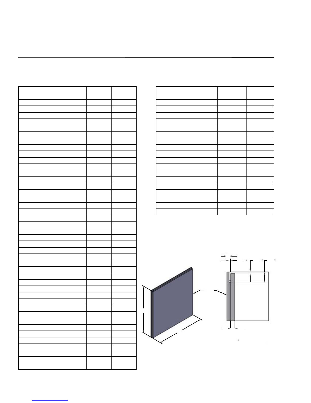
TRIMLESS OVERLAY DOOR PANELS AND SPECIFICATIONS
For models:
All Refrigerator (AR), All Freezer (AF), Top Freezer (TF), Side-by-Side (SS), and Side-by-Side 3 Door (3D)
Model 18AR & 18AF H W
Refrigerator or Freezer Overlay Panel 68 1/4” 15 3/4”
Refrigerator or Freezer Spacer Panel 66 3/4” 14 1/4”
Refrigerator or Freezer Backer Panel 68” 15 1/2”
Model 24AR & 24AF H W
Refrigerator or Freezer Overlay Panel 68 1/4” 21 3/4”
Refrigerator or Freezer Spacer Panel 66 3/4” 20 1/4”
Refrigerator or Freezer Backer Panel 68” 21 1/2”
Model 30AR & 30AF H W
Refrigerator or Freezer Overlay Panel 68 1/4” 27 3/4”
Refrigerator or Freezer Spacer Panel 66 3/4” 26 1/4”
Refrigerator or Freezer Backer Panel 68” 27 1/2”
Model 36AR & 36AF H W
Refrigerator or Freezer Overlay Panel 68 1/4” 33 3/4”
Refrigerator or Freezer Spacer Panel 66 3/4” 32 1/4”
Refrigerator or Freezer Backer Panel 68” 33 1/2”
Model 18TF H W
Refrigerator Overlay Panel 45 3/8” 15 3/4”
Refrigerator Spacer Panel 43 7/8” 14 1/4”
Refrigerator Backer Panel 45 1/8” 15 1/2”
H W
Freezer Overlay Panel 22 1/2” 15 3/4”
Freezer Spacer Panel 21” 14 1/4”
Freezer Backer Panel 22 1/4” 15 1/2”
Model 24TF H W
Refrigerator Overlay Panel 45 3/8” 21 3/4”
Refrigerator Spacer Panel 43 7/8” 20 1/4”
Refrigerator Backer Panel 45 1/8” 21 1/2”
H W
Freezer Overlay Panel 22 1/2” 21 3/4”
Freezer Spacer Panel 21” 20 1/4”
Freezer Backer Panel 22 1/4” 21 1/2”
Model 30TF H W
Refrigerator Overlay Panel 45 3/8” 27 3/4”
Refrigerator Spacer Panel 43 7/8” 26 1/4”
Refrigerator Backer Panel 45 1/8” 27 1/2”
H W
Freezer Overlay Panel 22 1/2” 27 3/4”
Freezer Spacer Panel 21” 26 1/4”
Freezer Backer Panel 22 1/4” 27 1/2”
Model 36TF H W
Refrigerator Overlay Panel 45 3/8” 33 3/4”
Refrigerator Spacer Panel 43 7/8” 32 1/4”
Refrigerator Backer Panel 45 1/8” 33 1/2”
H W
Freezer Overlay Panel 22 1/2” 33 3/4”
Freezer Spacer Panel 21” 32 1/4”
Freezer Backer Panel 22 1/4” 33 1/2”
Model 36SS H W
Refrigerator Overlay Panel 68 1/4” 17 1/4”
Refrigerator Spacer Panel 66 3/4” 15 3/4”
Refrigerator Backer Panel 68” 17”
H W
Freezer Overlay Panel 68 1/4” 15 3/4”
Freezer Spacer Panel 66 3/4” 14 1/4”
Freezer Backer Panel 68” 15 1/2”
Model 42SS H W
Refrigerator Overlay Panel 68 1/4” 21 3/4”
Refrigerator Spacer Panel 66 3/4” 20 1/4”
Refrigerator Backer Panel 68” 21 1/2”
H W
Freezer Overlay Panel 68 1/4” 17 1/4”
Freezer Spacer Panel 66 3/4” 15 3/4”
Freezer Backer Panel 68” 17”
Model 48SS H W
Refrigerator Overlay Panel 68 1/4” 27 3/4”
Refrigerator Spacer Panel 66 3/4” 26 1/4”
Refrigerator Backer Panel 68” 27 1/2”
H W
Freezer Overlay Panel 68 1/4” 17 1/4”
Freezer Spacer Panel 66 3/4” 15 3/4”
Freezer Backer Panel 68” 17”
Model 60SS H W
Refrigerator Overlay Panel 68 1/4” 33 3/4”
Refrigerator Spacer Panel 66 3/4” 32 1/4”
Refrigerator Backer Panel 68” 33 1/2”
H W
Freezer Overlay Panel 68 1/4” 21 3/4”
Freezer Spacer Panel 66 3/4” 20 1/4”
Freezer Backer Panel 68” 21 1/2”
Model 72SS H W
Refrigerator Overlay Panel 68 1/4” 33 3/4”
Refrigerator Spacer Panel 66 3/4” 32 1/4”
Refrigerator Backer Panel 68” 33 1/2”
H W
Freezer Overlay Panel 68 1/4” 33 3/4”
Freezer Spacer Panel 66 3/4” 32 1/4”
Freezer Backer Panel 68” 33 1/2”
Model 363D H W
Refrigerator 1 Overlay Panel 68 1/4” 17 1/4”
Refrigerator 1 Spacer Panel 66 3/4” 15 3/4”
Refrigerator 1 Backer Panel 68” 17”
H W
Refrigerator 2 Overlay Panel 45 3/8” 15 3/4”
Refrigerator 2 Spacer Panel 43 7/8” 14 1/4”
Refrigerator 2 Backer Panel 45 1/8” 15 1/2”
H W
Freezer Overlay Panel 22 1/2” 15 3/4”
Freezer Spacer Panel 21” 14 1/4”
Freezer Backer Panel 22 1/4” 15 1/2”
15
Typical Door Assembly with “Trimless” Panel
Slot - panel fits in.
3/32” 3/32” 5/8”
Custom
Door
Panel
Front
Door
1/8”
Min.
1/4”
Max.
Typical
All
Around
Panel
TRIMLESS OVERLAY GRILLE PANELS AND SPECIFICATIONS
Model 18AR & 18AF H W
Refrigerator or Freezer Grille Overlay Panel 8 7/8” 15 1/8”
Refrigerator or Freezer Grille Spacer Panel 7 5/16” 13 9/16”
Refrigerator or Freezer Grille Backer Panel 8 9/16” 14 13/16”
Model 24AR & 24AF H W
Refrigerator or Freezer Grille Overlay Panel 8 7/8” 21 1/8”
Refrigerator or Freezer Grille Spacer Panel 7 5/16” 19 9/16”
Refrigerator or Freezer Grille Backer Panel 8 9/16” 20 13/16”
Model 30AR & 30AF H W
Refrigerator or Freezer Grille Overlay Panel 8 7/8” 27 1/8”
Refrigerator or Freezer Grille Spacer Panel 7 5/16” 25 9/16”
Refrigerator or Freezer Grille Backer Panel 8 9/16” 26 13/16”
Model 36AR & 36AF H W
Refrigerator or Freezer Grille Overlay Panel 8 7/8” 33 1/8”
Refrigerator or Freezer Grille Spacer Panel 7 5/16” 31 9/16”
Refrigerator or Freezer Grille Backer Panel 8 9/16” 32 13/16”
Model 18TF H W
Top Freezer Grille Overlay Panel 8 7/8” 15 1/8”
Top Freezer Grille Spacer Panel 7 5/16” 13 9/16”
Top Freezer Grille Backer Panel 8 9/16” 14 13/16”
Model 24TF H W
Top Freezer Grille Overlay Panel 8 7/8” 21 1/8”
Top Freezer Grille Spacer Panel 7 5/16” 19 9/16”
Top Freezer Grille Backer Panel 8 9/16” 20 13/16”
Model 30TF H W
Top Freezer Grille Overlay Panel 8 7/8” 27 1/8”
Top Freezer Grille Spacer Panel 7 5/16” 25 9/16”
Top Freezer Grille Backer Panel 8 9/16” 26 13/16”
Model 36TF H W
Top Freezer Grille Overlay Panel 8 7/8” 33 1/8”
Top Freezer Grille Spacer Panel 7 5/16” 31 9/16”
Top Freezer Grille Backer Panel 8 9/16” 32 13/16”
Model 36SS H W
Side-by-Side Grille Overlay Panel 8 7/8” 33 1/8”
Side-by-Side Grille Overlay Panel 7 5/16” 31 9/16”
Side-by-Side Grille Overlay Panel 8 9/16” 32 13/16”
Model 363D H W
Three Door Grille Overlay Panel 8 7/8” 33 1/8”
Three Door Grille Spacer Panel 7 5/16” 31 9/16”
Three Door Grille Backer Panel 8 9/16” 32 13/16”
Model 42SS H W
Side-by-Side Grille Overlay Panel 8 7/8” 39 1/8”
Side-by-Side Grille Overlay Panel 7 5/16” 37 9/16”
Side-by-Side Grille Overlay Panel 8 9/16” 38 13/16”
For models:
All Refrigerator (AR), All Freezer (AF), Top Freezer (TF), Side-by-Side (SS), and Side-by-Side 3 Door (3D)
16
Model 48SS H W
Side-by-Side Grille Overlay Panel 8 7/8” 45 1/8”
Side-by-Side Grille Overlay Panel 7 5/16” 43 9/16”
Side-by-Side Grille Overlay Panel 8 9/16” 44 13/16”
Model 54SS H W
Side-by-Side Grille Overlay Panel 8 7/8” 51 1/8”
Side-by-Side Grille Overlay Panel 7 5/16” 49 9/16”
Side-by-Side Grille Overlay Panel 8 9/16” 50 13/16”
Model 60SS H W
Side-by-Side Grille Overlay Panel 8 7/8” 57 1/8”
Side-by-Side Grille Overlay Panel 7 5/16” 55 9/16”
Side-by-Side Grille Overlay Panel 8 9/16” 56 13/16”
Model 66SS H W
Side-by-Side Grille Overlay Panel 8 7/8” 63 1/8”
Side-by-Side Grille Overlay Panel 7 5/16” 61 9/16”
Side-by-Side Grille Overlay Panel 8 9/16” 62 13/16”
Model 72SS H W
Side-by-Side Grille Overlay Panel 8 7/8” 69 1/8”
Side-by-Side Grille Overlay Panel 7 5/16” 67 9/16”
Side-by-Side Grille Overlay Panel 8 9/16” 68 13/16”
Typical Grille Assembly with “Trimless” Panel
1/8”
Min.
3/32” 3/32” 5/8”
1/4”
Max.
H
W
Typical All
Around Panel
Custom
Grille
Panel
Front Grille Frame

GLASS PANEL READY WOOD FRAME DOOR SPECIFICATIONS
17
Model AR H W Frame with
Min.
18AR - WGP 68 1/8” 16 1/4” 2 1/2”
18AR - SGP 68 1/8” 16 1/4” 2 1/2”
24AR - WGP 68 1/8” 22 1/4” 2 1/2”
24AR - SGP 68 1/8” 22 1/4” 2 1/2”
30AR - WGP 68 1/8” 28 1/4” 2 1/2”
30AR - SGP 68 1/8” 28 1/4” 2 1/2”
36AR - WGP 68 1/8” 34 1/4” 2 1/2”
36AR - WGP 68 1/8” 34 1/4” 2 1/2”
Model WC H W Frame with
Min.
18WC - SGP 68 1/8” 16 1/4” 2 1/2”
24WC - SGP 68 1/8” 22 1/4” 2 1/2”
Model 2Z H W Frame with
Min.
242Z - SGP 68 1/8” 22 1/4” 2 1/2”
Model BC H W Frame with
Min.
24BC - SGP 68 1/8” 22 1/4” 2 1/2”
Model SS H W Frame with
Min.
60SS - WGP 68 1/8” 34 1/4” 2 1/2”
60SS - SGP 68 1/8” 34 1/4” 2 1/2”
72SS - WGP 68 1/8” 34 1/4” 2 1/2”
72SS - SGP 68 1/8” 34 1/4” 2 1/2”
H
W
2.50” Typ.
All Around .50”
.33” Typ.
(2) Plcs.
1.38” Typ.
(2) Plcs.
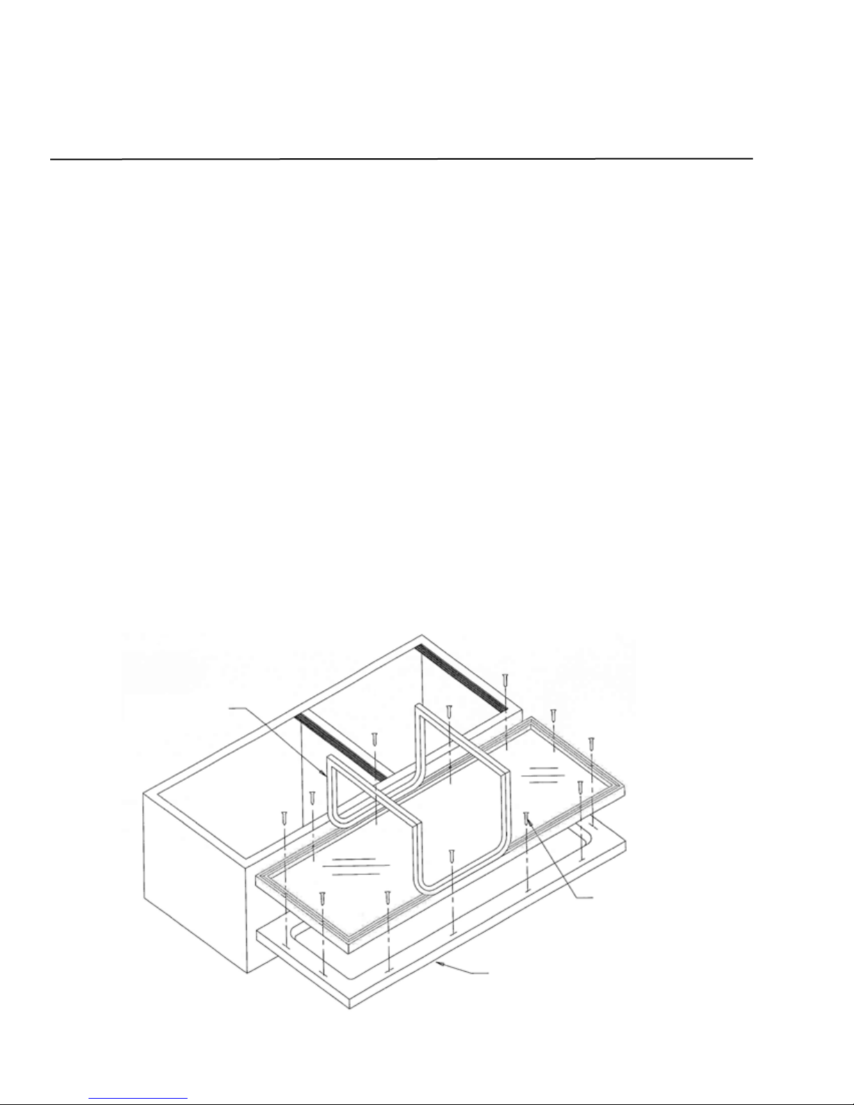
INSTALLING A DOOR FRAME TO THE GLASS DOOR
18
The door frame can be mounted to the glass door with the glass door on or off the unit. The door handle needs to
be mounted to the door frame before the frame is mounted to the glass door.
Glass Door On the Unit
Lay the unit on its back.1.
Open the glass door 180 degrees and support the glass door during installation.2.
Pull the door gasket back along the top and bottom of the glass door to expose the mounting holes for the3.
door frame. There are twelve (12) total mounting holes on the door - four (4) on each side and two (2) on the
top and bottom of the door. Screws will be mounted around the outside diameter of the door on the gasket
side.
Line up the door frame that is to be mounted to the unit and mark the hole locations on the door frame. Drill4.
1/8” pilot holes, 1/4” deep to aid during mounting of the door frame.
Recommended screws to use to mount the door frame are 1 1/4” long wood screws.5.
After installing the mounting screws, press the door gasket back into the gasket retainer. Make sure the gasket6.
is seated into the corners to retain proper door gasket seal.
Glass Door Off the Unit
Remove the four (4) hinge bolts from the door- two (2) at the top and two (2) at the bottom of the door. Retain1.
the two (2) hinge spacers. One (1) at the top and one (1) at the bottom of the door.
Lay the glass door on a surface that will protect the door frame during assembly of the frame to the glass door.2.
Complete Steps 3 through 6 as listed in the above section “Glass Door On the Unit”.3.
Mount the door to the unit using the hinge spacers and hinge bolts that were removed when taking the glass4.
door off the unit.
Door Frame
Door Gasket
(shown pulled up)
Screws to mount the door
frame to the glass door.
This manual suits for next models
142
Table of contents
Other Northland Refrigerator manuals


Popular Refrigerator manuals by other brands

GE
GE GFSS6KEXSS - r 25.8 cu. Ft. Refrigerator Dimensions and installation information

Hotpoint
Hotpoint RLAV21P Instructions for installation and use

Gram
Gram BAKER 610 Instructions for use

LIBHOF
LIBHOF B-35H user manual

MPM
MPM MPM-30-MBS-06/L user manual

Whirlpool
Whirlpool WRS325FDAB Installation instructions and owner's manual


