1-1. Model Information --------------------------------------------------------------------------------------------------------------------------------
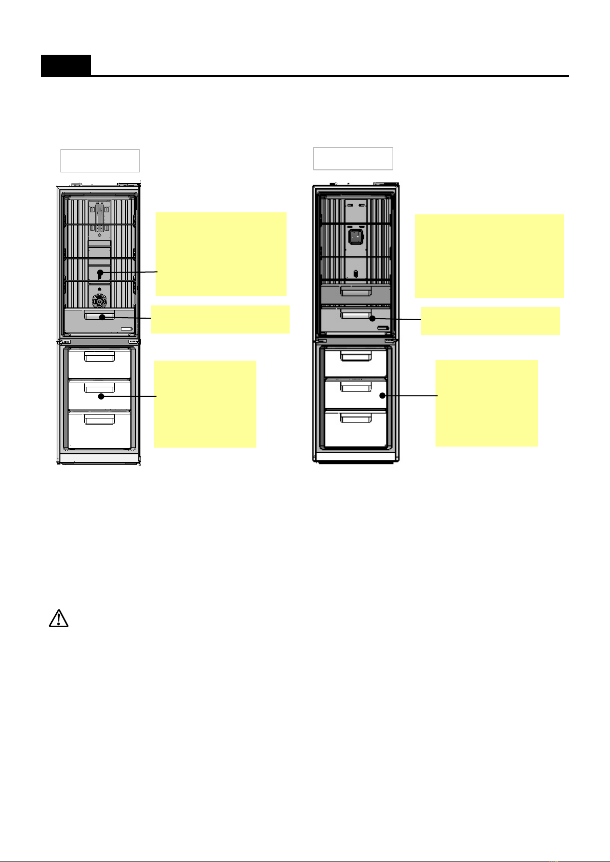
1-2. Outside Dimensions & Interior Parts -------------------------------------------------------------------------------------------------------
1-3. Machine Compartment View ------------------------------------------------------------------------------------------------------------------
1-4. Refrigerant Cycle -----------------------------------------------------------------------------------------------------------------------------------
1-5. Temperature Diagram ----------------------------------------------------------------------------------------------------------------------------
1-6. Wire Diagram -----------------------------------------------------------------------------------------------------------------------------------------
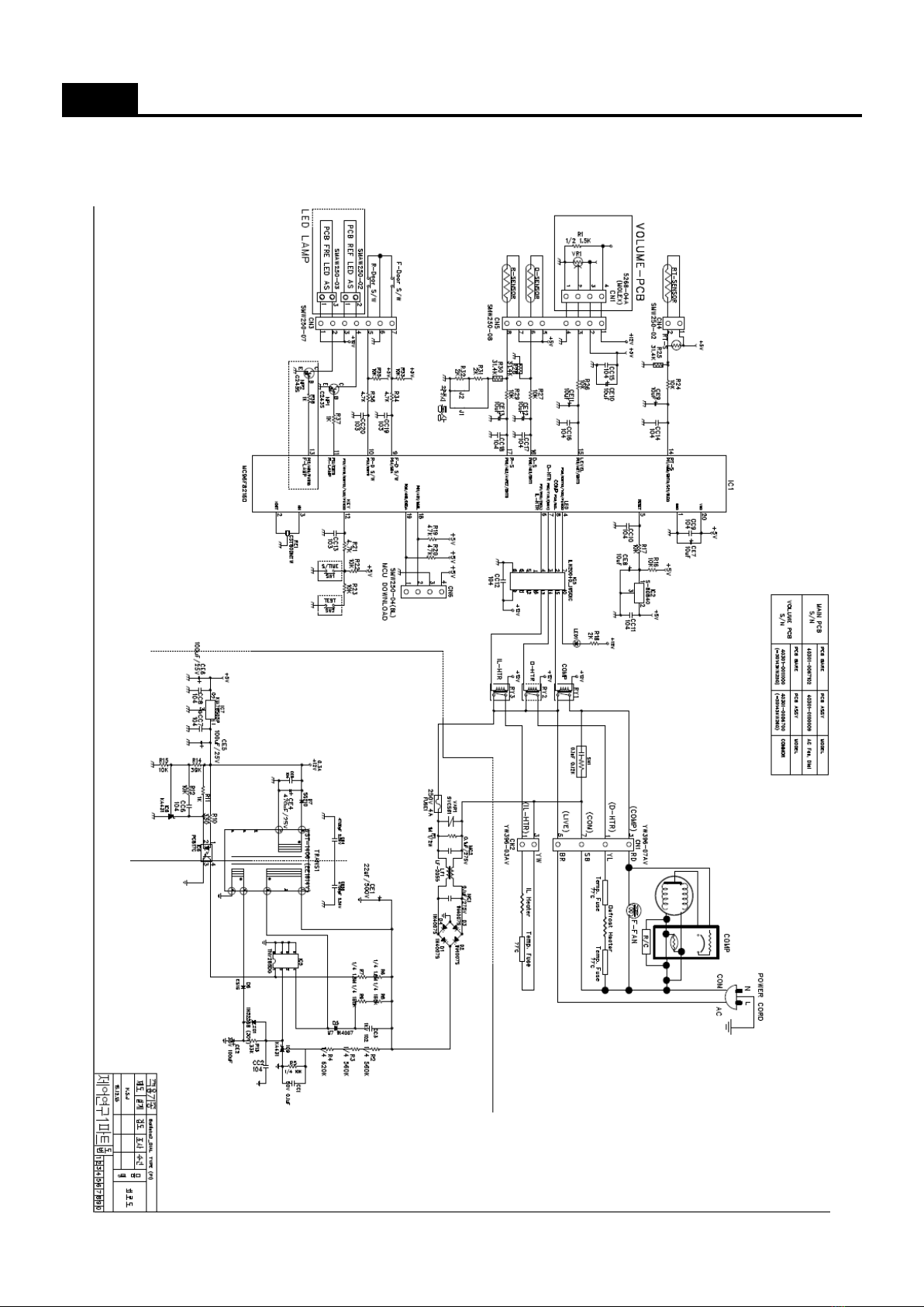
1-7. Main PCB Circuit Diagram ---------------------------------------------------------------------------------------------------------------------
9
2. FUNCTIONS
2-1. 'PCB VOLUME' Control --------------------------------------------------------------------------------------------------------------------13
2-2. Temperature Control of Refrigerator compartment -------------------------------------------------------------------------------- 15
2-3. Defrost Mode -------------------------------------------------------------------------------------------------------------------------------- 17
2-4. Function of Low Ambient Temperature ------------------------------------------------------------------------------------------------
2-5. Time Saving Function ----------------------------------------------------------------------------------------------------------------------------
2-6. Control of R Sensor OFF Point ----------------------------------------------------------------------------------------------------------------
2-7. Error Display --------------------------------------------------------------------------------------------------------------------------------------------
26
3. DISASSEMBLY
3-1. Door Switch --------------------------------------------------------------------------------------------------------------------------------- 28
3-2. Cover Multi-Flow Duct As (in Fresh food Compartment) ---------------------------------------------------------------------------
3-3. Louver F As (in Frozen Food Compartment) --------------------------------------------------------------------------------------------
3-4. Door F/R --------------------------------------------------------------------------------------------------------------------------------------------------
4. How to Change Door Position ------------------------------------------------------------------------------------------------------------------------
5. How to Charge R-600a Refrigerant ----------------------------------------------------------------------------------------------------------------
34
6. Part List -------------------------------------------------------------------------------------------------------------------------------------------- 39