Northland NL24WSG0 series Manual

EN Installation, Operation and Maintenance Instructions
FR Instructions d’installation, d’utilisation et d’entretien
ES Instrucciones de instalación, operación y mantenimiento
Wine refrigerator / cooler
Le vin réfrigérateur
Refrigerador para vinos
NL24WSG0**
Note: Wine refrigerators / coolers are designed
exclusively for the storage of wine. Wine refriger-
ators / coolers cannot attain storage temperatures
suitable for fresh food storage.
Remarque : Les réfrigérateur sont conçues exclu-
sivement pour y garder des vins. Elles ne peuvent
pas atteindre des températures de conservation
convenant à l’entreposage d’aliments frais.
Nota: Estas refrigerador están diseñadas
exclusivamente para el almacenamiento de vino.
Las refrigerador para vinos no pueden alcanzar las
temperaturas adecuadas para el almacenamiento
de alimentos frescos.
2
Important Safety Instructions
Warnings and safety instructions appearing in this
guide are not meant to cover all possible conditions
and situations that may occur. Common sense,
caution, and care must be exercised when install-
ing, maintaining, or operating this appliance.
RECOGNIZE SAFETY SYMBOLS,
WORDS, AND LABELS.
NOTE
!CAUTION
CAUTION- Hazards or unsafe practices which
could result in personal injury or property / product
damage.
NOTE- Important information to help assure a
problem free installation and operation.
Contents:
Safety information ..................................................2
Unpacking your wine cellar ...................................3
Warranty registration ...........................................3
Installing your wine cellar ......................................4
Cabinet clearances ..............................................4
Leveling the appliance .........................................4
Electrical connection ...........................................5
Installing the anti-tip device ....................................6
Product Dimensions ...............................................8
Using your Electronic control ................................10
Starting your wine cellar .....................................10
Turning your wine cellar "ON" or "OFF" .............10
Set the temperature ...........................................10
Wine cellar operation .........................................10
Alarms...............................................................10
Door ajar ........................................................10
Temperature sensor fault ...............................10
High and Low temperature ............................10
Alarm mute ........................................................10
Shelving congurations ........................................11
Care and cleaning ................................................12
Energy saving tips ................................................12
Obtaining service ..................................................13
Troubleshooting ....................................................14
Warranty ..............................................................15
CONTENTS
WARNING - You can be killed or seriously
injured if you do not follow these instructions.
!WARNING
State of California Proposition 65 Warning:
This product contains one or more chemicals
known to the State of California to cause birth
defects or other reproductive harm.
!WARNING
State of California Proposition 65 Warning:
This product contains one or more chemicals
known to the State of California to cause
cancer.
!WARNING
3
NOTE
!CAUTION
Figure 1
Remove Interior Packaging
Your appliance has been packed for shipment with
all parts that could be damaged by movement se-
curely fastened. Remove internal packing materials
and any tape holding internal components in place.
The owners manual is shipped inside the product
in a plastic bag along with the warranty registration
card, and other accessory items.
Important
Keep your carton and packaging until your appli-
ance has been thoroughly inspected and found to
be in good condition. If there is damage, the pack-
aging will be needed as proof of damage in transit.
Afterwards please dispose of all items responsibly.
Note to Customer
This merchandise was carefully packed and
thoroughly inspected before leaving our plant.
Responsibility for its safe delivery was assumed
by the retailer upon acceptance of the shipment.
Claims for loss or damage sustained in transit must
be made to the retailer.
DO NOT RETURN DAMAGED MERCHANDISE TO
THE MANUFACTURER - FILE THE CLAIM WITH
THE RETAILER.
If the appliance was shipped, handled, or stored
in other than an upright position for any period of
time, allow the appliance to sit upright for a period
of at least 24 hours before plugging in. This will
assure oil returns to the compressor. Plugging the
appliance in immediately may cause damage to
internal parts.
UNPACKING YOUR WINE CELLAR
Warranty Registration
It is important you send in your warranty registra-
tion card immediately after taking delivery of your
appliance.
The following information will be required when
registering your appliance.
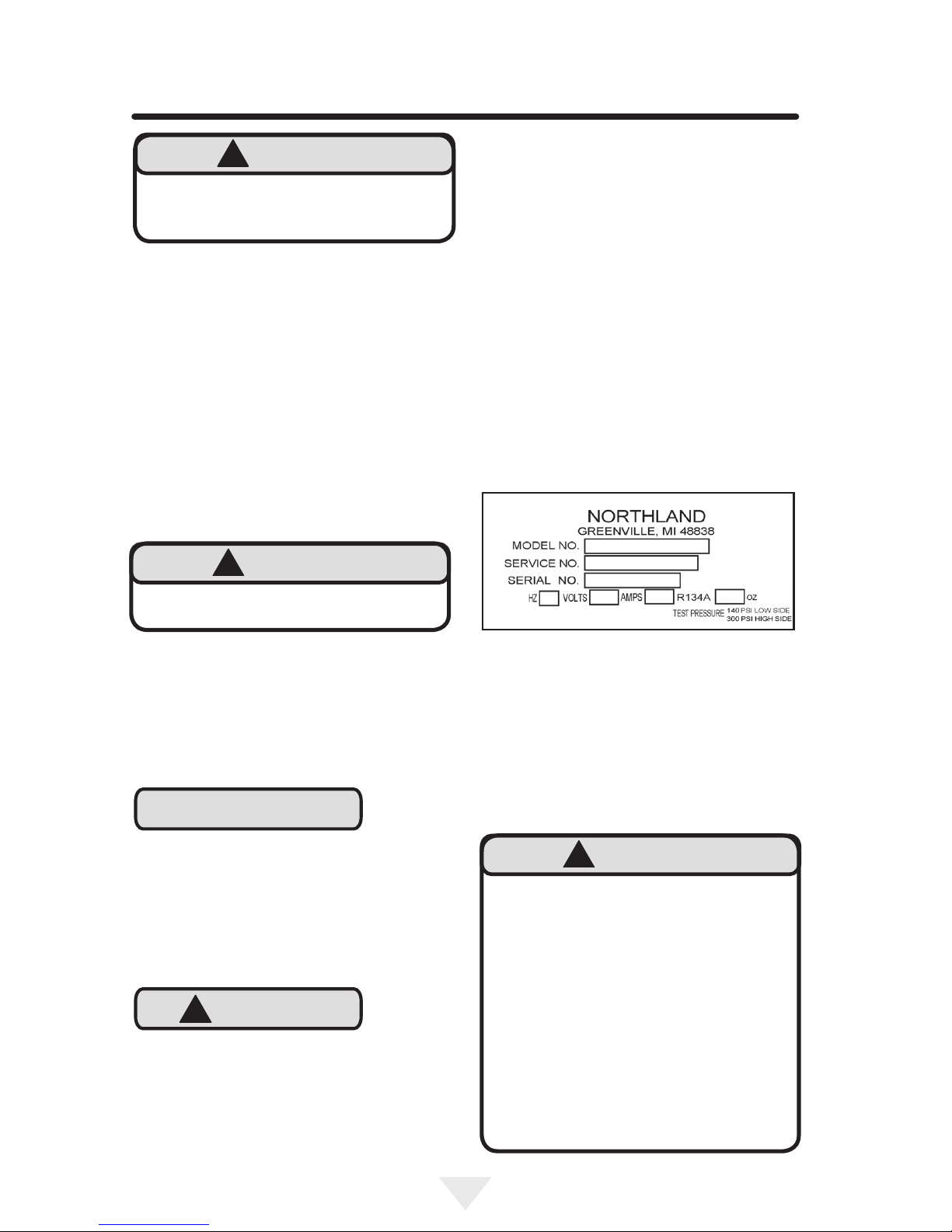
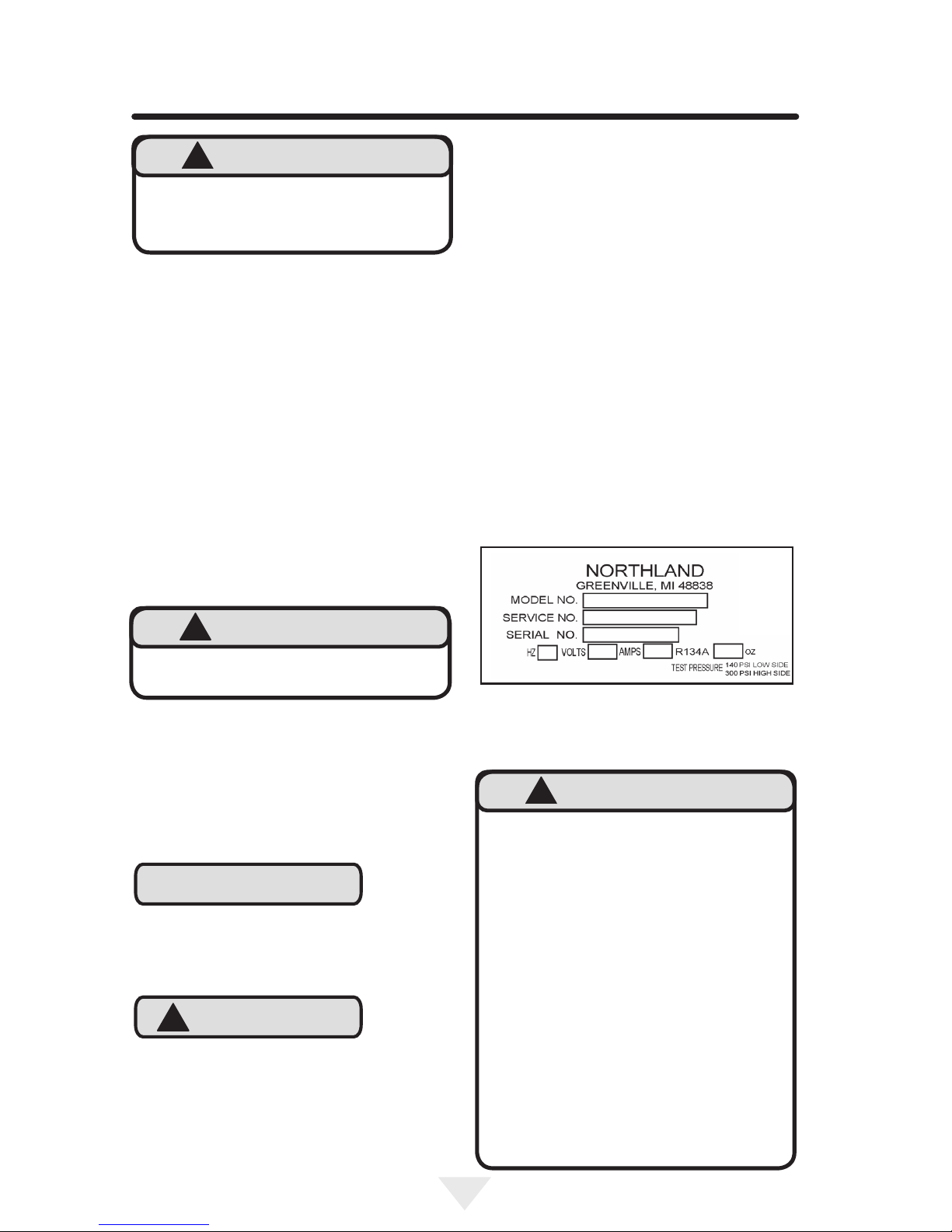
Service Number
Serial Number
Date of Purchase
Dealer’s name and address
The service number and serial number can be
found on the serial plate which is located inside the
cabinet on the left side near the top. (See gure 1).
WARNING - Help Prevent Tragedies
Child entrapment and suffocation are not
problems of the past. Junked or abandoned
refrigerators are still dangerous - even if they sit
out for "just a few hours".
If you are getting rid of your old refrigerator,
please follow the instructions below to help
prevent accidents.
Before you throw away your old refrigerator or
freezer:
• Take off the doors or remove the drawers.
• Leave the shelves in place so children
may not easily climb inside.
!WARNING
EXCESSIVE WEIGHT HAZARD
Use two or more people to move product.
Failure to do so can result in personal injury.
!WARNING
WARNING - Dispose of the plastic bags which
can be a suffocation hazard.
!WARNING

4
Select Location
The proper location will ensure peak performance
of your wine cellar. We recommend a location
where the unit will be out of direct sunlight and
away from heat sources. To ensure your product
performs to specications, the recommended
installation location temperature range is from 55 to
100°F (13 to 38°C).
Cabinet Clearance
Ventilation is required from the bottom front of the
wine cellar. Keep this area open and clear of any
obstructions. Adjacent cabinets and counter top
can be installed around the wine cellar as long as
the front grille remains unobstructed.
INSTALLING YOUR WINE CELLAR
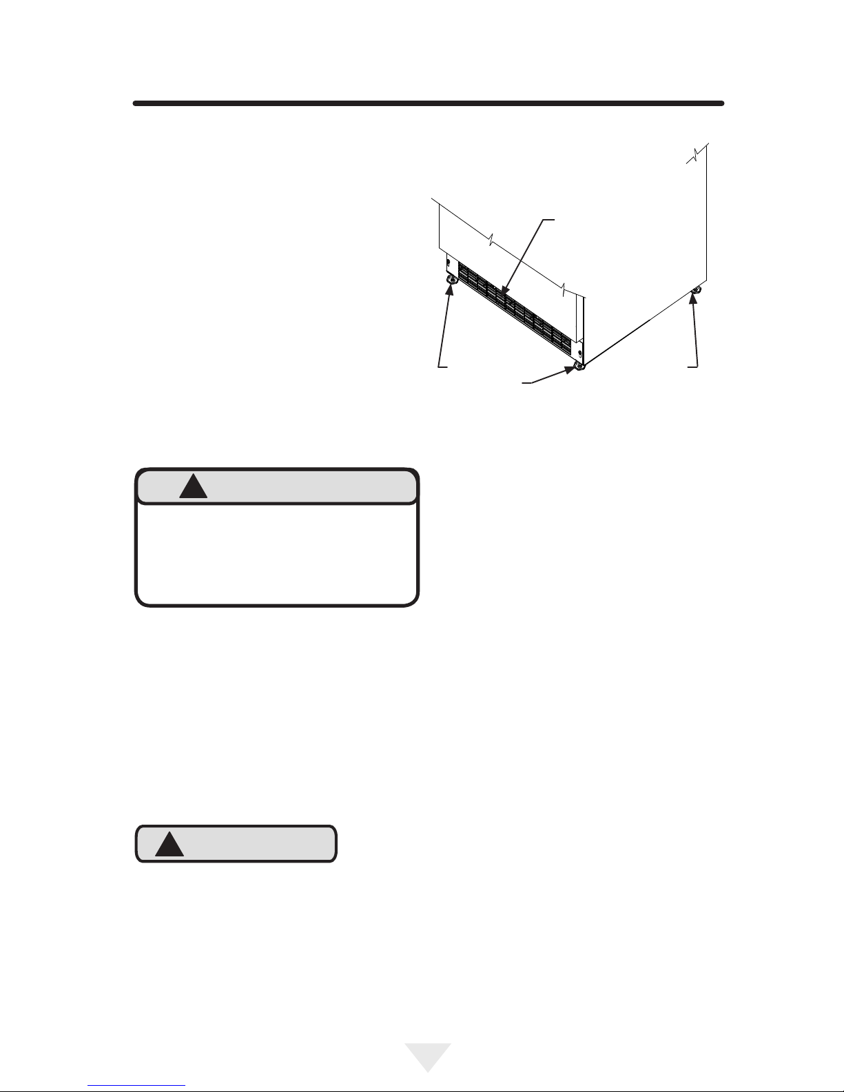
Front Grille
Do not obstruct the front grille. The openings within
the front grille allow air to ow through the con-
denser heat exchanger. Restrictions to this air ow
will result in increased energy usage and loss of
cooling capacity. For this reason it is important this
area not be obstructed and the grille openings kept
clean. Northland does not recommend the use of
a custom made grille as air ow may be restricted.
(See Figure 2).
!CAUTION
Leveling Legs
Adjustable legs at the front and rear corners of the
wine cellar should be set so the unit is rmly posi-
tioned on the oor and level from side to side and
front to back. The overall height of your Northland
wine cellar may be adjusted between the minimum,
333⁄4" (85.7 cm), by turning the leveling leg in (CW
↷) and the maximum, 343⁄4" (88.3 cm) by turning the
leveling leg out (CCW ↶).
To adjust the leveling legs, place the wine cellar
on a solid surface and protect the oor beneath
the legs to avoid scratching the oor. With the
assistance of another person, lean the wine cellar
back to access the front leveling legs. Raise or
lower the legs to the required dimension by turning
the legs. Repeat this process for the rear by tilting
the wine cellar forward using caution. On a level
surface check the wine cellar for levelness and
adjust accordingly.
The front grille screws may be loosened and the
grille adjusted to the desired height. When adjust-
ment is complete tighten the two front grille screws.
(See Figure 5).
Front Leveling
Legs
Figure 2
Rear
Leveling
Legs
Front Grille, keep
this area open.
An optional stacking kit, for 24" wide models,
is required to stack products. Failure to use a
stacking kit could result in personal injury. Con-
tact your dealer or Northland customer service
at 800-223-3900 to order.
!WARNING

5
INSTALLING YOUR WINE CELLAR
Figure 3
Figure 4
Do not remove
ground prong
Front grille screw
Front grille
Figure 5
Figure 6
Ground Fault Circuit Interrupters (GFCI) are prone
to nuisance tripping which will cause the appliance
to shut down. GFCI’s are generally not used on
circuits with power equipment that must run unat-
tended for long periods of time, unless required to
meet local building codes and ordinances.
NOTE
Electrical Connection
A grounded 115 volt, 15 amp dedicated circuit is
required.
This product is factory equipped with a power
supply cord that has a three-pronged, grounded
plug. It must be plugged into a mating grounding
type receptacle in accordance with the National
Electrical Code and applicable local codes and or-
dinances (see Figure 6). If the circuit does not have
a grounding type receptacle, it is the responsibility
and obligation of the customer to provide the proper
power supply. The third ground prong should not,
under any circumstances, be cut or removed.
Electrical Shock Hazard
• Do not use an extension cord with this ap-
pliance. They can be hazardous and can
degrade product performance.
• This appliance should not, under any cir-
cumstances, be installed to an un-ground-
ed electrical supply.
• Do not remove the grounding prong from
the power cord. (See Figure 3).
• Do not use an adapter. (See Figure 4).
• Do not splash or spray water from a hose
on the appliance. Doing so may cause
an electrical shock, which may result in
severe injury or death.
!WARNING
6
INSTALLING THE ANTI TIP DEVICE
FOR FREESTANDING INSTALLATIONS
NOTE
Anti-Tip Device
Floor Mount Installation
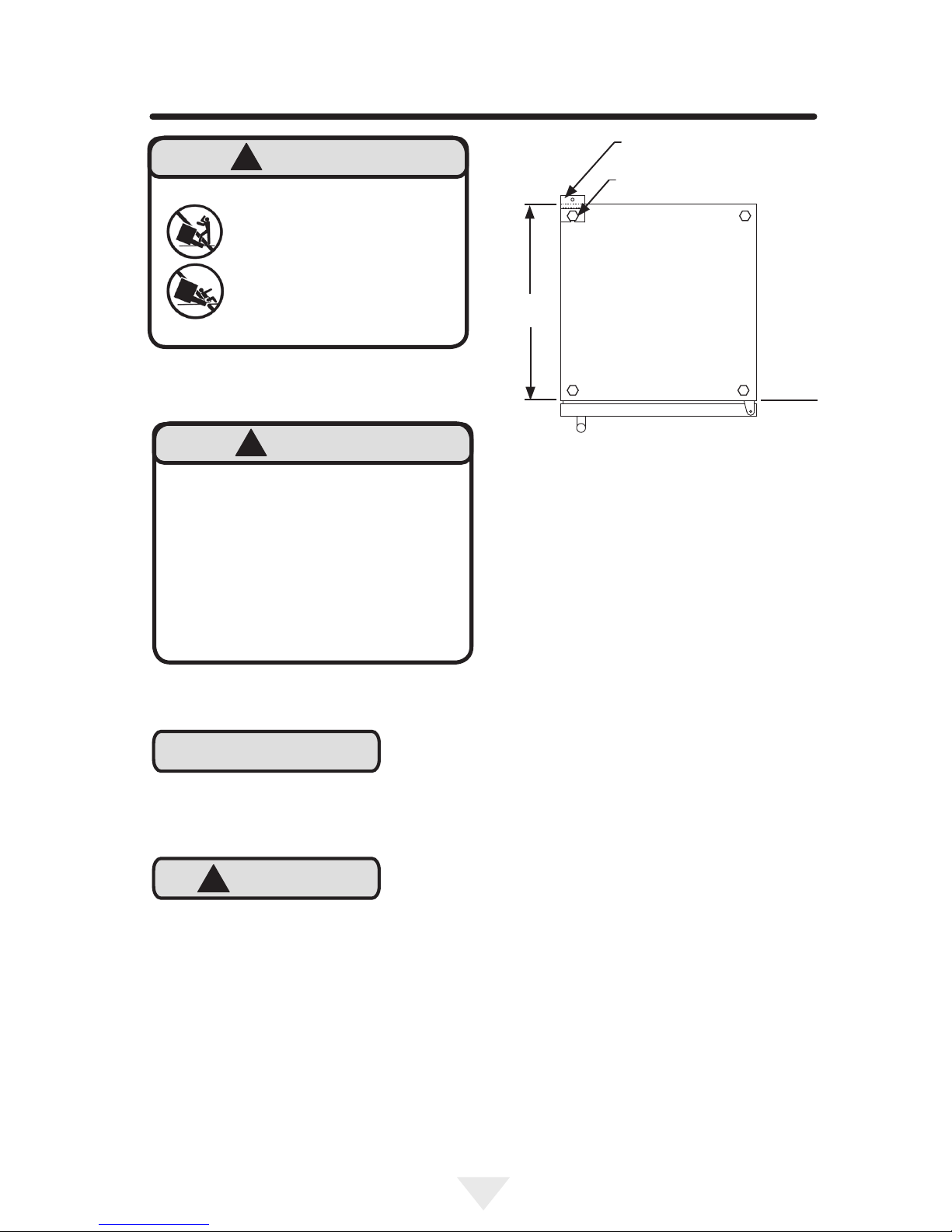
The anti-tip bracket is to be located on the oor
in the left or right rear corner of the wine cellar as
shown in Figure 7.
Any nished ooring should be protected with
appropriate material to avoid damage when moving
the unit.
If installing on a concrete oor, concrete fasteners
are required, (not included with the anti-tip kit).
!CAUTION
Bottom View of
Wine cellar
Anti-Tip
Bracket
Leveling Leg
Front of
cabinet
211⁄2"
(54.6 cm)
Figure 7
Step by step instructions for locating
the position of the bracket:
1) Decide where you want to place the wine cellar.
Slide it into place, being careful not to damage the
oor, leaving 1" (2.5 cm) of clearance from the rear
wall to allow room for the anti-tip bracket.
2) Raise the rear leveling legs approximately 1⁄4" (6
mm) to allow engagement with the anti-tip bracket.
Level the unit by adjusting all the leveling legs as
required. Turning the leveling leg counterclockwise
will raise the unit and clockwise will lower the unit.
3) Make sure the wine cellar is in the desired loca-
tion, then mark on the oor the rear and side corner
of the cabinet where the anti-tip bracket will be
installed. If the installation does not allow marking
the rear corner of the cabinet, then make temporary
lines on the oor marking the front corner of the
cabinet, excluding the door. Slide the wine cellar
out of the way. From the temporary line extend
the sidewall line back 211⁄2" (54.6 cm) as shown in
Figure 8.
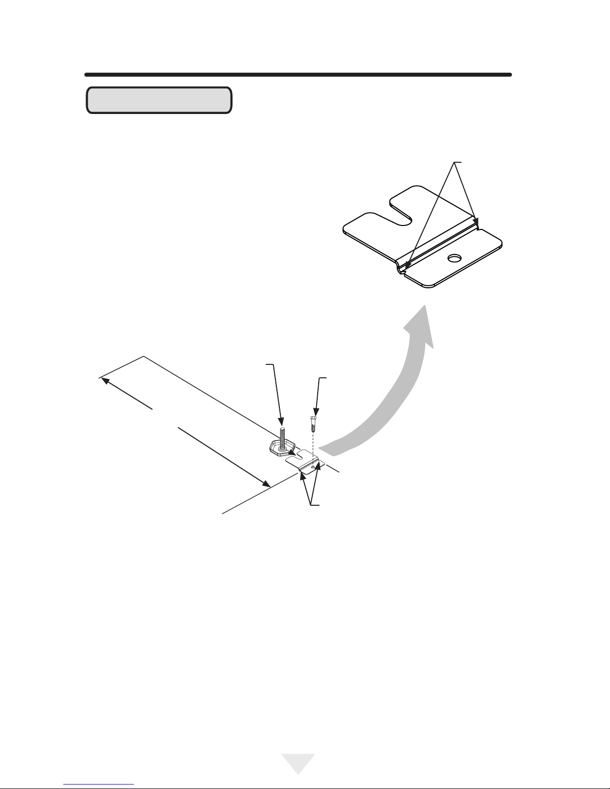
4) Align the anti-tip bracket to the marks on the oor
so the side of the bracket lines up with the side of
the cabinet mark, and the "V" notches on the an-
ti-tip bracket line up with the end of the 211⁄2" (54.6
cm) line (Rear of cabinet line).
5) Fasten the anti-tip bracket to the oor using the
supplied screw. (See Figure 8).
6) Slide the cabinet back into position, making sure
the rear cabinet leveling leg slides under the anti-tip
bracket engaging the slot.
• ALL APPLIANCES CAN TIP
RESULTING IN INJURY.
• INSTALL THE ANTI-TIP
BRACKET PACKED WITH
THE APPLIANCE.
• FOLLOW THE INSTRUC-
TIONS BELOW
!WARNING
If your wine cellar is not located under a count-
er top (free standing), you must use an anti-tip
device installed as per these instructions. If
the wine cellar is removed from its location
for any reason, make sure that the device is
properly engaged with the anti-tip bracket when
you push the wine cellar back into the original
location. If the device is not properly engaged,
there is a risk of the wine cellar tipping over,
with the potential for property damage or
personal injury.
!WARNING
7
INSTALLING THE ANTI TIP DEVICE
FOR FREESTANDING INSTALLATIONS
When the oor mounted anti-tip bracket is used
the minimum adjusted height of the cabinet is
increased by 3⁄8" (9 mm).
NOTE
211⁄2"
(54.6 cm)
"V" notches
in bracket
"V" notches
in bracket
Side of cabinet line
Figure 8
Front of cabinet line
Rear of cabinet line
Rear Leveling leg
Screw
Figure 8a
8
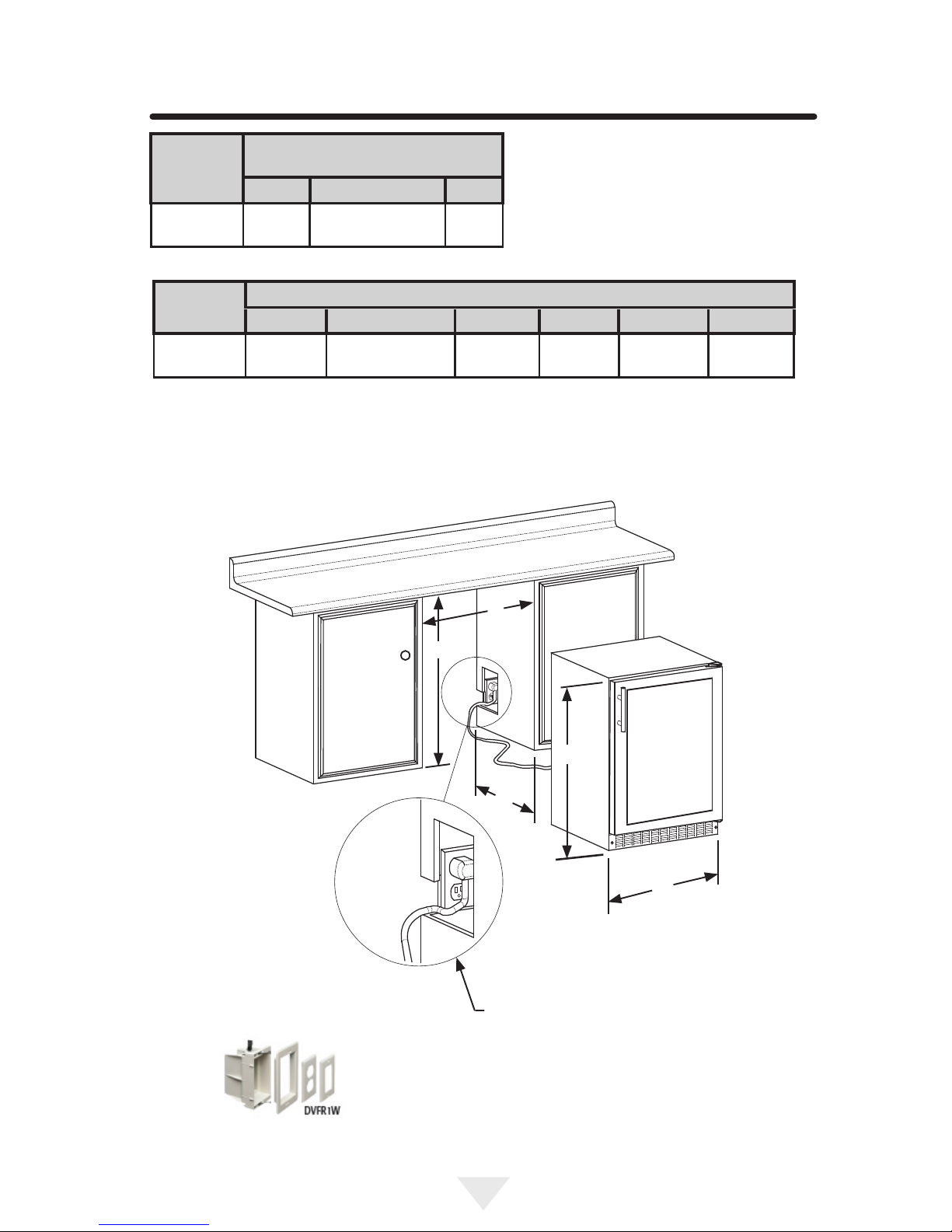
MODEL
ROUGH-IN OPENING
DIMENSIONS
"A" "B" "C"
NL24WSG 24"
(61 cm)
**34" to 35"
(86.4 to 88.9 cm) *
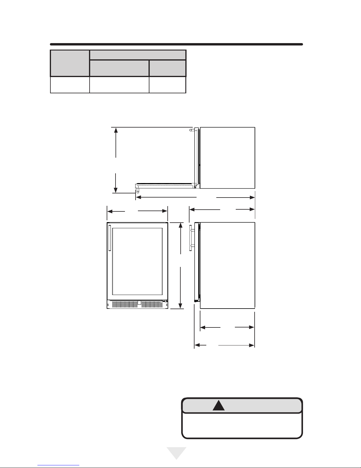
MODEL
CABINET DIMENSIONS
"D" "E" "F" "G" "H" "J"
NL24WSG 237⁄8"
(60.7 cm)
333⁄4" to 343⁄4"
(85.7 to 88.3 cm)
2323⁄32"
(60.2 cm)
247⁄8"
(63.2 cm)
4613⁄32"
(117.9 cm)
2429⁄32"
(63.3 cm)
PRODUCT DIMENSIONS
Figure 10
If necessary to gain clearance inside the rough-in
opening a hole can be cut through the adjacent cab-
inet and the power cord routed through this hole to a
power outlet. Another way to increase the available
opening depth is to recess the power outlet into the
rear wall to gain the thickness of the power cord
plug. Not all recessed outlet boxes will work for this
application as they are too narrow, but a recessed
outlet box equivalent to Arlington #DVFR1W is rec-
ommended for this application, (see Figure 10).
Figure 9
Figure 9a
"A"
"B"
"C"
"D"
"E"
9
MODEL
PRODUCT DATA
ELECTRICAL
REQUIREMENTS #
PRODUCT
WEIGHT
NL24WSG 115V/60Hz/15A 140 lbs
(63.6 kg)
PRODUCT DIMENSIONS
* Depth dimension of rough-in opening may vary
depending on each individual installation. To recess
entire door "F" dimension plus 1" (2.5 cm) for thick-
ness of power cord plug is required.
** Minimum rough-in opening required is to be
larger than the adjusted height of the cabinet.
# A grounded 15 amp dedicated circuit is required.
Follow all local building codes when installing elec-
trical and appliance.
"F"
211⁄2"
(54.6 cm)
"D"
"E"
"H"
"J"
"G"
Figure 11
Floor mount Anti-tip Bracket must be installed
for freestanding applications. Not required for
built in applications.
!WARNING
10
Starting your wine cellar
Plug the wine cellar power cord into a wall outlet.
Your wine cellar will begin cooling after power is
applied.
If your wine cellar does not start, check that the
wine cellar is turned on and the set temperature is
cold enough.
Turning your wine cellar ON or OFF
If the wine cellar is on, the wine cellar temperature
will be shown on the display. To turn the wine cellar
off, press and hold the "ON/OFF" button for three
(3) seconds. "OFF" will appear on the display.
If the wine cellar is not on, "OFF" will be shown on
the display. To turn the wine cellar on, press and
hold the "ON/OFF" button for three (3) seconds.
The wine cellar temperature will be shown on the
display.
Set temperature
To set the wine cellar temperature, press and
hold the "SET" button. When the "SET" button is
pressed, the display will show the set tempera-
ture. While holding the "SET" button, press the
"WARMER" or "COLDER" buttons to adjust set
temperature.
Wine cellar operation
The available temperature range of the wine cellar
is 40° to 65°F (4° to 18° C).
It may take up to 24 hours for your wine cellar to
reach desired temperature. This will depend on
amount of content loaded and number of door
opening and closings.
For best results allow wine cellar to "pull down"
to desired set temperature before loading. Once
contents are loaded, allow at least 48 hours for
temperature to stabilize before making any adjust-
ments to the set temperature.
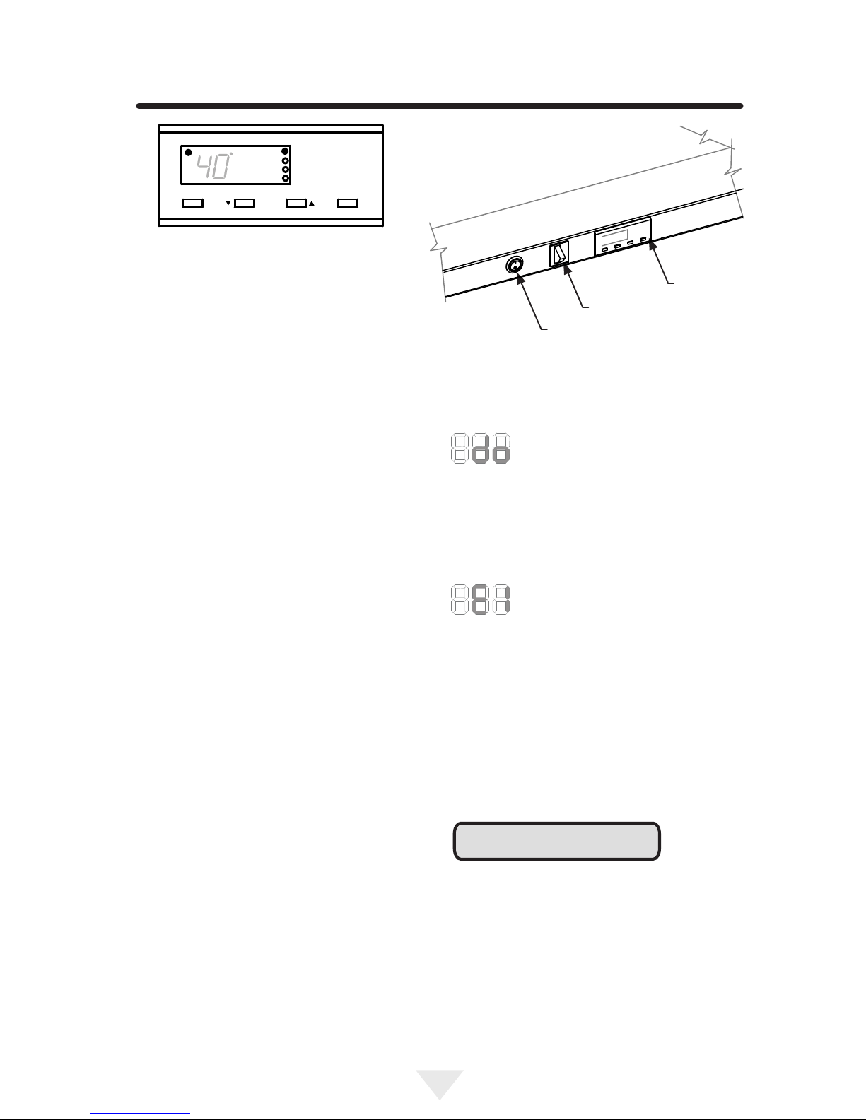
Alarms
Your control will monitor wine cellar function and
alert you with a series of audible and visual alarms.
•Door Ajar Alarm: If the door has
been left open for over ve (5)
minutes, the alarm will sound in one
(1) second intervals. The display panel will ash
"do" and the Alarm LED located at the top left of the
display below the word "Alarm" will be illuminated.
This will stop as soon as the door is closed.
•Temperature Sensor Fault: If the
controller detects that the tempera-
ture sensor is not properly function-
ing, a temperature sensor alarm will sound in one
(1) second intervals. "E1" will ash on the display
panel and the Alarm LED located at the top left of
the display below the word "Alarm" will be illuminat-
ed. Please call Northland Customer Service or your
dealer if this error code is displayed.
Set Colder Warmer ON/OFF
Press and Hold Press and Hold
Alarm
F
Figure 12
close-up of control
Figure 13
Control
Assembly
Door Switch
Light Switch
Control
Alarm Mute
Press any key to mute the audible portion of an
alarm.
This action will only mute the alarm. If the condition
that caused the alarm continues, the alarm code
will continue to ash and will sound for 20 seconds
every 60 minutes.
NOTE
USING YOUR ELECTRONIC CONTROL

11
SHELVING CONFIGURATIONS
Insert Wine Bottles
The four (4) pull-out shelves each hold eight (8)
bottles. See Figure 14 for typical wine bottle
spacing. Care should be taken when storing extra
tall bottles in the wine cradle at the bottom of the
compartment because they may prevent the door
from closing.
Loading Tips and Suggestions
Two (2) magnums can be placed in the bottle cradle
as long as they are positioned horizontally.
The bottles on the top rack directly under the light
will be exposed to a slightly higher temperature
when the light is on. Position your wines accord-
ingly and REMEMBER TO TURN OFF THE LIGHT
WHEN IT IS NO LONGER NEEDED.
Keep wines that you plan to use for everyday drink-
ing and entertaining on the front half of the racks
where labels are completely visible. Place wines
for aging or longer term storing in the rear.
Pull-out Racks
The four (4) pull-out wine racks may be pulled out
approximately seven and a half (7.5) inches to facil-
itate adding or removing bottles. DO NOT lean on
or press down heavily on the wine shelves. Doing
so may damage the shelves and the wine bottles
stored on them. Pull the wine racks out gently and
carefully to minimize unsettling your wine collection.
Avoid pulling out more than one rack at any time to
maintain stability.
Single Bottle Racks
The single level roll out racks allow you to easily
view and access your inventory without disturbing
other bottles (see Figure 16).
Figure 15
Figure 16
Front Bottles (Necks Facing Rear)
Rear Bottles (Necks Facing Front)
Figure 14

12
Front Grille
Be sure that nothing obstructs the required air ow
openings in front of the cabinet. At least once or
twice a year, brush or vacuum lint and dirt from the
front grille area (see page 4).
SHOCK HAZARD: Disconnect electrical power
from the appliance before cleaning with soap and
water.
Cabinet
The painted cabinet can be washed with either
a mild soap and water and thoroughly rinsed
with clear water. NEVER use abrasive scouring
cleaners.
Interior
Wash interior compartment with mild soap and
water. Do NOT use an abrasive cleaner, solvent,
polish cleaner or undiluted detergent.
Care of Appliance
1. Avoid leaning on the door, you may bend the
door hinges or tip the appliance.
2. Exercise caution when sweeping, vacuuming
or mopping near the front of the appliance.
Damage to the grille can occur.
3. Periodically clean the interior of the appliance
as needed.
4. Periodically check and/or clean the front grille
as needed.
In the Event of a Power Failure
If a power failure occurs, try to correct it as soon
as possible. Minimize the number of door openings
while the power is off so as not to adversely affect
the appliance's temperature.
Light bulb replacement
!CAUTION
CARE AND CLEANING, ENERGY SAVING TIPS
The following suggestions will
minimize the cost of operating your
refrigeration appliance.
1. Do not install your appliance next to a hot
appliance (cooker, dishwasher, etc.), heating
air duct, or other heat sources.
2. Install product out of direct sunlight.
3. Ensure the front grille vents at front of
appliance beneath door are not obstructed
and kept clean to allow ventilation for the
refrigeration system to expel heat.
4. Plug your appliance into a dedicated power
circuit. (Not shared with other appliances).
5. When initially loading your new product, or
whenever large quantities of warm contents
are placed within refrigerated storage com-
partment, minimize door openings for the next
12 hours to allow contents to pull down to
compartment set temperature.
6. Maintaining a relatively full storage compart-
ment will require less appliance run time than
an empty compartment.
7. Ensure door closing is not obstructed by
contents stored in your appliance.
8. Allow hot items to reach room temperature
before placing in product.
9. Minimize door openings and duration of door
openings.
10. Use the warmest temperature control set
temperature that meets your personal prefer-
ence and provides the proper storage for your
stored contents.
11. When on vacation or away from home for
extended periods, set the appliance to warm-
est acceptable temperature for the stored
contents.
12. Set the control to the "off" position if cleaning
the appliance requires the door to be open for
an extended period of time.
To replace the light bulb, disconnect power to the
unit. Unscrew the old light bulb located behind
the display housing at the top of the unit. Set the
old light bulb aside. Screw the new light bulb into
place. Reconnect power to the unit. Check to see
if the light bulb operates properly to complete the
installation.
The light bulb is not covered by your warranty. A
replacement bulb can be obtained from your dealer
or from Northland.
The wine cellar uses one, 25 watt incandescent
light bulb to illuminate the interior. The light bulb is
a very reliable electrical component, but should it
not function properly, please call the dealer where
you purchased your wine cellar from for a replace-
ment light bulb. Use only an original equipment
light bulb from your dealer or Northland.
DISCONNECT THE POWER CORD BEFORE
ATTEMPTING LIGHT BULB REPLACEMENT.
Failure to do so may result in an electrical
shock that could severely injure you.
Do NOT under any circumstance use a light
bulb that exceeds 25 watts!
!WARNING

13
If Service is Required:
• If the product is within the rst year warranty
period please contact your dealer or call
Northland Customer Service at 800-223-
3900 for directions on how to obtain warranty
coverage in your area.
• If the product is outside the rst year warranty
period, Northland Customer Service can
provide recommendations of service centers
in your area.
• In all correspondence regarding service, be
sure to give the service number, serial num-
ber, and proof of purchase.
• Try to have information or description of
nature of the problem, how long the appliance
has been running, the room temperature, and
any additional information that may be helpful
in quickly solving the problem.
• Table "A" is provided for recording pertinent
information regarding your product for future
reference.
For Your Records
Date of Purchase
Dealer’s name
Dealer’s Address
Dealer’s City
Dealer’s State
Dealer’s Zip Code
Appliance Serial Number
Appliance Service Number
Date Warranty Card Sent (Must
be within 10 days of purchase).
Table A
OBTAINING SERVICE

14
TROUBLESHOOTING
!CAUTION
Before You Call for Service
If the appliance appears to be malfunctioning, read
through this manual rst. If the problem persists,
check the troubleshooting guide below. Locate the
problem in the guide and refer to the cause and
its remedy before calling for service. The problem
may be something very simple that can be solved
without a service call. However, it may be required
to contact your dealer or a qualied service tech-
nician.
In the unlikely event you lose cooling in your unit,
do not unplug the product from the electric
supply, but do call a qualied service technician
immediately. It is possible that the loss of cooling
capacity is a result of excessive frost build-up on
the evaporator cooling coil. In this case, removing
power to the unit will result in the melting of this
excessive quantity of ice, which could generate
melt water that exceeds the capacity of the defrost
drain system and could result in water damage to
your home. The end-user will be ultimately respon-
sible for any water damage caused by prematurely
turning the unit off without appropriately managing
the excess water run-off.
Problem Possible Cause Remedy
Appliance not cold enough
(See "Set temperature" on
page 10)
• Control set too warm
• Content temperature not
stabilized.
• Excessive usage or pro-
longed door openings.
• Airow to front grille
blocked.
• Door gasket not sealing
properly.
• Adjust temperature colder. Allow
24 hours for temperature to
stabilize.
• Allow temperature to stabilize for
at least 24 hours.
• Airow must not be obstructed
to front grille. See "clearances"
on page 4.
• Replace door gasket.
Appliance too cold
(See "Set temperature" on
page 10)
• Control set too cold
• Door gasket not sealing
properly.
• Adjust temperature warmer.
Allow 24 hours for temperature
to stabilize.
• Replace door gasket.
No interior light. • Light bulb is burned out • Replace light bulb, see page 12.
Light will not go out when
door is closed
• Door not activating light
switch.
• Failed light switch
• Appliance not level, level
appliance, (See page 4, "leveling
legs")
• Contact a qualied service
technician.
Noise or Vibration • Appliance not level
• Fan hitting tube obstruc-
tion.
• Level appliance, see "Leveling
Legs" on page 4.
• Contact a qualied service
technician.
Appliance will not run. • Appliance turned off
• Power cord not plugged in.
• No power at outlet.
• Turn appliance on. See "Starting
your wine cellar" on page 10.
• Plug in power cord.
• Check house circuit.
• Never attempt to repair or perform mainte-
nance on the appliance until the main electrical
power has been disconnected. Turning the
appliance control "OFF" does not remove
electrical power from the unit's wiring.
• Replace all parts and panels before operating.
Electrocution Hazard
!WARNING

15
HOUSEHOLD PRODUCT WARRANTY
Entire Product
Limited One Year Parts and Labor
Warranty
Northland warrants that it will supply all necessary
parts and labor to repair or replace in the end
user’s home or ofce, any component which proves
to be defective in material or workmanship, subject
to the condition and exclusions stated below, for a
period of one year from the date of purchase by the
end user.
Additional Second Through Fifth
Year
Limited Parts Only Warranty
During the four years following expiration of the one
year limited warranty, Northland will supply replace-
ment parts for the hermetically sealed refrigeration
system which consists of the compressor, condens-
er, drier, accumulator, bypass valve, connecting
tubing and the evaporator that are proven to be
defective due to workmanship or materials subject
to the conditions and exclusions below.
The above warranties do not cover:
• Shipping costs of replacement parts or
returned defective parts.
• Customer education or instructions on how to
use the appliance.
• Any content loss due to product failure.
• Removal or installation of product.
Nor do the above warranties cover failure of this
product or its components due to:
• Transportation or subsequent damages.
• Commercial use or use other than normal
household or small ofce.
• Improper installation, misuse, abuse, accident
or alteration, use of wiring not conforming to
electrical codes, low or high voltages, failure
to provide necessary maintenance, or other
unreasonable use.
Parts or Service
Not Supplied or Designated by North-
land
The above warranties also do not apply if:
• The original bill of sale, deliver date, or serial
number cannot be veried.
• Defective parts are not returned for inspection
if so requested by Northland.
• The refrigeration equipment is not in the pos-
session of the original end use purchaser.
The warranties set forth herein are the only warran-
ties extended by Northland. Any implied warranties,
including the implied warranty of merchantability,
are limited to the duration of these express warran-
ties. In no event shall Northland be liable for any
consequential or incidental damages or expenses
resulting from breach of these or any other warran-
ties, whether express or implied.
Some states do not allow the exclusion or limitation
of consequential damages or a limitation on how
long an implied warranty lasts, so the above exclu-
sion or limitation may not apply to you. This warran-
ty gives you specic legal rights and you may have
other rights that may vary from state to state.
No person, rm, or corporation is authorized to
make any other warranty or assume any other obli-
gation for Northland. These warranties apply only to
products used in any of the fty states of the United
States and the District of Columbia.
To obtain performance of this warranty, report any
defects to:
Northland
1260 E. VanDeinse St.
Greenville MI 48838
Phone: 800-223-3900

All specications and product designs subject to
change without notice. Such revisions do not entitle
the buyer to corresponding changes, improve-
ments, additions, replacements or compensation
for previously purchased products.
Northland
1260 E. VanDeinse St.
Greenville MI 48838
800-223-3900
41014823-EN Rev B
4/20/17

EN Installation, Operation and Maintenance Instructions
FR Instructions d’installation, d’utilisation et d’entretien
ES Instrucciones de instalación, operación y mantenimiento
Wine refrigerator / cooler
Le vin réfrigérateur
Refrigerador para vinos
NL24WSG0**
Note: Wine refrigerators / coolers are designed
exclusively for the storage of wine. Wine refriger-
ators / coolers cannot attain storage temperatures
suitable for fresh food storage.
Remarque : Les réfrigérateur sont conçues exclu-
sivement pour y garder des vins. Elles ne peuvent
pas atteindre des températures de conservation
convenant à l’entreposage d’aliments frais.
Nota: Estas refrigerador están diseñadas
exclusivamente para el almacenamiento de vino.
Las refrigerador para vinos no pueden alcanzar las
temperaturas adecuadas para el almacenamiento
de alimentos frescos.
2
CONTENU
Contenu :
Informations de sécurité..........................................2
Déballage de votre appareil ...................................3
Enregistrement de la garantie ............................3
Installation de votre appareil ..................................4
Dégagements par rapport à l’armoire ...................4
Mise à niveau de l’appareil ...................................4
Raccordement électrique.....................................5
Installation du dispositif anti-basculement..............6
Dimensions du produit............................................8
Utilisation de votre commande électron..............10
Congurations de étagères ...................................11
Entretien et nettoyage ..........................................12
Conseils pour l’économie d’énergie .....................12
Obtention de service ............................................13
Dépannage..........................................................14
Garantie................................................................16
REMARQUE
!ATTENTION
Importantes instructions de sécurité
Les avertissements et les instructions de sécurité
qui apparaissent dans ce guide n’ont pas la préten-
tion de couvrir toutes les conditions et situations
possibles pouvant arriver. Il faut faire preuve de
bon sens, de précautions et de soins, pour installer,
utiliser ou entretenir cet appareil.
Reconnaissance des symboles, des mots et des
étiquettes concernant la sécurité.
ATTENTION - Risques ou pratiques dangereuses
pouvant entraîner des blessures individuelles, des
dégâts matériels ou des dommages au produit.
REMARQUE - Information importante pour réaliser
une installation et une utilisation sans problèmes.
AVERTISSEMENT - Risque possible de décès
ou de blessure grave si vous ne suivez pas les
instructions.
!AVERTISSEMENT
Avertissements de la proposition 65 de l'État
de Californie : Ce produit contient au moins un
produit chimique connu par l’État de Californie
pour être à l’origine de malformations et autres
déciences de naissance.
!AVERTISSEMENT
Avertissements de la proposition 65 de l'État
de Californie : Ce produit contient au moins un
produit chimique connu par l’État de Californie
pour être à l’origine de cancers.
!AVERTISSEMENT
3
Figure 1
REMARQUE
!ATTENTION
Enregistrement de la garantie
Il est important que vous postiez votre carte de
garantie immédiatement après avoir pris livraison
de votre cellier.
Les informations suivantes seront nécessaires au
moment de l’enregistrement de votre appareil :
Numéro de service
Numéro de série
Date d’achat
Nom et adresse du revendeur
Le numéro de service et le numéro de série se
trouvent sur la plaque signalétique qui est située à
l’intérieur de l’armoire, du côté gauche près du haut
(Voyez la Figure 1).
Enlèvement de l’emballage intérieur
Votre cellier a été emballé pour l’expédition avec
toutes les pièces pouvant être endommagées par
le mouvement solidement attachées. Enlevez les
matériaux d’emballage intérieur et toute bande
maintenant des composants intérieurs en place.
Le manuel de l’utilisateur est envoyé à l’intérieur
de l’appareil dans un sac en plastique, accompag-
né de la carte d’enregistrement de la garantie, et
d’autres articles accessoires.
Important
Conservez votre carton d’emballage jusqu'à ce que
votre cellier ait été complètement inspecté et trouvé
en bon état. S’il présentait des dommages, cet
emballage serait nécessaire comme preuve qu’ils
sont survenus durant le transit. Ensuite veuillez
mettre tous ces matériaux d’emballage au rebut
d’une façon responsable.
Note pour le client
Cette marchandise a été soigneusement et
complètement inspectée avant de quitter notre
usine. La responsabilité pour sa livraison sûre a été
assumée par le revendeur à l’acceptation de cette
expédition. Les réclamations pour perte ou dom-
mages survenus durant le transit sont à adresser
au revendeur.
NE RENVOYEZ PAS DE MARCHANDISE EN-
DOMMAGÉE AU FABRICANT – DÉPOSEZ UNE
RÉCLAMATION AUPRÈS DU REVENDEUR.
Si l’appareil a été livré, manipulé ou entreposé
dans une position autre que debout, pendant
une durée quelconque, laissez-le reposer debout
pendant au moins 24 heures avant de la brancher
électriquement. Cela assurera le retour de l’huile au
compresseur. Un branchement immédiat de l’appa-
reil pourrait endommager des parties internes.
DÉBALLAGE DE VOTRE APPAREIL
AVERTISSEMENT - Contribuez à éviter des
tragédies
L’emprisonnement d’enfants et leur asphyxie ne
sont pas des problèmes du passé. Des épaves
de réfrigérateurs abandonnés continuent de
présenter un danger - même en restant dehors
pour «juste quelques heures».
Si vous devez vous débarrasser de votre vieil
appareil de refroidissement, veuillez suivre ces
instructions pour aider à éviter des accidents
possibles.
Avant de jeter votre vieux réfrigérateur ou
congélateur :
• Démontez ses portes ou enlevez ses
tiroirs.
• Laissez les étagères en place de façon à
ce que des enfants ne puissent pas facile-
ment monter dedans.
!AVERTISSEMENT
AVERTISSEMENT - Jetez bien les sacs en plas-
tique qui représentent un risque de suffocation.
!AVERTISSEMENT
AVERTISSEMENT
RISQUE DE POIDS EXCESSIF
Utilisez deux personnes ou plus pour déplacer le
produit. Sinon vous pourriez vous blesser.
!AVERTISSEMENT
4
Figure 2
INSTALLATION DE VOTRE APPAREIL
!ATTENTION
Pieds de mise à
niveau avant
Pieds de
mise à niveau
arrière
Grille frontale, gardez
cette zone dégagée.
Grille frontale
N’obstruez pas la grille frontale. Les ouvertures au
travers de la grille frontale permettent l’écoulement
de l’air par l’échangeur thermique du condenseur.
Des restrictions de ce ux d’air vont augmenter la
consommation d’énergie et affecter sa capacité de
refroidissement. C’est pourquoi il est important que
cette zone ne soit pas obstruée et soit maintenue
propre. Northland recommande de ne pas utiliser
de grilles personnalisées, car l’écoulement d’air en
serait diminué (Voyez la Figure 2).
Pieds de mise à niveau
Des pieds réglables aux angles avant et arrière
de l’armoire doivent être ajustés pour qu’elle soit
fermement positionnée au sol et bien d’aplomb,
d’un côté à l’autre et d’avant en arrière. La hauteur
totale de votre appareil Northland peut être ajustée
entre le minimum 333⁄4po (85,7 cm) (en vissant les
pieds de mise à niveau CW ↷) et le maximum 343⁄4
po (88,3 cm) (en dévissant les pieds de mise à
niveau CCW ↶) des.
Pour régler ces pieds de mise à niveau, placez
l’appareil sur une surface solide, en protégeant le
sol en dessous pour ne pas le rayer. Avec l’aide
d’une autre personne, inclinez vers l’arrière de
l’appareil pour accéder aux pieds de mise à niveau
de l’avant. Levez ou abaissez ces pieds à la hau-
teur requise en les tournant. Répétez la procédure
pour les pieds arrière en inclinant le cave à vin vers
l’avant en faisant attention. Sur une surface plane,
vériez le niveau de l’appareil et ajustez les pieds
en conséquence.
Les vis de la grille frontale peuvent être desserrées
et la grille ajustée à la hauteur voulue. Quand le
réglage est fait resserrez les vis de la grille frontale
(Voyez la Figure 5).
Choix de l’emplacement
Un bon emplacement assurera une performance
de pointe pour votre appareil. Nous recomman-
dons un endroit où l’appareil ne sera pas exposé
directement au rayonnement solaire et restera
écarté de sources de chauffage. Pour assurer que
les performances de votre produit soient au niveau
de ses spécications, la plage de températures
recommandée au lieu d’installation sera de 55 à
100°F (13 à 38 °C).
Dégagements par rapport à l’armoire
Une ventilation est nécessaire depuis la section
frontale du bas de l’armoire. Gardez cette zone
libre et exempte de toutes obstructions. Des
meubles et comptoirs peuvent être installés autour
de l’unité de façon adjacente dans la mesure où sa
grille frontale restera non obstruée.
Un kit optionnel d’empilage est nécessaire pour
empiler des produits. Le fait de ne pas utiliser
de kit d’empilage peut entraîner une blessure
corporelle. Contactez votre revendeur ou le
service à la clientèle de Marvel au 800-223-3900
pour le commander.
!AVERTISSEMENT
Table of contents
Languages:


