7
SmartCraft gateways Installation and Operation Manual NAVMAN
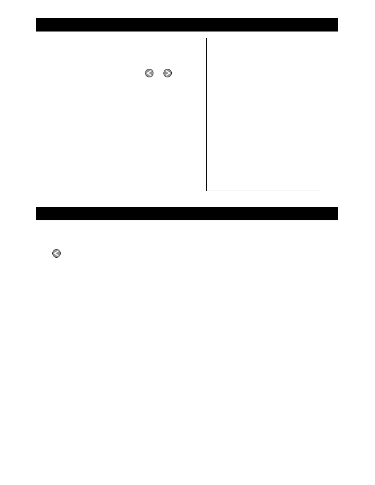
Power/fuel splitter
cable (‘Y’ cable)
Plug gateway into
white connector Other wiring,
refer to the
instrument’s
manual
Plug gateway into
white connector
Other wiring,
refer to the
instrument’s
manual
For a Navman instrument without a white fuel
sensor connector (such as a FISH 4380):
For a Navman instrument with a white fuel sen-
sor connector (such as a FISH 4600 or TRACKFISH
6600):
The wires from the gateway to the Navman
instrument cable can be connected to the
instrument’s power/data cable. This option is not
normally necessary. For more information, refer to
your Navman dealer.
For any Navman instrument, using a NavBus junction box to connect to power/data cable (black
power connector):
Cut white connector off gateway cable. Connect
five gateway cable wires (red, black, blue, orange,
brown) to the same colour wires in the power/
data cable. An optional Navman NavBus junction
box simplifies wiring.
Other wiring,
refer to the
instrument’s
manual
NavBus
junction box
FISH 4600,
TRACKFISH
6600
FISH 4380
2-2 Connecting the gateway to the Navman instrument
Power/data
cable
1 Plan the installation: select where the equip-
ment and wiring will be installed. Ensure
that gateway can be located on a panel near
the Navman instrument, where it will not
interfere with the operation of the boat. (eg:
cables are long enough for the installation
planned)
2 Screw the gateway to the panel using the
screws provided.
3 Connect the gateway (see sections 2-1 and
2-2). Secure the cables at regular intervals.
4 Power up, set up and test the system. Check
the gateway LEDs:
NAV (orange): Flashes fast when gateway is
exchanging data with the Navman instru-
ment and the engine key is on.
PWR (green): On when power and the engine
key are on.
CAN (red): Flashes fast when gateway is ex-
changing data with the SmartCraft engine(s)
and the engine key is on.
2-3 Installation
Important:
1 Do not connect any Navman fuel sensors to
the Navman instrument.
2 It is not necessary to wire any Navman instru-
ment for auto power on.
3 The Navman SmartCraft capable instrument
sends SmartCraft data to other
Navman instruments connected by NavBus.
To connect other instruments by NavBus, see
the instrument’s installation and operation
manual. Turn NavBus on in all Navman instru-
ments connected by NavBus; for example, for
a Fish 4380, in the Comms setup menu, turn
NavBus to On.
4 A gateway does not provide data for system
link gauges.
5 To use speed troll control, the Navman instru-
ment must have a Navman paddlewheel
speed sensor connected.