NorthStar M157310C User manual

M157310C
Installation, Operation, and Maintenance Manual
HOT WATER PRESSURE WASHER: Cleans dirty surfaces with high
pressure hot water.
To the Owner:
Thank you for purchasing a NorthStar hot water pressure washer. Your machine is designed for long life,
dependability and the top performance you demand! Take time now to read through this manual so you better
understand the machine’s operation, maintenance and safety precautions. Everyone who operates this machine
must readand understand this manual. The time you take nowwill prolong your machine’s life and prepare you
for its safe operation. Enjoy the exceptional performance of your NorthStar hot water pressure washer, the
industry leader! The manufacturer reserves the right to make improvements in design and/or changes in
specifications at any timewithout incurringany obligation to install them on units previously sold.
Quick Facts
Engine Oil Engine is shipped withoutoil. Fill beforestarting.
Use SAE 10W-30 motor oil.
Pump Oil Pump is shipped with oil. Remove shipping tape and check pump oil level before
starting. Use SAE 30 Non-detergentpump oil (item # 4043) or CatPump Oil (item
#22158) for oil changes.
Water Make sure your water flow is 20% higher than the pressure washer’s flow rate.
Make sure your water is clean and particle free.
Storage Do notallow water to freeze in the pump,hose,coil,or spraygun.
Spraying
Chemicals Use anyNorthStar brand or equivalentpressure washer chemicals.
Adjustsoap adjustmentknob to regulate cleaning power.
Maintenance
Schedule Engine: Oil: change after first20 hours,then annuallyor every100 hours.
Spark Plug:clean every100 hours,replace annuallyor every 300 hours.
AirFilter:clean every100 hours,replace annuallyor every300 hours.
Pump: Oil: change after first40 hours,then every3 months or500 hours.
Read and understand all manuals before operating.
Any Questions, Comments, Problems or Parts Orders
In the UnitedStates In the United Kingdom
Northstar Customer Service Call 02392639752
Call 1-800-270-0810 Northern Tool and Equipment Co. (UK) Ltd.
Hours: Monday - Friday 7:00 AM to5:30 PM Unit 2, Keel Close,
Saturday 7:30 AM-11:30 AM Central Time Portsmouth, Hants PO3 5QD, England
ITEM NUMBE
R
: 157310
SERIAL NUMBER:
Engine Model:
Pump Model:
Flow: Pressure:
Hose Length: Lance Length:
Nozzle Size:

Table of Contents
Important Safety Instructions 2Maintenance Instructions 12-15
Specifications 3 Moving and Handling Instructions 16
Machine Component
Identification 4LongTerm Storage 16
Installation Instructions 5-8 Troubleshooting 17
OperationInstructions 9-11 PartsBreakdowns 18-20
Safety Features 12 Electrical Schematic 21-23
Important Safety Instructions
WARNING -Riskof injection or injury to persons - Do not direct discharge stream at persons. - Do not use
hose if exterior damage isevident.
-Riskof explosion. Donotspray flammableliquids. Do notoperatein a flammable environment.
CAUTION -Riskof asphyxiation. Exhaust fumesaredeadly. For outdoor use only. Avoid inhaling exhaust
fumes.
-Riskof fire. Donot add fuel when theproductisoperatingor hot.
-Gun kicksback, hold withboth hands.
-To reduce the riskof injury, read and understandoperatinginstructionscarefullybefore use.
WARNING - When using thisproductbasic precautionsshouldalwaysbe followed,includingthe following:
1.) Read all theinstructionsbefore usingthe product.
2.) To reduce theriskof injury, close supervision is necessary when the product is used near children. Do
not allow irresponsible use by children. Always stop the product and bleed pressures before leaving
unattended, disconnecting hoses, or servicing the pump.
3.) Knowhow to stoptheproductand bleed pressuresquickly. Be thoroughlyfamiliar with the controls.
4.) Stayalert - watch what you are doing.
5.) Do not operate the product when fatigued or under the influence ofalcohol or drugs. Never smoke while
operating or fuelingthismachine.
6.) Keep operating area clearof all persons.
7.) Do not overreach or stand on unstable support. Keep good footing and balance at all times. Wear
footwear capable of maintaining a good grip on wet surfaces - Do not place the machine on soft or
unstableground.
8.) Follow the maintenance instructions specified in all manuals. Do not run machine without sufficient
lubricationorsufficient waterto cool thepump.
9.) Wear safety glasses, gloves, faceprotection and appropriate clothing when operatingthemachine.
10.) Do not operate this machine with broken or missing parts. - Never alter the manufacturer’s original
design ordeactivateany safetydeviceon themachine.
11.) Risk of exposure to dangerous chemicals. Wear protective gloves when handling and cleaning with
chemicals. Follow the chemical manufacturer’sdirections. Understand all safetyhazardsand first aid for
all chemicals being used. Check whether dangerous chemicals have been used and take any
precautionsthatmayhave been recommended by the supplierof these chemicals when cleaning filters.
Do not pump highly abrasivefluidsor use withincompatible chemicalsor solvents.
12.) Know thepressure andtemperature limitsof your machine. Besure all high pressure accessories meet
or exceed yourmachine’slimits. Do notset the pressure relief valveabovethemachine’slimit.
13.) Do not move this machine by pulling on the hose. Do not use the pump to support other items of
equipmentthatimpose unacceptable loadson thepump. Do notattempttouse thismachineasa prop.
14.) Toreduce risk of injury, do not secure the spray gun open. Your spray gun is equipped with a built-in
trigger safety latch to guard against accidental trigger release and potentially dangerous high pressure
spray. Rotate the safetylatch to the locked position whennot spraying.
15.) Do not clean this machine with its own spray. Cleaning should be done with a damp sponge with the
engine OFF.
16.) NEVER attemptto immediately runor re-light theburnerifitdoesn’t ignite the first time. Unburned oil or
gasmayhave accumulated causing potential explosion or fire hazard.
17.) Alwaysmake sure all switchesand controlsare in theOFF position prior tostarting theengine.
SAVE THESE INSTRUCTIONS

3
Specifications
ITEM 157310
Pressure Rating 3000 psi
Flow Output 4 gpm
Pump Type Cat66DX
Water Supply Standard tap water @20-75
psi
Engine Horsepower 13 hp
BTU Output 353,700 BTU
Temperature Rise 140°F
Maximum Temperature 210°F
Approved Fuels #1 or #2 Diesel,Kerosene,
Fuel Oil
Fuel Capacity 8.5 Gal
Gasoline Capacity 8.5 Gal
Discharge Hose 3/8” X50’
Dimensions
Length 64”
Width 33”
Height 44”
Weight (shipping) 655 lbs
Weight (dry) 557 lbs
Weight (fueled) 710 lbs

4
Machine Component Identification
Ref # Description Ref # Description
1 Exhaust Vent 7FuelCap
2Pump 8 Fuel Tank
3BatteryBox 9 Control Panel
4 Fuel Filter/WaterSeparator 10 Engine
5GasCap 11 Burner
6 GasTank

5
Installation Instructions
I.) Unpack
Yourpressure washer is shippedononepallet. Separateand identifythe componentsand use theassemblyinstructions
in this manual forassembly.

6
Hardware Bag
6X Nozzle
4X Wheel
Retaine
r
6X Grommet
4Ft Braided
Hose
1X Strainer
Owner’
s
Manual
Honda Manual
4X - 5/16X 3/4” Flange Bolt
4X - 5/16Flange Nut
1X Chemical
Injector

7
II.) Assembly Instructions
III.) Pump Preparation
A.) Remove shippingtapeandmake sure theoil is1/2
way up oil sight glass.
IV.) Engine Preparation
A.) Fill engine with 1.16qtof oil.
B.) Fill fuel tank with unleaded gasoline, 86 octane min.
Quantities Of Fluid
Engine/Pump Type of Fluid QTY
Honda GX390 SAE10W30 1.16 qt (1.1L)
Cat 66DX SAE30** 18oz (0.55L)
**SAE Non-Detergent (Item# 4043)
V.) Battery
Warning: Sulfuric acid is a corrosive poison.
Avoid contact with skin, eyes or clothing. Always
wear safety glasses when working on or near the
battery.
The battery box providesprotection for thebattery and
will accepta standard lawn tractor size battery (Group
U1-7). The engine requiresa12-voltbattery, with a
minimum rating of 18 Ah (Amp-hour). When installing a
battery, alwaysconnect the red colored (“positive”or “+”)
cable first. When disconnecting a battery, always
remove the black colored (“negative” or “-”) cable first.
LIFT BACK OF UNIT BYHANDLESTOINSTAL
L
REAR WHEELS, THEN LIFT FRONT OF UNIT TO
INSTALL FRONT WHEELS
INSTALL WHEEL ONTO AXLE
FASTEN WHEEL WITH RETAINER,
SECURERETAINER WITH WRENCH PROVIDED
NOTE:IT ISRECOMMENDED THAT TWO PEOPLE
LIFT THIS UNIT WHILE ATHIRD SLIDESTHE
WHEELS ONTO THE AXLES
PRESS BRAIDED HOSE ONTO
INJECTOR AND STRAINER
FASTEN HANDLES TO FRAME WITH
5/16 X 3/4” BOLT S AND 5/16 NUTS
INSTALL GROMMETS
AND NOZZLESINTO
HOLES IN FRAME

8
VI.) Getting Started
IMPORTANT: Proper initial installation of equipment
will assure more satisfactory performance, longer
service life, and lower maintenance cost.
Make sure the pressure washerison alevel surface and
ina protected area where it is not readily influenced by
outside forces such as strong winds, freezing
temperatures, rain, etc. Locate the pressure washer for
easy access for filling fluids, adjustments, and
maintenance.
HOTWATER
HEAT CONTROLTE MP
It isrecommended thata partition be made between the
wash area and the pressure washer to prevent direct
nozzle spray from coming in contact with the pressure
washer. Moisture reaching the equipment will reduce
thepressure washer’s service life.
VII.) Venting
DANGER: Do not run machine indoors, in an
enclosed area, or in areas where flammable vapors,
(gasoline, solvents, etc.) may be present.
VIII.) Oil Burner
Burner Air Adjustment: The oil burner is preset and
performance tested at the factory (elevation 1100 feet).
Different altitudes may require a one-time initial burner
correction.
1.) Turn the engine and heat switches ON (Refer to
“Operation” fordetails). Have someone operate the
spray gun so the burner fires.
2.)Loosen thelocking screw and close theair band until
blacksmoke appears from the burner exhaust vent.
Note thepositionof the whitearrow onthe air band.
3.)Slowly open theairbanduntil white smoke just starts
to appear.
4.) Turn the air band half way back to the black smoke
position previously noted. Tighten the locking
screw.
5.) Fine tune theburner air by loosening the shutter lock
screw and turning the shutter until the exhaust is
cleanest. Tighten the shutterlockscrew.
CAUTION: If white smoke appears from the burner
exhaust vent during start-up or operation,
discontinue use and readjust air bands.
Locking
Screw
A
ir Band
Burner
White
Arrow
Shutte
r
LockScrew
Shutte
r

9
Operating Instructions
Read and understand the entire manual before operating the pressure washer.
Follow these instructions every time you use the pressure washer.
I.) Pre-Operation
;A.) Position the machine for easy access to all
controls.
;B.) Position the machine on a solid surface, with
less than a three degree slope, and so it is
protectedfrom external damage.
;C.) Position the machine so that ambient lighting is
sufficient for the surface you are cleaning to be
seen with ease. Use artificial lightif needed.
;D.) Checkhoses, fittings, wand,trigger gun and fuel
connections for signs of wear, cracks and
looseness, and replaceasrequired.
;E.) Checkand clean the nozzle orifice.
;F.) Check and clean the water inlet screen and
filter.
;G.) Read entire manual, especially the important
safety instructionslistedon page2.
;H.) Check and maintain proper oil levels in the
pumpand engine.
II.) Check Your Water Supply
;A.) Make sure the water supplyisclean. Debriscan
cause excess pump wear and reduce
performance.
;B.) An insufficient water supply will damage your
pump. Make sure the water supply is steady
and is 20% over the rated flow of your pump.
Use a stopwatchto timehowlongit takesto fill a
5 gallonbucket with yourgardenhose.
Example: If the ratedflowis= 4gpm
Then required flow= 4 x1.20= 4.8gpm
5gallons/ 4.8gpm =1.04minutes
1.04min x 60sec/min = 62 seconds
Therefore, youmust be able to fill a
5 gallonbucketin62 secondsor faster.
;C.) The water supply garden hose must have an
inside diameter of at least 5/8”. If the hose is
morethan100 ft. long, the diameter must be at
least 3/4”.
;D.) Never use a reservoir tank as a water source.
This pressure washer is designed for a
pressurized water source such as a city water
faucet. Sucking water out of a tank may cause
pump cavitation and damage to your pump.
However, the inlet pressure of the pump must
notexceed75 psi (5.25bar).
;E.) Alwaysuse a flexible rubber hose for your water
supply. Donotuse rigid piping.
;F.) Do not pump flammable liquids or liquids
containing incompatible chemicalsor solvents.
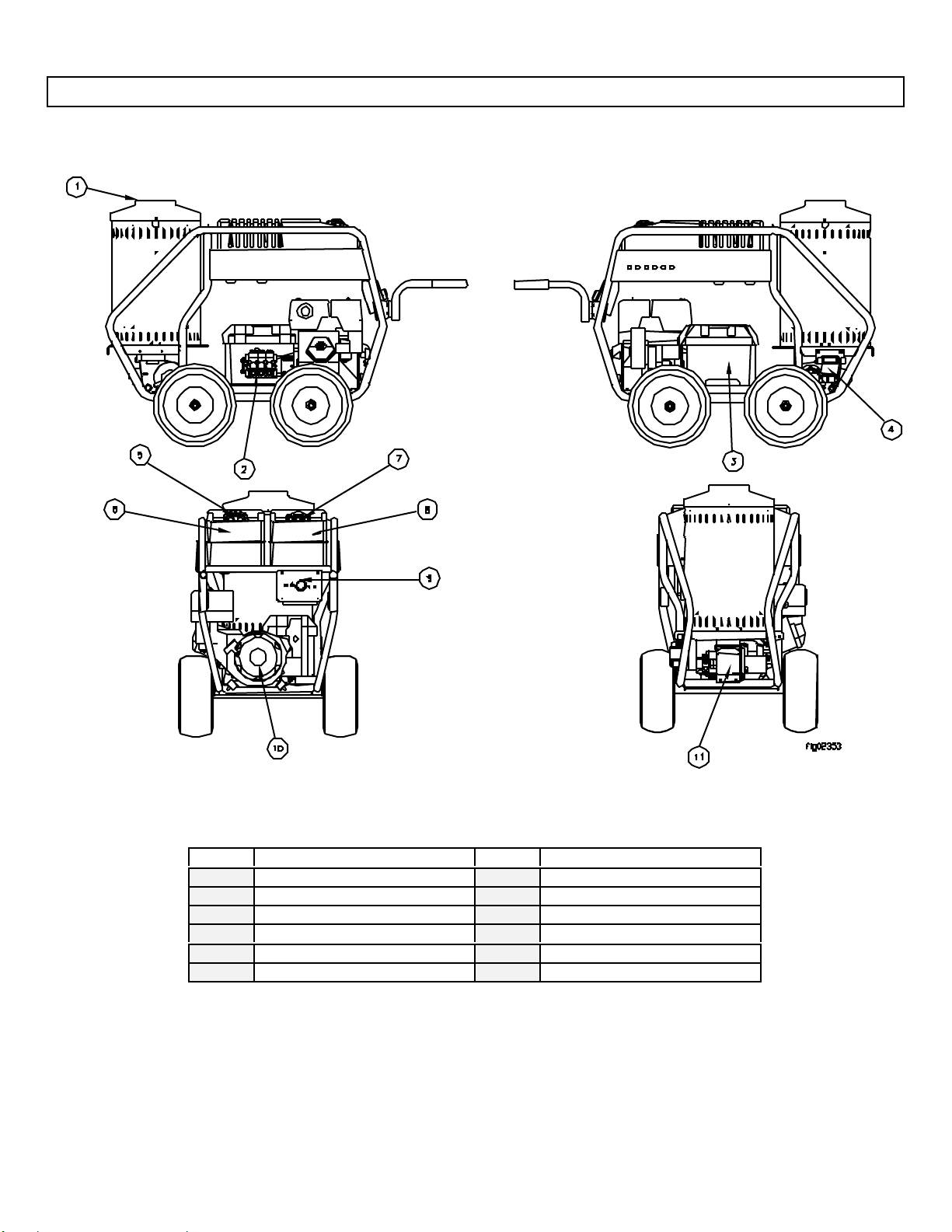
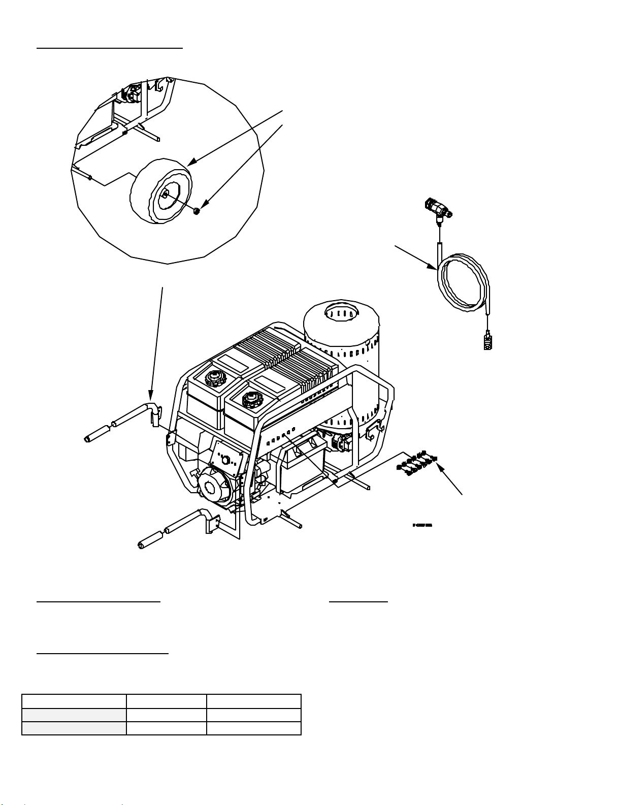
III.) Attach Garden Hose
Remove shipping plug from pump inlet and confirm
rubber washer is in place. Attach garden hose to water
inlet. See Machine ComponentIdentification forlocation
of water inlet.
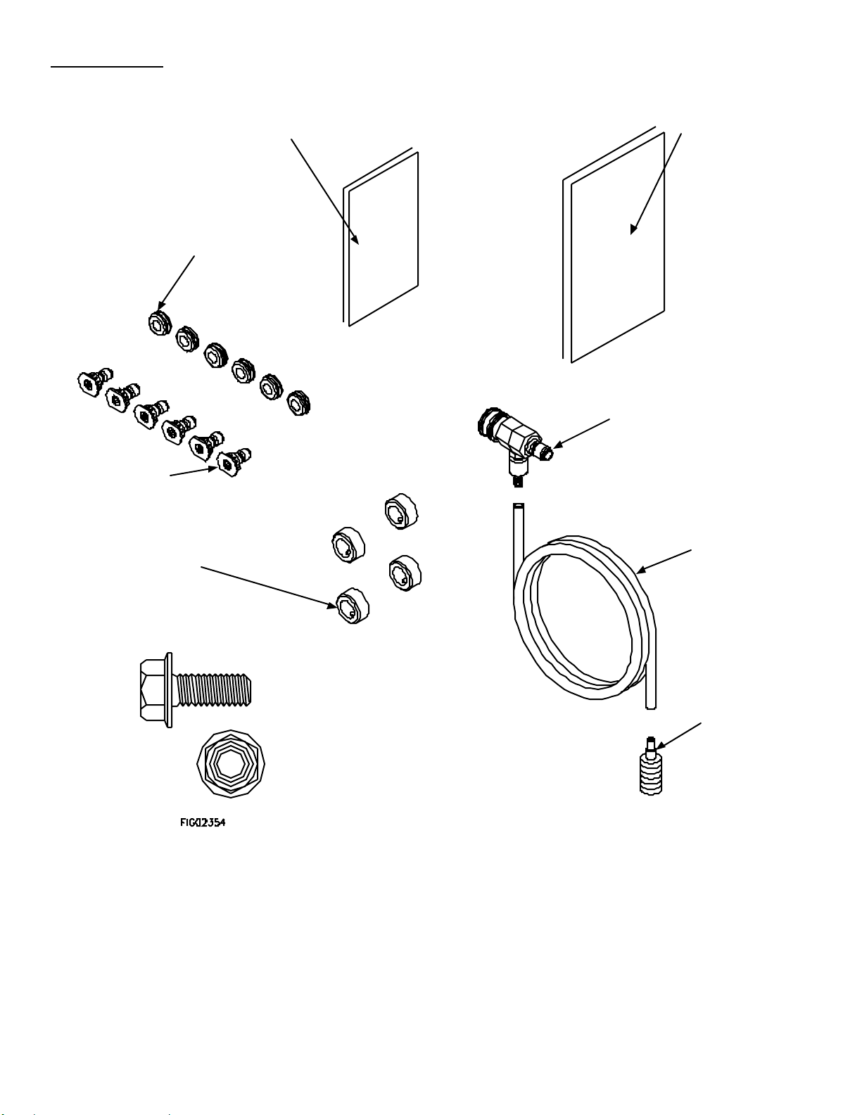
IV.) Attach High Pressure Hose
Your pressure washer hose is equipped with quick
couplers. Simply pull the collar back and push the
coupler onto the nipple. Make sure the collar slides over
theball bearings. Oncethe connection is made, pull on
thehose to assure a positive connection.
Colla
r
Couple
r
High Pressure
Output
CORRECT INCORRECT

10
Nozzle
V.) Turn Water Supply ON
Make sure the hose is not “kinked”. A kinked hose will
provide insufficient water supply to the pump and will
reduce its life. Make sure the hose remains unkinked
aftermoving thepressure washer.
VI.) Squeeze Trigger
Squeeze the trigger until a steady flow of water sprays
outthe nozzle. Make sure all the air is out of all hoses
before running the pressure washer. This step is very
important,it will prolong the pump’slife. NEVER run the
pumpdry.
VII.) Attach Nozzle
Color of Nozzle: Spray Angle Used For:
Red 0 Highest Impact
Yellow 15 Tough Stains/
Stripping
Green 25 General
White 40 LightCleaning
Black 65 Chemicals
Yellow #4.5 Steam
Your pressure washer is equipped with four high
pressure nozzles.To install a nozzle pull back the collar
and push the nozzle into the coupler. Once the
connection ismade, pull on the nozzle to assure a tight
connection.
WARNING: Make sure the nozzle is correctly
inserted. The nozzle may become a projectile if not
inserted correctly. Do not attempt to use different
types of nozzles that may not fit the coupler.
VIII.) Applying Chemicals
WARNING: Only use NorthStar pressure washer
chemicals or chemicals specifically formulated for
pressure washers. Follow the chemical
manufacturer’s recommendations. Understand all
safety precautions and first aid forallchemicals.
NOTE: Your pressure washer is equipped with a low
pressure chemical injector. The proper chemical
used for the proper application can speed up
cleaning jobs tremendously.
A.) Snap the quick couple chemical injector onto the high
pressure outlet and high pressure hose and submerge
the suction strainerinto the chemical solution.
B.) You need to use the low pressure nozzle to spray
chemicals onto the cleaning surface.
C.) Squeeze the spray gun trigger. The chemical
injector will draw the chemical into the waterstream
D.) Apply chemicals evenly to the cleaning surface.
Allow the chemicals to react with the dirt, then clean at
high pressure withgreennozzle.
E.) Never usemorechemical than is necessary to clean
the surface.
F.)If you do not intend on using chemicals, we suggest
removing the chemical injector to obtain maximum
cleaning pressure.
Max chemical ratiois13:1
Straine
r
CORRECT
Chemical Injector
INCORRECT
High Pressure Hose
Nozzle
Collar Coupler
00322
High Pressure
Output
Lance
Diluted
Chemical
AdjustmentKnob

11
IX.) Start Engine
*Refer to the engine manual to start your
engine.
IMPORTANT: The water must be turned on before
starting. Running the pump dry will cause damage
and void the warranty.
IMPORTANT: Make sure the fuel shutoff valve
located under the fuel tank is in the ON position.
WARNING: Check that there are no leaks in the
vicinity of the pump before starting engine.
Once the engine is started, begin cleaning. If the engine
doesn’t start on the first try, pressure maybuild up in the
pump. Relieve the pump pressure by squeezing the
spray gun trigger.Thiswill make starting easier.
WARNING: Do not inhale the exhaust from the
engine. Do not point the lance atanyone even if the
engine has stopped because there could be a
release of water under retained pressure if the spray
gun trigger is actuated.
X.) For Hot Water
1. IfHOT water isdesired, make sure there is fuel in the
fuel tank, turn the heat switch ON, and adjust the
thermostat to the desired temperature. The burner will
fire when the trigger is squeezed. You may need to
initially adjust your burner for peak performance. See
the “Oil Burner” section under INSTALLATION. When
the trigger is released or the temperature setting is
reached, the burner will automatically turn off.
IMPORTANT: Do not run the machine in hot mode
without any fuel in the fuel tank. The fuel pump will be
damagedifitis run dry.
XI.) Cleaning
WARNING: Wear eye, ear, hand, foot and skin
protection at all times while operating this pressure
washer.
DANGER: Do not point the spray wand at yourself or
at any person. Bodily injury may result from water
under high pressure.
CAUTION: Be careful on painted or delicate
surfaces. The pressure may damage the surface if
the nozzle is too close.
IMPORTANT: Your spray gun is equipped with a
built-in trigger safety latch to guard against
accidental trigger actuation and potentially
dangerous high pressure spray. Rotate the safety
latch to the locked position when notspraying.
A.) Hold thelance with two hands, havea sturdy stance.
B.) Pointlance atdirty surface and squeeze trigger.
C.) Wash from the bottom to the top, using side to side
motions. Thiswashesaway heavydirt andallowsthe
detergent to soakasyou worktoward thetop.
D.) Use the widthofthe spray pattern to wash in a wide
path. Overlap spraypathsforcomplete coverage.
E.) The nozzle shouldbe 12”to 24” from the work, closer
for tough areas.
F.) Small parts should be washed in a basket so the
pressure does not push them away. Larger, light
weightpartsshould be clamped down.
G.) The pressure washer is set and locked to the
maximum rated pressure when it leaves the factory.
There isaneasy way toadjust your pressure.
a. Turn the unloader knob (red handle on pump)
counterclockwise.
WARNING: Do not alter the unloader valve’s
maximum pressure. Excess pressures could cause
serious injury and/or pump damage. Any alteration
other than turning the adjustment knob will void
your warranty.
XII.) Shut-Down Instructions
WARNING: Do not leave an operating machine
unattended. Always shut the machine OFF and
relieve the pressure before leaving the machine.
Never disconnect the high pressure hose from the
pump or spray gun while the system is pressurized.
Depressurize the system by squeezing the spray
gun trigger after the engine is turned OFF.
A.) Turnheat switchOFF and run coldwater through the
coil for 3 minutes.
B.) Turn engine OFF.
C.) Turn water supply OFF.
D.) Actuate spray gun triggerto relieve system pressure.
E.) Removegarden hose.
F.)Remove pressure hose.
00417 Safet
y

12
Safety Features
I.) Safety Relief
The safetyrelief valve is a backup safety feature. If the
unloader malfunctions, the safety relief valve will open
andrelieve system pressure.
WARNING: If the safety relief valve ever discharges
water, turn the engine off and do not use the
machine. See a dealer or call Customer Service at
1-800-270-0810.
II.) High Temperature Limit
There isa high temperature limit using the thermometer.
If the discharge water overheats, the unit will shut down.
Maintenance Instructions
WARNING: Unauthorized machine modification or use of non-approved replacement parts may cause personal
injury and/or property damage and will void the manufacturerwarranty.
All mechanical equipment,nomatter how well designed, will need repairs. A North Star pressure washer is no exception.
At times, a North Star pressure washer may be inoperable because repairs are required. North Star Customer Service
will assist in these repairs as needed, but if an inoperable pressure washer creates a major expense to your business
then we strongly recommend the following:
1. Have someone on staff who istrainedin theoperation of the pressure washer and is capable of making minor repairs
andperforming all preventativemaintenance proceduresasoutlinedin theprovidedmanuals.
2. Keep a stockof recommended service partsformaintenanceand minor repairs.
Recommended Service Parts List
Following isa list ofthe service partswe recommend
stocking.
Description Part Number
0°Nozzle 253092
15°Nozzle 253093
25°Nozzle 777844
40°Nozzle 778737
Chemical Nozzle 778949
Steam Nozzle 778945
O-Ring for Hose 30784
Pump Oil 4043
Chemical Injector 31935
Spray Gun 31915
Lance Extension 31930
50’ Pressure Hose 38525
Pump Seal Kit GPK28
Pump Valve Kit GPK1
Electrode Kit 5780
Fuel Pump 2184402
Flow switch 37537
Igniter 51776
Burner Nozzle 21463
Fuel Filter Element RCR12T
Maintenance Mode
Before performing any maintenance on the pressure
washer, itmust beplacedinmaintenancemode.
A.) Turn off water supply.
B.) Bleed water from system.
C.) Turn off engine and disconnect the spark plug
cable.
D.) Disconnect battery.
Maintenance Schedule
What to Check When To Check What to Do
Inlet Filter Each Use Clean
Tires Each Use CheckPressure
Hoses Each Use Checkfor Wear
Bolts Each Use Checkfor Loose
Bolts
FIG01013

13
Cleaning The Inlet Filter
WARNING: Check whether dangerous chemicals
have been used, and take precautions when
handling filters.
A.) Unscrew inlet filter.
B.) Remove filter screen.
C.) Run water thoughto clean filter.
Checking the Tire Air Pressure
A.) Remove air fill cap.
B.) Fill tire to14psi (.965bar).
C.) Replace air fill cap.
Burner Fuel Filter
IMPORTANT: Make sure to close the valve on the
fuel tank before removing the filter bowl.
Drain water which hasaccumulatedin the fuel filter bowl
and replace the filter asneeded.
Checking the Hoses
WARNING: Do not use a finger or skin to check for
leaks. Escaping fluid under pressure has sufficient
force to penetrate the skin, causing serious injury.
Do not operate the pressure washer if the hose is
cracked,worn, orleaking.
A.) Checkall hosesfor leaks.
B.) Checkall hosesfor worn areas.
Changing The Pump Oil
*Changeoil after first 40 hours, thenevery 3 monthsor
500hours
1.) Remove oil drain plug
2.) Drain pumpoil
3.) Replaceoil drain plug
4.) Fill pumpwith SAE30non-detergentpumpoil.
5.) Fill tomiddleof sightglasswindow.
Quantities Of Fluid
Pump Type of Fluid QTY
Cat 66DX SAE30** 18 oz (0.55L)
**Non-Detergent Oil (order pump oil Item #4043 or Cat
Oil item # 22158)
A
irFill Cap
Good
Bad
Bad 00426
Oil Fill
Cap
Wire Mesh
Wate
r
Drain
Plug
Air Fill Stem
Sight
Glass

14
Coil Descaling
In hard water areas, scale build-up w ithin the
heating coil will occur. Scale deposits w ill decrease
thewater temperature rise and may eventually clog
the heating coil.
1. Mix coil cleaner in a 5 gallon bucket and elevate
the bucket so it is higher than the unloader.
2. Attach the high pressure hose to the high
pressure water outlet on the machine. Do not
hook up the spray gun.
3. Place the other end of the high pressure hose in
the 5 gallon bucket.
4. Attach a short length of hose to the garden hose
inlet on the pump.
5. Prime the pump by filling the hose w ith water,
then place the end of the hose in the bucket.
6. Run the pressurewasher in cold mode for 1 to 3
hours re-circulating the cleaning solution.
Warning: Do not run the burner.
7. Dispose of the cleaning solution where it is not
harmful to animals or the environment.
8. Flush with fresh water and clean the inlet
strainer whenfinished.
Coil Desooting
Poor grades of fuel oil or inadequate combustion air
will cause heavy soot build-up on the outside
surface of the heating coil. These deposits will
insulate the coil. This will restrict the air flow
through the coil, further aggravating the soot build-
up.
Most coils w ill never require desooting. However,
to desoot a coil...
1. Wear protective clothing, goggles, and gloves.
2. Disconnect high pressure hose on inlet side of
coil and thermostat on outlet side of coil.
3. Remove the lid and insulation lid from the
heating chamber and hoist the coil out. Be
careful, the coil weighs 125 lbs.
4. Clean the coil.
5. Reassemble the coil to the machine. Make
sure thewhite insulation remains in place.
6. Reattach high pressure hose and thermostat,
and make sure all fittings are tight before using
the machine.
Clean Inlet
Strainer when
finished

15
Electrodes
On a yearly basis the electrodes should be
inspected and any necessary adjustments made.
1. Remove the 4 nuts that attach the burner to the
heating chamber. You do not have to
disconnect the fuel lines or the electric cords.
2. Pull the burner out from underneath the heat
exchanger. Tip the burner away from the
machine so the electrodes are visible.
3. Clean off carbon deposits, which may have
accumulated on the tips of the electrodes.
4. Reset the spacing as shown below.
5. Reinstall burner using the four nuts and tighten
accordingly.
1/16”
1/8”
7/16”
Electrode
s

16
Moving and Handling Instructions
Maneuvering Your Pressure Washer
1.) Use the handlestomove the pressure washer.
2.) Toturn, lift slightlyon the handlesand pivot the
pressure washer on itsfront wheels.
3.) To engage brakes, pull brake armsout, rotate
them downand use them aschocks.
Lifting Your Pressure Washer
1.) To reduce risk of injury, it is recommended to use a
hoist to lift thispressure washer.
2.) Lift from lifting points.
Long Term Storage
During cold weather, store the pressure washer indoors and move it outdoors before starting the engine.
Follow these instructions to prevent the pump from freezing during storage.
Storage:
Before you store thepressure washer, make sure youdo
thefollowing:
1.) If adding stabilizer, run pressure washer with high
pressure hose for five minutes.
2.) Disconnect the battery and store itindoors.
3.) Disconnect high pressure and garden hose.
Winter Storage:
Items needed: 12” piece of garden hose or equivalent,
funnel and RV antifreeze (approximately 6 oz.)
1.) Follow the storage instructionslistedabove.
2.)Disconnect spark plug cable. Make sure the engine
start switch is OFF, and the fuel valve isOFF.
3.) Attach the garden hose with funnel to the pump inlet
(see illustration).
4.) Pour RV antifreeze into the funnel, then turn the
engineover until antifreeze comesout the pump outlet.
5.) Drain all water from the high pressure hose. Depress
trigger on gun and drain all water outofgun/lance.
RV Antifreeze
Water Inlet
Hose
Funnel
Lift Here
Brakes Handles

17
Troubleshooting Guide
Engine Will Not Start
Causes Solutions
Low Oil Shutdown Fill engine with the adequate amount of oil.
Cold Engine Choke engine to start.
No Fuel Add gas to engine, make surefuel shutoff valve is open.
Dead Battery Recharge/Replace battery.
Spark plug wire not attached Attach spark plug wire to spark plug.
Pressure Washer Runs But Burner Doesn’t Fire
Causes Solutions
Heat switch turned OFF Turn heat switch ON.
Thermostat set too low or off Set thermostat to desiredtemp.
Fuel tank empty Fill fuel tank with kerosene, diesel, orfuel oil.
DefectiveBurner Call Customer Service.
Pressure Washer Runs But No Pressure
Causes Solutions
Partially clogged or damaged nozzle Clean or replace nozzle.
Low water flow Make sure the water supply is more than 4 gpm.
Pressure Washer Surges Or Cycles While In Bypass
Causes Solutions
Leak between unloader and gun. Check all connections between unloader and gun for leaks. Tighten loose
components and replace damaged components.
Gun leaking internally Replacespray gun.
Smoke From Heat Exchanger
Causes Solutions
Air band not adjusted properly Adjust the air band untilthe burnerburns cleanly. See InstallationInstructions
Poor quality fuel Use kerosenefor the cleanest burn.
Water Not Heating Sufficiently
Causes Solutions
Scale build-up in coil See Coil Descaling under Maintenance Instructions.
Coil isfull of soot See Coil Desooting under Maintenance Instructions.
Poor Or No Detergent Supply
Causes Solutions
Soap control knob set too low. Adjust soap control knob.
Inadequate detergent supply Refill detergent container. Make sure chemical strainer isfully submerged.
High pressure hose too long Use less hose. Move machine closer to the work.
Chemical strainer or injector clogged Clean thestrainer and injector. Always start with a clean detergent container. Run
clean water through the injector after each use.
Any Questions, Comments, Problems or Parts Orders
In the UnitedStates In the United Kingdom
NorthStar Customer Service Call 02392639752
Call 1-800-270-0810 Northern Tool and Equipment Co. (UK) Ltd.
Hours: Monday - Friday 7:00 AM to5:30 PM Unit 2, Keel Close,
Saturday 7:30 AM-11:30 AM Central Time Portsmouth, Hants PO3 5QD, England

18
157310 REV-C

19
157310 Parts Explosion REV-C
ITEM PART# DESCRIPTION QTY
1 778210 Outer Frame Weldment 1
2 778274 Instruction Decal 1
3 3083041 Fuel Tank 1
4 777149 Fuel/Gas Cap 2
5 3083030 Gas Tank 1
6 35743 Warning Label (Kit) 1
8A 777345 1/4” Fuel Line Hose 25”
8B 777345 1/4” Fuel Line Hose 26”
8C 777345 1/4” Fuel Line Hose 32”
8D 777345 1/4” Fuel Line Hose 30”
9 777834 1/4” Hose Clamp 11
11 30501 1/4” Split Loom 48”
12 305422 Thermostat 1
13 305208 ½” Tee, Plated Steel 1
15 777913 Quick Couple Nipple, 3/8” male nipple 1
16 31935 Chemical Injector, Quick Connect 1
17 777165 ¼” Braided Chemical Hose 48”
18 2212 Chemical Strainer 1
19 777670 Heating Coil 1
20 33387 Ceramic Insulation Can 1
21 777658 Inner Wrap 1
22 777725 NorthStar Label 1
23 36180 Stainless Steel Wrap 1
24 38398 Ceramic Insulation Lid 1
25 36302 Fiberglass Rope 36”
26 35331 Lid, Heat Exchanger 1
27 305410 Label, Caution Hot 1
28 777797 8FP–8FP 90 Elbow 1
29 30048 Reducer 8MP-6FP 2
30 37549 3/8 36” 3000PSI RXS Assembly 1
31 777347 6MP-6FP-6FP tee Forged 1
32 22393 Pop-Off Valve 1
33 778262 Wire Harness 1
34 22502 Strain Relief 1
35 305267 Strain Relief Nut, 1/2” NPT 1
36 777669 ADC Burner, 12V 1
37 778297 Filter Mount Bolted 1
38 32308 Fuel Filter/Water Separator 1
39 777340 1/4” Hose Barb X1/4” MPT 5
40 38584 3/8” NPT Easy Start Valve 1
41 38198 66DX40GG1 Cat Pump 1
42 35918 Thermal Protector 1
43 35169 Inlet Filter 1
44 2264
777119 ½” Hose
HoseClamp, ½” 15”
2
ITEM PART# DESCRIPTION QTY
45 777410 3/8” Street Elbow 1
46 37537 Flow Switch, 8.0 GPM 8000 PSI 1
47 777800 Unloader 1
48 2294 ½” NPTx ½” Hose Barb 1
49 30825 1.0” Iso Mount CR50 4
50 778219 ISO-Mount Plate 1
51 778228 ISO Support Bar 1
52 777232 Rear Brake 1
53 30747 Handle/Brake Grip 4
54 778295 Turf Tire 4
55 305200 Wheel Retainer 4
56 777231 Front Brake 1
57 778217 Base Weldment 1
58 31930 18.5” Lance Extension 1
59 31915 Gun With Lance 1
60 38525 50’ Quick Couple Hose 1
61 778205 Battery Strap 1
62 777647 Battery Box 1
63 777667 Battery Cable, Black W/ Post Terminal 1
64 777668 Battery Cable, Red W/ Post Terminal 1
65 778239 13 HPHonda H-AP GX390 1
66 31985 Grommet 1
67 778209 Control Box Weldment 1
68 778207 Control Box Front 1
69 777660 Decal, Control Panel 1
70 777646 Red LED, 12 VDC 2
71 777165 ¼” Braided Chemical Hose (Bypass) 24”
72 777855 Toggle Switch 1
73 31085 Circuit Breaker 1
74 34945 Right Hand Weldment 1
75 34946 Left Hand Weldment 1
76 778269 Nozzle Decal 1
77 30754 Leather Washer 12
78 35198 Grommet 6
79 778945 Nozzle, 15°QC, #3.5 (Steam) – Y ellow 1
80 778949 Nozzle, Soap QC, #4.5 – Black 1
81 253092 Nozzle, 0°QC, #4.5 –Red 1
82 253093 Nozzle, 15°QC, #4.5 – Yellow 1
83 777844 Nozzle, 25°QC, #4.5 – Green 1
84 778737 Nozzle, 40°QC, #4.5 – White 1
85 777839 ½” HB x 3/8 MPT 1
86 778464 Control Box Decal 1
87 5027 8 MP – 8 FP 90 Elbow 2
88 38578 T-handle Knob 2
89 778111 Heat Exchanger Mount 1

20
Table of contents
Other NorthStar Pressure Washer manuals

NorthStar
NorthStar MPPWE User manual

NorthStar
NorthStar M15781120F User manual

NorthStar
NorthStar 990994 User manual

NorthStar
NorthStar M157117L User manual

NorthStar
NorthStar 15781520 User manual

NorthStar
NorthStar NS157310 User manual

NorthStar
NorthStar M157119G User manual

NorthStar
NorthStar M157117I.1 User manual

NorthStar
NorthStar NS15781520 User manual

NorthStar
NorthStar M157119E User manual