Norwood LumberMax HD38 User manual

HYDRAULIC LOG CLAMPING SYSTEM
LM34-HD-41600
ORIGINAL INSTRUCTIONS
SYSTÈME HYDRAULIQUE
DE RETENUE DE BILLES
INSTRUCTIONS ORIGINALES
HYDRAULINEN TUKIN
KIINNITYSJÄRJESTELMÄ
ALKUPERÄISET OHJEET
HYDRAULISCHES
STAMMKLEMMSYSTEM
URSPRÜNGLICHE ANLEITUNG
HYDRAULISK
STOKKHOLDERSYSTEM
ORIGINAL ANVISNINGER
SISTEMA DE
ABRAÇADEIRA DE
TORAS HIDRÁULICA
INSTRUÇÕES ORIGINAIS
SISTEMA DE SUJECIÓN
HIDRÁULICA DE TRONCOS
INSTRUCCIONES ORIGINALES
MONTERING - STOCK
FASTSPÄNNING SYSTEMET
BRUKSANVISNING ORIGINAL
»LumberMax HD38
»LumberPro HD36V2, HD36


EN–1 Hydraulic Log Clamping System
EN–1 Safety Instructions
EN–4 Box Contents and Parts List
EN–6 Installation: Log Rest
EN–8 Installation: Log Clamp
EN–9 Installation: Log Clamp Hoses
EN–11 Installation: Log Rest Hoses
EN–15 Operating Instructions
FR–1 Système hydraulique de retenue de
billes
FR–1 Instructions de sécurité
FR–4 Contenu des boîtes
FR–6 Installaton: Support de bille
FR–8 Installation: Systeme de serrage
FR–9 Installation: Pinces à billes
FR–11 Installation: Tuyaux de support de
billes
FR–15 Utilization
FI–1 Hydraulinen tukin
kiinnitysjärjestelmä
FI–1 Turvallisuusohjeet
FI–4 Pakkauksen sisältö ja osaluettelo
FI–6 Asennus: Tukkipidike
FI–8 Asennus: Tukin kiinnike
FI–9 Asennus: Tukin kiinnikkeen letkut
FI–11 Asennus: Tukkipidikkeen letkut
FI–15 Käyttöohjeet
DE–1 Hydraulisches Stammklemmsystem
DE–1 Sicherheitshinweise
DE–4 Box Contents and Parts List
DE–6 Montage: Stammstütze
DE–8 Montage: Stammklemme
DE–9 Montage: Schläuche der
Stammklemme
DE–11 Montage: Schläuche der Stammstütze
DE–15 Betriebsanweisungen
NO–1 Hydraulisk stokkholdersystem
NO–1 Sikkerhetsinstruksjoner
NO–4 Innholdet i esken
NO–6 Montering: Stokkstøtte
NO–8 Montering: Stokkholder
NO–9 Montering: Stokkholderslanger
NO–11 Montering: Stokkstøtteslanger
NO–15 Drift
PT–1 Sistema de Abraçadeira de Toras
Hidráulica
PT–1 Instruções de Segurança
PT–4 Conteúdo da Caixa e Lista de Peças
PT–6 Instalação: Escorador de Tora
PT–8 Instalação: Braçadeira de Tora
PT–9 Instalação: Mangueiras da Braçadeira
de Tora
PT–11 Instalação: Mangueiras do Escorador
de Tora
PT–15 Instruções de Operação
ES–1 Sistema de sujeción hidráulica de
troncos
ES–1 Instrucciones de Seguridad
ES–4 Contenido de la caja y lista de piezas
ES–6 Instalación: Soporte para troncos
ES–8 Instalación: Abrazadera para troncos
ES–9 Instalación: Mangueras de la
abrazadera para troncos
ES–11 Instalación: Mangueras del soporte
para troncos
ES–15 Instrucciones de uso
SE–1 Montering - stock fastspänning
systemet
SE–1 Säkerhetsinstruktioner
SE–4 Lådans innehåll
SE–6 Installation: Stockstöd
SE–8 Installation: Stocklåsning
SE–9 Installation: Slangar för stocklåsning
SE–11 Installation: Slangar för stockstöd
SE–15 Drift
LM34-HD-41600

Telephone: +1-705-325-0030
E-mail: info@NorwoodSawmills.com
Website: www.NorwoodSawmills.com
Norwood Industries Inc.
35 Reid Drive
Barrie, ON L4N 0M4
Canada
Norwood Enterprise Inc.
730 Young Street, Suite 900
Tonawanda NY 14150
United States of America
Text: S. Cabrit
First Edition: 2013-06-05
Latest Revision: 2023-05-24
Copyright © 2013, 2022, 2023 Norwood Industries
Inc. All rights reserved. No part of this publication may
be reproduced in any form or by any means without
permission in writing from the publisher, Norwood
Industries Inc.
The trade-names Norwood®, LumberMax®, LumberPro®, LumberMate®,
LumberMan®, LumberLite®, LM Pro®, HD38®, HD36®, LM30®, LM29®,
MN27®, MN26®, PortaMill®, Frontier®, OS®, OS23®, OS27®, OS31®,
BladeMate®, Duradeck®, IntelliSet®, MultiMate®, Omega®, SabreBar®,
SabreChain®, SabreTooth®, Sawmill TV®, Sawyer-Assist®, SkidMate®,
Trekker®, the LumberJack®mascot, “Forest. Fun. Freedom.”®, the
“chevron” graphic, and the color orange (as related to sawmills, edgers,
skidders & related equipment) are registered trademarks owned
by Norwood Industries Inc. in multiple jurisdictions. Functional and
design elements of Norwood sawmills and log handling equipment
are protected by registered patents and pending patents in multiple
jurisdictions.
U.S. Patent Nos. 6,932,555, 9,102,074, 7,784,387, 8,215,216,
8,261,645, 8,261,647, 8,276,493, 8,820,727, 9,676,116, 10,843,370,
D816742, D818013, D834623, D831711, D639,319, D654,101,
D638,040 & 8,479,628 — Canada Patent Nos. 2,432,863, 2,488,216,
132823, 2,541,734, 2,687,619, 2,687,622, 2,687,623, 2,688,407,
2,696,974, 2,782,909, 2,806,456, 2,800,791, 2,969,794, 3,037,006,
3,097,733, 3,092,814, 3,101,140, 134185, 133049, 169785, 169786,
169787, 196297 & 169788 — EU Patent Nos. EP 2,746,009 B1,
EP 2,332,706 B1, EP 2,332,683 B1, EP 2,684,631, EP 2,332,704,
EP 2,759,384, 1117196-0001; 001212393-0001; 001217277-0001,
001214662-0001, 003736255-0001, 003736255-0002, 003736255-
0003, 003736255-0004, 008465066-0001 — UK Patent Nos. 6124839,
6138704, 6151320 — Brazil Patent Nos. BR30 2012 003601-1, BR10
2013 025882-2, BR10 2013 025883-0, PI 1004044-7, PI 1010352-
0, DI 7001877-4, DI 7001876-6 & PI 1009180-7 — Australia Patent
Nos. 202111414, 201710613, 201710614, 201710616, 201710615 &
202016960; China Patent Nos. 4192870, ZL202130153443.5. Other
patents pending in multiple jurisdictions.
Norwood Industries Inc. is constantly developing its equipment.
Wereserve the right to make changes to the design, construction and
finish of our equipment without notice.
Photographs and illustrations in this manual may show optional
attachments or previous models and parts.
®
16
15
15
11
2
3
3
9
38
40
39
41
4 1
1
Front
Back
5
27 29 2 40
38
5
4
41
1
12
301631
15
2
33
35
28
11
16
4
6
26
25
16
16 25 16
7
21
20
13
20
24
23
16
16
21
19
16
18
22
20
20
22
18
23
24
I
23
DETAIL J
DETAIL I
44
8

The sawmill, its options, accessories,
engine and blades (the “equipment”)
are extremely dangerous and can
cause severe injury or death. To avoid
serious injury, the equipment must always be
handled, operated and stored with the utmost
care and good judgment and in accordance
with all warnings, cautions, instructions and
procedures contained in this manual, in the
engine manual, in the instructions enclosed
with optional accessories and on the decals
posted on the equipment. Failure to use good
judgment or to follow any of these warnings,
cautions, instructions and procedures can
result in severe injury or death.
WARNING! This symbol means “Pay Extra
Attention” and is always followed by a warning
about a danger that can cause severe injury.
This symbol means “Pay Attention” and is
always followed by a caution or warning of
great importance for safety or sawing results.
For your own safety and the safety of others,
do not begin working with this equipment
before having read and understood this entire
manual, the engine manual, the instructions
enclosed with optional accessories and the decals
posted on the equipment.
Save all instructions for future reference. Keep all decals
in place, clean and readable. Replace any damaged or
missing decals without delay.
DISCLAIMER
Norwood Industries Inc. and Norwood
Enterprise Inc. disclaim any responsibility or
liability, in negligence or otherwise, for any
injuries, damages or losses of any kind arising
during the course of assembling, operating or
handling this equipment, options, accessories
or blades howsoever caused.
Responsibility for final inspection of the
sawmill parts and components, and the
assembly, maintenance and safe use of the
equipment, lies solely with the person(s) who
assembles and operates the equipment and
handles blades.
Persons under the age of 18 may not work with the
equipment or handle blades.
Only persons who meet all of the following
requirements are qualified to operate the equipment
or handle blades.
Qualified operators:
a. Have read and fully understood all the warnings,
cautions, instructions and procedures in this manual,
the engine manual and all instructions enclosed with
optional accessories, and on all decals posted on
the equipment,
b. Are well rested,
c. Are in good physical health with good eyesight,
d. Have not consumed alcohol or drugs, and
Safety Instructions
EN–1EN–1
EN
Hydraulic Log
Clamping System

e. Are not taking medication that can impair judgment,
reaction times, mobility, alertness or otherwise cause
negative side effects.
Persons who fail to meet any of these requirements are
not qualified to use the equipment or handle blades.
Wear protective gloves when working with the
equipment or handling blades. Risk of cutting
injuries when handling blades. Blades and
engine can be hot immediately after sawing.
Wear approved hearing protection when
operating the equipment. Hearing can
be permanently impaired after only short
exposure to high-frequency sounds.
Wear approved close-fitting safety goggles
when working with the equipment or handling
blades.
Wear approved protective footwear with saw
protection, steel toe-cap and non-slip sole
when working with the equipment or handling
blades.
Wear full-length protective pants when working
with the equipment or handling blades. Never
wear loose-fitting clothing, scarves, jewelery
or similar long items that can get caught when
working with the equipment. Always secure loose hair
before working with the equipment.
Wear respiration protection when working
with the equipment. Long term inhalation of
sawdust and the engine’s exhaust fumes can
represent a health risk.
Many hydraulic operation fluids are flammable, so
do not use open flame and do not perform welding
in the vicinity of hydraulic devices and equipment.
Failure to follow this precaution creates the risk of
fire.
Do not exceed the operational limitations of the
system. Failure to do so can cause an accident or
injury.
Before each use, check for electrical wire damage
and replace if necessary
Before each use, check for damage to hydraulic
hoses and hydraulic components, loose fittings and
signs of leaks.
To avoid personal injury, keep hands and feet away
from cylinders and work pieces during operation.
Never set the relief valve to a higher pressure than
the maximum rated pressure of the pump (2500 psi
or 172 bars). Higher settings may result in equipment
damage and/or personal injury. Do not remove relief
valve.
Do not handle pressurized hoses. Escaping oil under
pressure can penetrate the skin, causing serious
injury. If oil is injected under the skin, contact a
physician immediately.
Before replacing the hydraulic operating fluid, allow
the fluid in the system to cool sufficiently. Hot fluid
creates the risk of burn injury.
Should you ever notice abnormal noise, abnormal
heat, abnormal vibration, leaking oil, smoke,
abnormal odor, or any other abnormal operation
in a valve, pump, or motor, immediately shut down
operation and take the necessary steps to correct
the condition. Continued use under the above
conditions creates the risk of damage, fire, and
personal injury
Always stay behind the sawhead after the engine is
started.
Always keep remote control wires clear of the
sawmill, including carriage and sawhead.
Do not exceed equipment rating. Overloading causes
equipment failure and possible injury. The pump is
designed for a maximum pressure of 2500 psi (172
bars).
Avoid damaging hydraulic hoses. Avoid sharp bends
and kinks when routing hydraulic hoses. Using a
bent or kinked hose will cause severe back pressure.
Sharp bends and kinks will internally damage the
hose leading to premature hose failure.
Do not lift hydraulic equipment by the hoses or swivel
couplers.
Use the proper type of hydraulic operating fluid,
ensuring that fluid temperature, viscosity,
contaminant level, and other factor are all within
prescribed ranges. Using hydraulic operating fluid
outside of its prescribed ranges creates the risk of
fire due to operational problems, mechanical
damage, and fluid leaks.
Before each use, check the fluid temperature, fluid
level and fluid color (for discoloration and
deterioration). Any abnormalities create the risk of
malfunction and breakdown.
Whitish fluid indicates that water has contaminated
the fluid, and blackish fluid indicates that the fluid
has been subjected to high temperatures. Replace
the operating fluid whenever these symptoms are
noticed.
Make sure to avoid splashing hydraulic operating
fluid on you or others. Should fluid get on your skin,
wash the area thoroughly with soap and water.
Allowing hydraulic operating fluid to remain on the
skin creates the risk of skin irritation.
EN–2

Never attempt any unauthorized modifications of the
hydraulic systems.
Whenever changing to another type of hydraulic
operating fluid, be sure to thoroughly flush out the
interior of the circuit. Never mix hydraulic operating
fluids of different types. Continued use creates the
risk of malfunction of, and damage to, the equipment.
Allowing the hydraulic operating fluid level in the tank
to become too low creates the risk of malfunction
and breakdown.
Always check hydraulic devices for looseness of
internal components that may have occurred during
transport and check to make sure that all
components are fitted securely.
Wipe up any hydraulic operating fluid that gets on
the product or floor. Failure to do so creates the risk
of personal injury due to the product slipping out of
your hand and falling, and due to someone slipping
on the fluid left on the floor.
Valve, pump and motor casing can become very hot
during operation. Do not touch them.
Never climb onto, strike, tip over, or apply excessive
force to a product. Doing so creates the risk of
malfunction, damage, fluid leaks, etc.
Never allow cutting oil, grinding oil, clippings, water
or other similar matter to get on or in hydraulic
devices.
Make sure installation holes and surfaces are clean.
Insufficient bolt tightening torque can allow fluid
leaks.
Always make sure to release all residual pressure
before starting disassembly work. Performing
disassembly work without releasing residual
pressure creates the risk of accident due to spurting
fluid, actuator free running, or dropping, and also
creates the risk of malfunction and breakdown.
For optimum performance, do not expose equipment
to temperature of 65 °C (150 °F) or higher.
If the system will not be operated for long periods, be
sure to take proper anti-rust measures.
Not operating the system for long periods without
taking anti-rust measures creates the risk of
malfunction and breakdown due to rust.
Be sure to flush the system before using it again
after long periods of non-use. Failure to flush out
rust inhibitors creates the risk of malfunction and
breakdown.
Seals may need to be replaced before using a
product for the first time after long storage.
EN–3

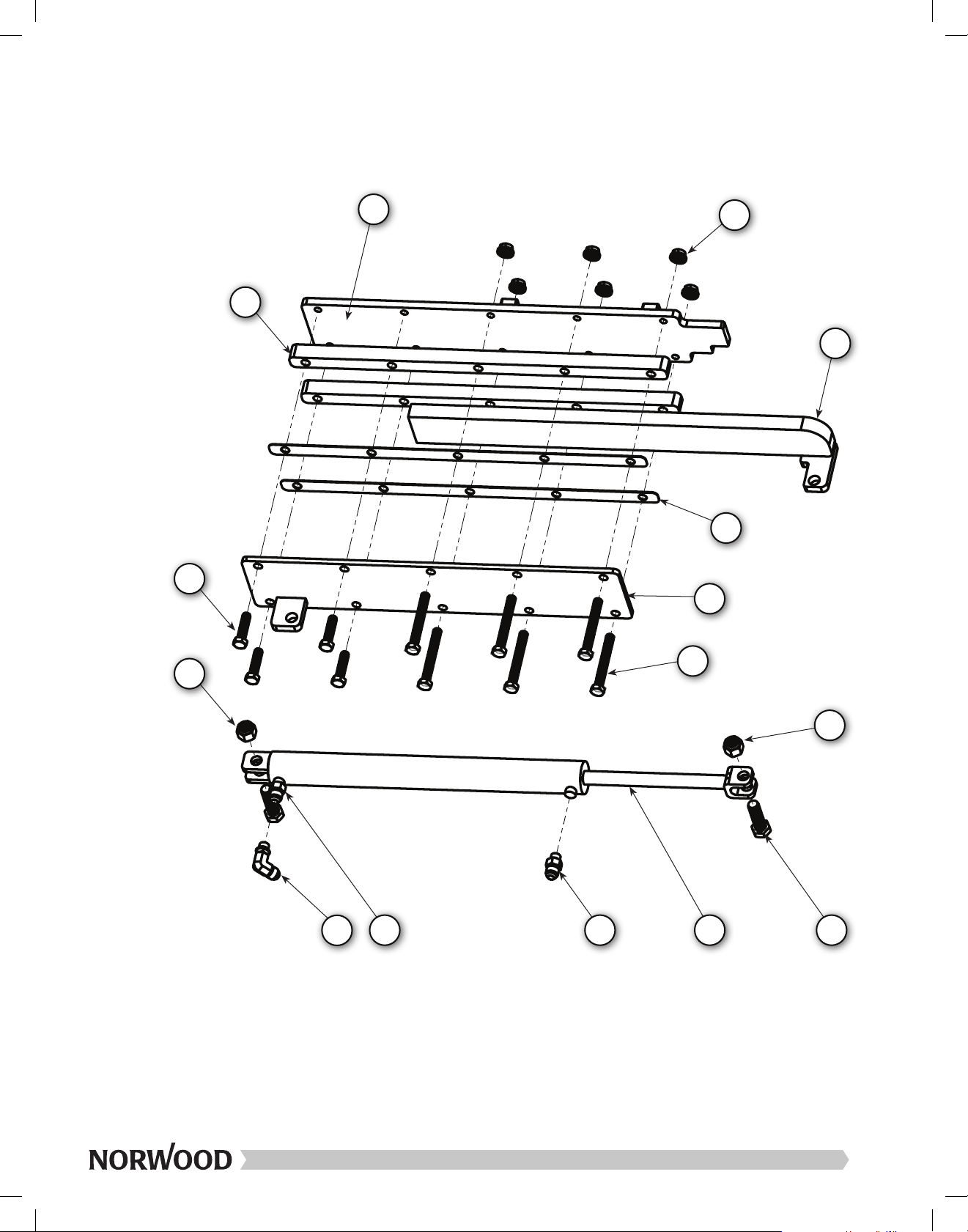
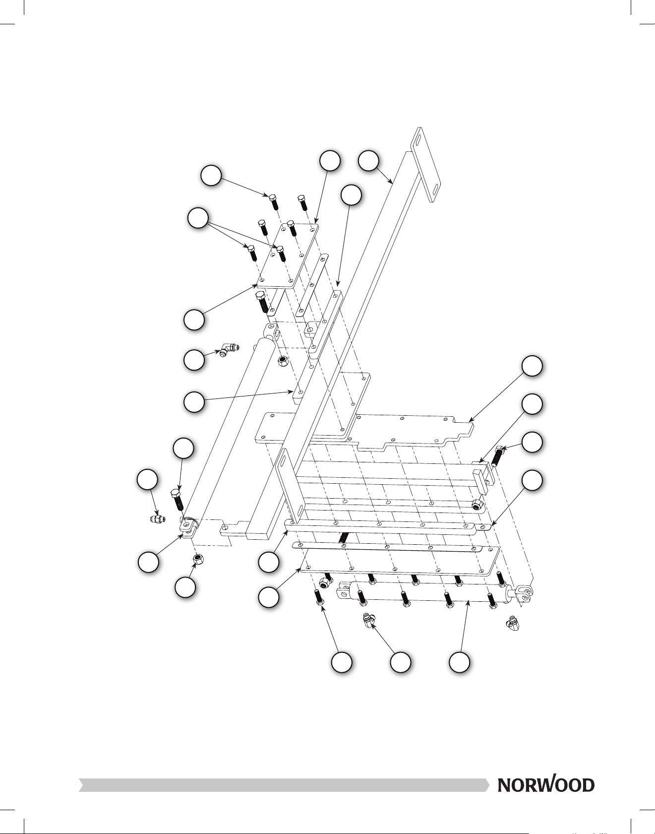
EN–4
Box Contents and Parts List
Item Qty. Description Norwood No.
LM34-HD-LC #1 (Hydraulic Log Clamping Box #1)
25 2 Hydraulic hose - Valve to horizontal clamp cylinder NOR006-0009
Dog Bar Assembly #1 (factory-assembled):
1 1 1/2 nut - nylon lock nut FASN-12NLN
2 1 1/2 x 1 3/4" bolt - hex bolt FASB-12134H
28 1 Hydraulic log dog - Bar LM34-H-LD-0008
Dog Bar Assembly #2 (factory-assembled):
1 1 1/2 nut - nylon lock nut FASN-12NLN
2 1 1/2 x 1 3/4" bolt - hex bolt FASB-12134H
12 1 Hydraulic cylinder (20” stroke, 1-1/8” bore, 1/2” pin holes, retracted length 25.3 CYL-20-118-25.3
30 1 Hydraulic log dog - Cylinder slider mount bracket LM34-H-LD-0020
LM34-HD-LC #2 (Hydraulic Log Clamping Box #2)
26 2 Hydraulic hose - Valve to vertical clamp cylinder NOR006-0010
Vertical Dog Assembly (factory-assembled):
1 2 1/2 nut - nylon lock nut FASN-12NLN
2 2 1/2 x 1 3/4" bolt - hex bolt FASB-12134H
4 14 3/8 x 1 1/2" bolt - regular hex bolt FASB-38112
5 2 3/8 x 1 1/4" bolt - regular hex bolt FASB-3814H
11 1 Hydraulic cylinder (12" stroke, 1-1/8" bore, 1/2" pin holes, retracted length 17.3 CYL-12-118-17.3
27 1 Hydraulic log dog - Back plate LM34-H-LD-0018
29 1 Hydraulic log dog - Clamp LM34-H-LD-0007
31 1 Hydraulic log dog - Front plate - Horizontal LM34-H-LD-0014
38 1 Hydraulic log rest - Front plate LM34-H-LR-0101
33 2 Hydraulic log dog - Shim - Horizontal LM34-H-LD-0021
40 2 Hydraulic log rest - Shim LM34-H-LR-0113
35 1 Hydraulic log dog - Spacer - Horizontal LM34-H-LD-0015
41 2 Hydraulic log rest - Spacer - Vertical LM34-H-LR-0106
LM34-HD-LC #3 (Hydraulic Log Clamping Box #3)
23 1 Hydraulic hose - Valve to "T" NOR006-0003
24 1 Hydraulic hose - Valve to flow divider NOR006-0006
Log Rest Assembly (factory-assembled):
1 2 1/2 nut - nylon lock nut FASN-12NLN
2 2 1/2 x 1 3/4" bolt - hex bolt FASB-12134H
4 4 3/8 x 1 1/2" bolt - regular hex bolt FASB-38112
9 6 3/8 x 3" bolt - full thread hex bolt FASB-38X3FTH
11 1 Hydraulic cylinder (12” stroke, 1-1/8” bore, 1/2” pin holes, retracted length 17.3 CYL-12-118-17.3
37 1 Hydraulic log rest - Back plate LM34-H-LR-0103
38 1 Hydraulic log rest - Front plate LM34-H-LR-0101
39 1 Hydraulic log rest - Log post LM34-H-LR-0102
40 2 Hydraulic log rest - Shim LM34-H-LR-0113
41 2 Hydraulic log rest - Spacer - Vertical LM34-H-LR-0106

Item Qty. Description Norwood No.
LM34 Bag: Hydraulic Log Clamping Bag (LM34 BAG: HD-LC-BAG #1)
3 12 3/8 nut - flanged (regular) FASN-38RFL
13 1 Hydraulic fitting - "T" 3/8 MJ X 3/8 MJ X 3/8 MJ LM34-H-FT-01
14 1 Hydraulic fitting - #8 SAE plug LM34-H-FT-04
15 3 Hydraulic fitting - 3/8 MJ X #4 SAE male LM34-H-FT-07
16 5 Hydraulic fitting - 3/8 MJ X #4 SAE male, 90 degrees LM34-H-FT-08
17 3 Hydraulic fitting - 3/8 MJ X #8 SAE male LM34-H-FT-10
18 1 Hydraulic flow divider/combiner - 50:50, 1/2" SAE ports HYD-FLODIV
— 1 Instructions - Hydraulic Log Clamping System LM34-HD-41600-INST
43 1 Hydraulic flow divider/combiner - 6-12GPM 3500 PSI HYD-FLOBODY
LM34-HD-LC #4 (Hydraulic Log Clamping Box #4)
20 2 Hydraulic hose - "T" to rear log rest retract NOR006-0005
21 1 Hydraulic hose - Flow divider to front log rest extend NOR006-0007
22 1 Hydraulic hose - Flow divider to rear log rest extend NOR006-0008
Log Rest Assembly (factory-assembled):
1 2 1/2 nut - nylon lock nut FASN-12NLN
2 2 1/2 x 1 3/4" bolt - hex bolt FASB-12134H
4 4 3/8 x 1 1/2" bolt - regular hex bolt FASB-38112
9 6 3/8 x 3" bolt - full thread hex bolt FASB-38X3FTH
11 1 Hydraulic cylinder (12” stroke, 1-1/8” bore, 1/2” pin holes, retracted length 17.3 CYL-12-118-17.3
37 1 Hydraulic log rest - Back plate LM34-H-LR-0103
38 1 Hydraulic log rest - Front plate LM34-H-LR-0101
39 1 Hydraulic log rest - Log post LM34-H-LR-0102
40 2 Hydraulic log rest - Shim LM34-H-LR-0113
41 2 Hydraulic log rest - Spacer - Vertical LM34-H-LR-0106
EN–5

Install the log rest assembly to the cross
bunk, using the 3/8” nut (item #3). See
illustration for location.
NOTE:
The Log Loader mounting
bracket should be installed at
this time using 3/8" x 2 1/2"
bolt (Item 5). (If purchased.)
NOTE:
The log rests and the log dog can be positioned
at your convenience. The locations shown in this
page are just a recommendation for an average
size log.
Step 11:
Install log dog at hole #18 & 19.
Hole #1
EN–6
Installation: Log Rest
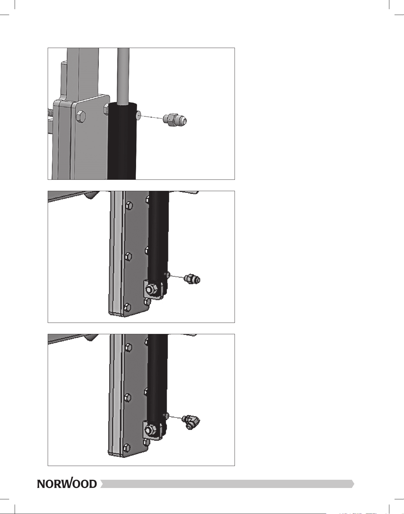
Install the 3/8 MJ x #4 SAE male 90
degrees hydraulic fitting (item #16) to the
log rest cylinder bottom port (item #11)
located at the back of the sawmill.
Install the 3/8 MJ x #4 SAE male
hydraulic fitting (item #15) to the log rest
cylinder bottom port (item #11) located at
the front of the sawmill.
Install the 3/8 MJ x #4 SAE male,
hydraulic fitting (item #15) to the log rest
cylinders top port (item #11).
EN–7
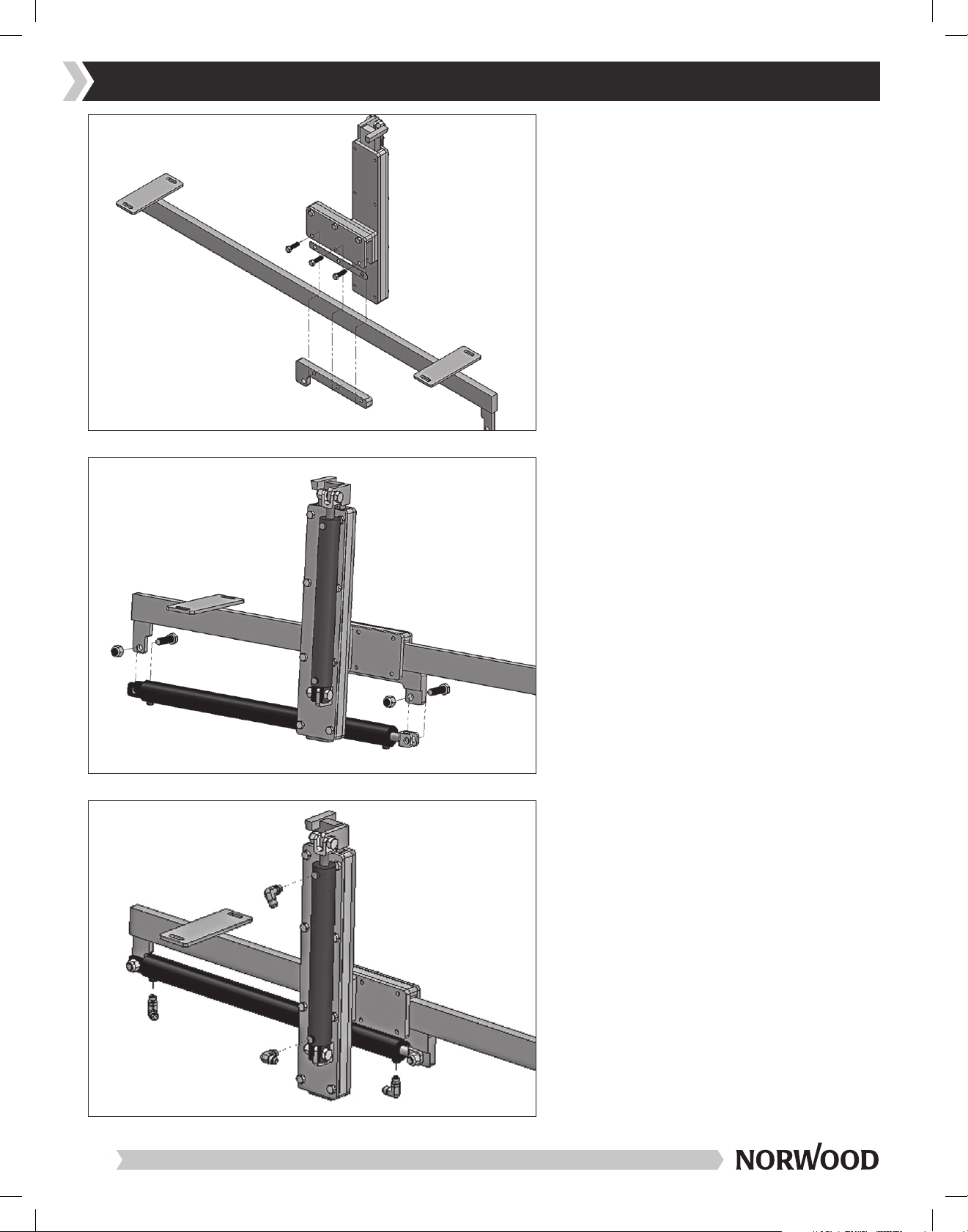
Install the 3/8 MJ x #4 SAE male 90
degrees hydraulic fittings (item #16).
(four places)
Install the hydraulic cylinder (item #12)
onto the log dog bar (item #28) using
the 1/2” x 1 3/4” bolts (item #2) and nuts
(item #1). See left picture for cylinder
orientation.
Assemble the factory assembled
hydraulic clamp sub-assembly with
the horizontal shim (item #33) and the
cylinder slider mount bracket (item #30)
using the 3/8” x 1 1/2” bolts (item #4).
Note: Do not forget the shims (item #33).
EN–8
Installation: Log Clamp
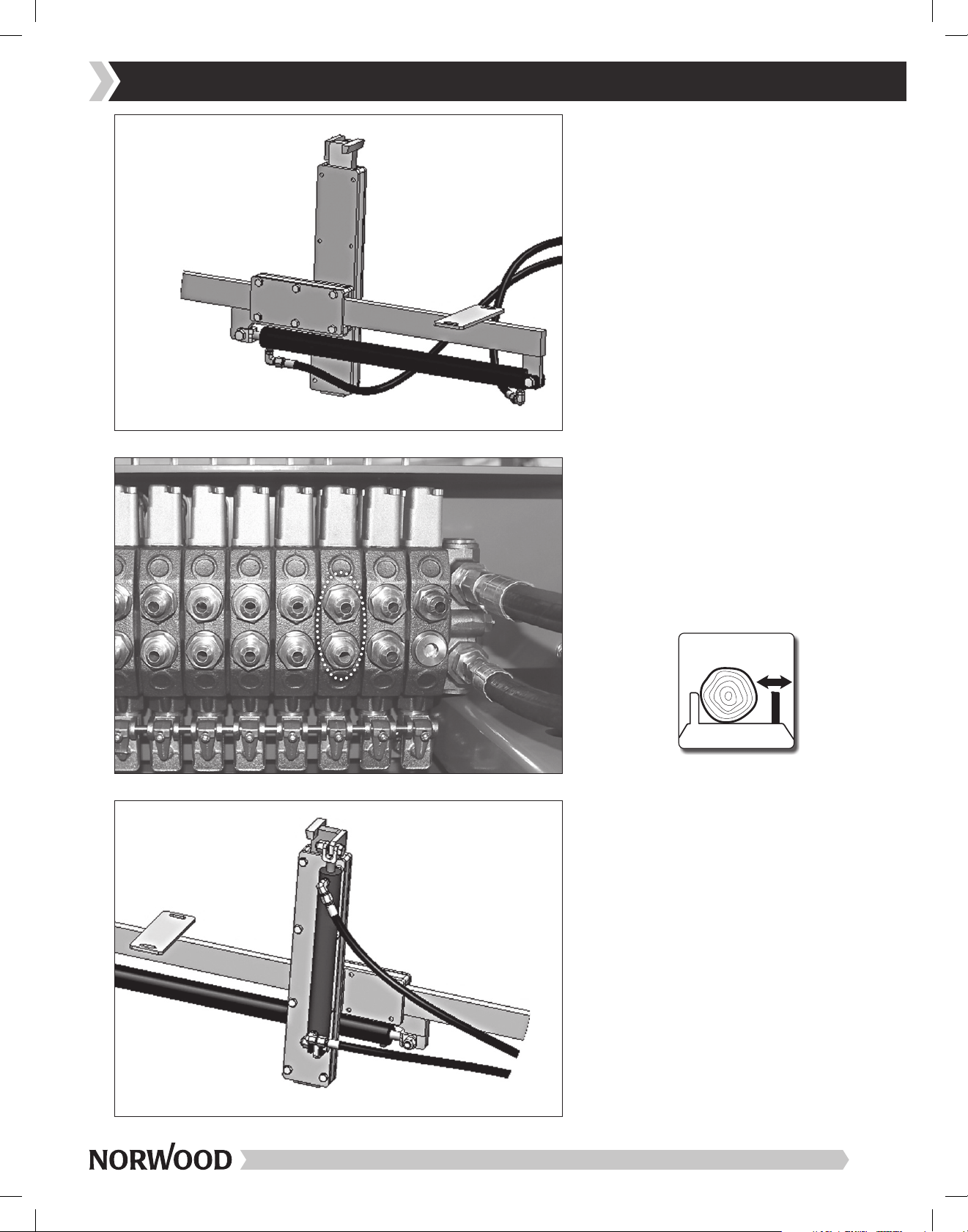
Connect the 136” horizontal log clamp
hoses (item #25 labeled NOR006-0009)
to the horizontal cylinder (item #12).
Connect the log clamp hoses (item
#25 labeled NOR006-0009) from the
horizontal cylinder to the hydraulic valve
section.
Note: Connect the cylinder retraction
hose to the bottom valve section port.
Connect the 140” vertical log clamp
hoses (item #26 labeled NOR006-0010)
to the vertical cylinder (item #11).
EN–9
Installation: Log Clamp Hoses
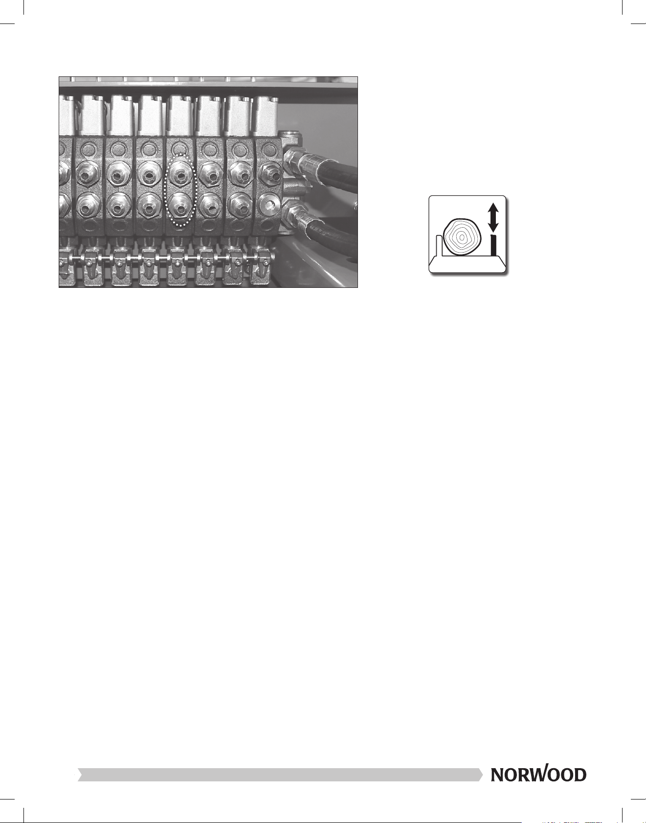
Connect the log clamp hoses (item #26
labeled NOR006-0010) from the vertical
cylinder to the hydraulic valve section.
Note: Connect the cylinder retraction
hose to the bottom valve section port.
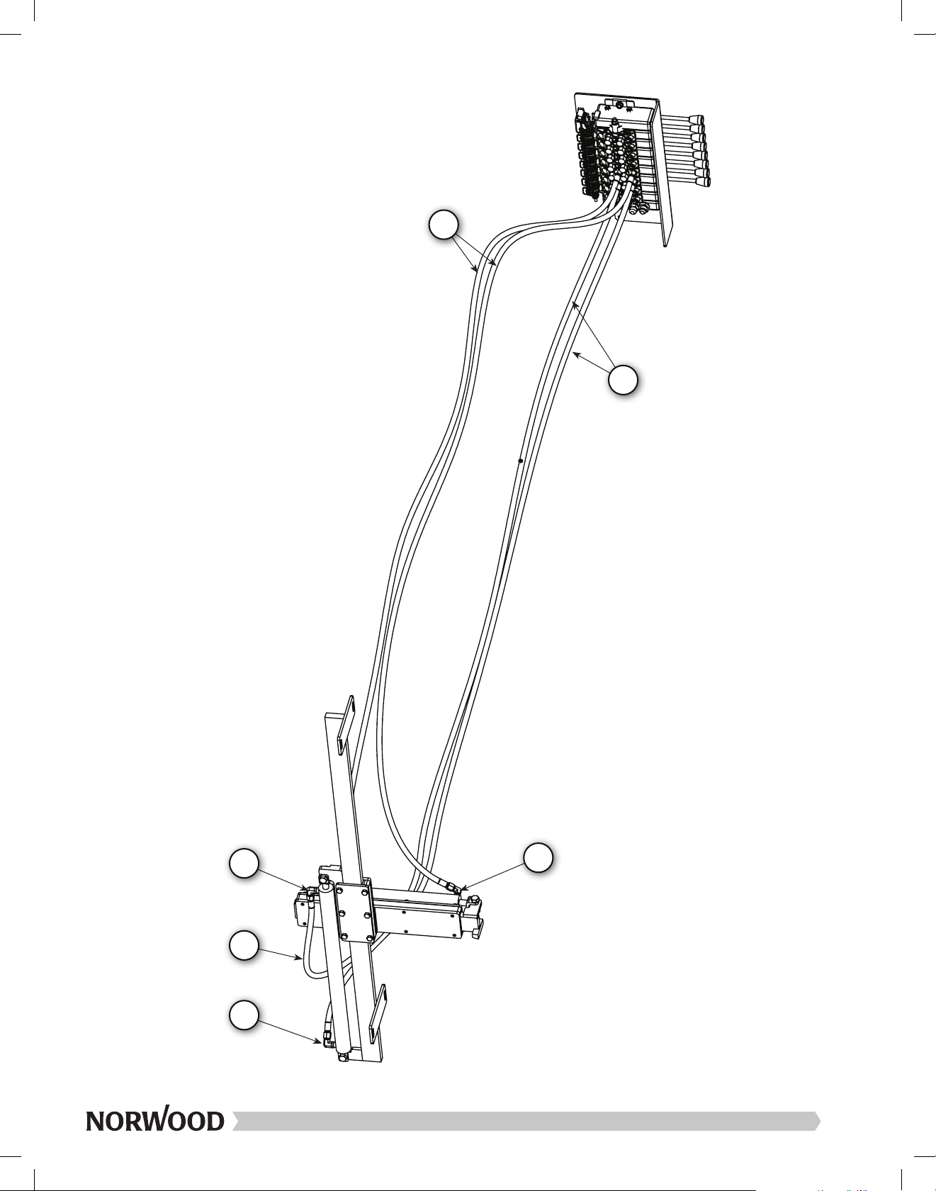
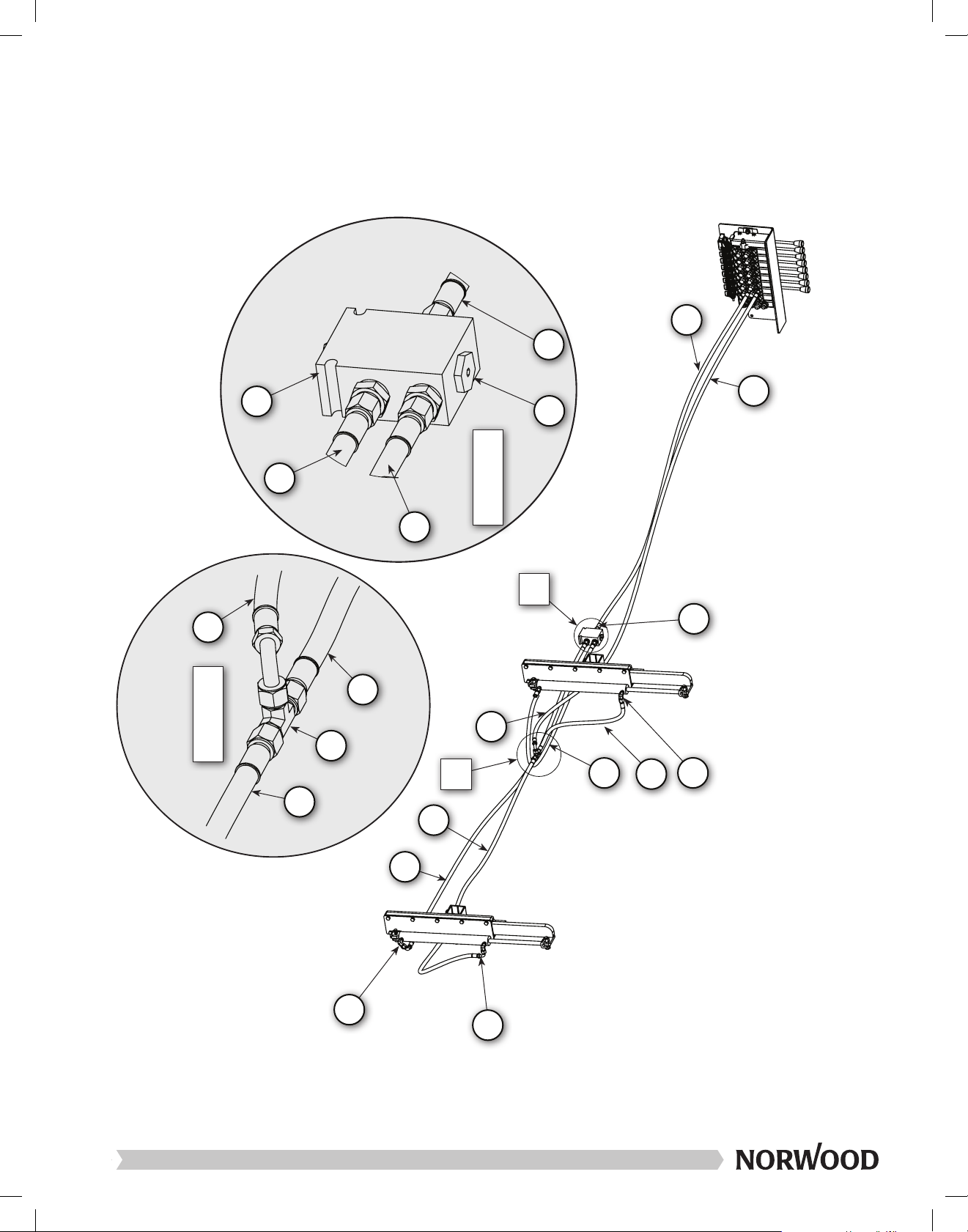
EN–10

Connect the 48” hydraulic log rest hose
(item #21 labeled NOR006-0007) to the
flow divider (item #18), as shown in the
picture.
Then, connect the other end of the log
rest hose (item #24 labeled NOR006-
0006) to the hydraulic flow divider (item
#18), as shown in the picture.
Connect the 91” log rest hose (item #24
labeled NOR006-0006) to the correct
valve section (bottom port).
EN–11
Installation: Log Rest Hoses

Then, connect the other end of the log
rest hose (item #22 labeled NOR006-
0008) to the bottom port of the rear rest
hydraulic cylinder (item #11), located at
the back of the sawmill.
Connect the 93” hydraulic log rest hose
(item #22 labeled NOR006-0008) to the
flow divider (item #18), as shown in the
picture.
Then, connect the other end of the log
rest hose (item #21 labeled NOR006-
0007) to the bottom port of the log rest
hydraulic cylinder (item #11), located at
the front of the sawmill.
EN–12
Other manuals for LumberMax HD38
5
This manual suits for next models
3
Table of contents
Languages:
Popular Power Tools manuals by other brands


Metabo
Metabo SSW 650 operating instructions

Pladdet
Pladdet PSS230 Operation and maintenance manual

Milwaukee
Milwaukee 0881-20 Operator's manual

Virutex
Virutex AG98E operating instructions

Parkside
Parkside PAMFW 20-LI A1 Translation of the original instructions

Milwaukee
Milwaukee C12 MT-0 Original instructions


