norxe P1 User manual
P1 User Guide
norxe

© All Rights Reserved
www.norxe.com
P1 User Guide
Page 2 of 40
Norxe AS
Dokka 3B
1671 Fredrikstad
Norway
Document Revision Number: V1.04 - EN USA
Printed in Norway March 2018

© All Rights Reserved
www.norxe.com
P1 User Guide
Page 3 of 40
Table of Contents
1 Introduction......................................................................................................................................................... 5
1.1 Thank you................................................................................................................................................... 5
1.2 Features...................................................................................................................................................... 5
1.3 About this User Guide................................................................................................................................ 5
2 Copyright © and Legal Information .................................................................................................................... 6
3 Changes ............................................................................................................................................................... 6
4 Warranty.............................................................................................................................................................. 6
5 Safety and General Information.......................................................................................................................... 7
5.1 Safety.......................................................................................................................................................... 7
5.2 Warnings .................................................................................................................................................... 7
6 Service ................................................................................................................................................................. 8
6.1 Federal Communications Commission (FCC) ............................................................................................. 8
6.2 Disposal ...................................................................................................................................................... 8
7 Packaging............................................................................................................................................................. 9
7.1 What is in the Box ...................................................................................................................................... 9
7.2 Unpacking................................................................................................................................................. 10
7.3 Inspection................................................................................................................................................. 10
8 Getting to know the projector........................................................................................................................... 11
8.1 Projector chassis ...................................................................................................................................... 11
8.2 Projector Keypad...................................................................................................................................... 12
8.3 Remote Control........................................................................................................................................ 13
8.5 Connectivity ............................................................................................................................................. 14
8.7 User Interface........................................................................................................................................... 15
8.8 Menu System ........................................................................................................................................... 15
8.9 Menu Navigation...................................................................................................................................... 15
8.10 Main Menu .......................................................................................................................................... 16
8.10.1 Picture Menu ........................................................................................................................... 16
8.10.2 Source Menu............................................................................................................................ 19
8.10.3 Install Menu............................................................................................................................. 19
8.10.4 Status Menu............................................................................................................................. 21
8.10.5 Night Vision Menu ................................................................................................................... 22
8.10.6 3D Settings Menu .................................................................................................................... 22
8.11 Lens Options ........................................................................................................................................ 23
9 Basic Setup & Installation.................................................................................................................................. 24
9.1 Ventilation................................................................................................................................................ 24
9.2 Orientation............................................................................................................................................... 24
9.3 Mounting.................................................................................................................................................. 25

© All Rights Reserved
www.norxe.com
P1 User Guide
Page 4 of 40
9.4 Accessory Interface Fixing Points............................................................................................................. 26
9.5 Lens Mounting.......................................................................................................................................... 26
9.6 Locking Zoom & Focus.............................................................................................................................. 27
9.7 Lens Support ............................................................................................................................................ 27
9.8 Lens Adjustment....................................................................................................................................... 28
9.9 Scheimpflug Adjustment.......................................................................................................................... 28
10 Advanced Setup & Installation................................................................................................................. 29
10.1 Dual Head Mode.................................................................................................................................. 29
10.1.1 RGB + Separate IR Input........................................................................................................... 29
10.1.2 Top/Bottom Input.................................................................................................................... 30
10.1.3 3D (Active) Input...................................................................................................................... 31
11 Maintenance ............................................................................................................................................ 33
11.1 Safety ................................................................................................................................................... 33
11.2 Cleaning ............................................................................................................................................... 33
11.3 Calibration ........................................................................................................................................... 33
11.4 Software Updates ................................................................................................................................ 33
12 Technical Data.......................................................................................................................................... 34
12.1 Mechanical........................................................................................................................................... 34
12.2 Packaging............................................................................................................................................. 35
12.3 Electrical .............................................................................................................................................. 35
12.4 Connectivity......................................................................................................................................... 35
12.5 Optical.................................................................................................................................................. 36
12.6 Audible noise ....................................................................................................................................... 36
13 Environmental Conditions........................................................................................................................ 37
13.1 Operating............................................................................................................................................. 37
13.2 Non-Operating..................................................................................................................................... 37
13.3 Storage & Transport ............................................................................................................................ 37
13.4 Environmental Standards .................................................................................................................... 38
13.5 MTBF.................................................................................................................................................... 38
13.6 Safety Approvals.................................................................................................................................. 38
13.7 Radio Interference Approvals.............................................................................................................. 38
14 Technical Data, Projection Lenses............................................................................................................ 39
14.1 N1......................................................................................................................................................... 39
14.2 N2......................................................................................................................................................... 39

© All Rights Reserved
www.norxe.com
P1 User Guide
Page 5 of 40
1Introduction
1.1 Thank you
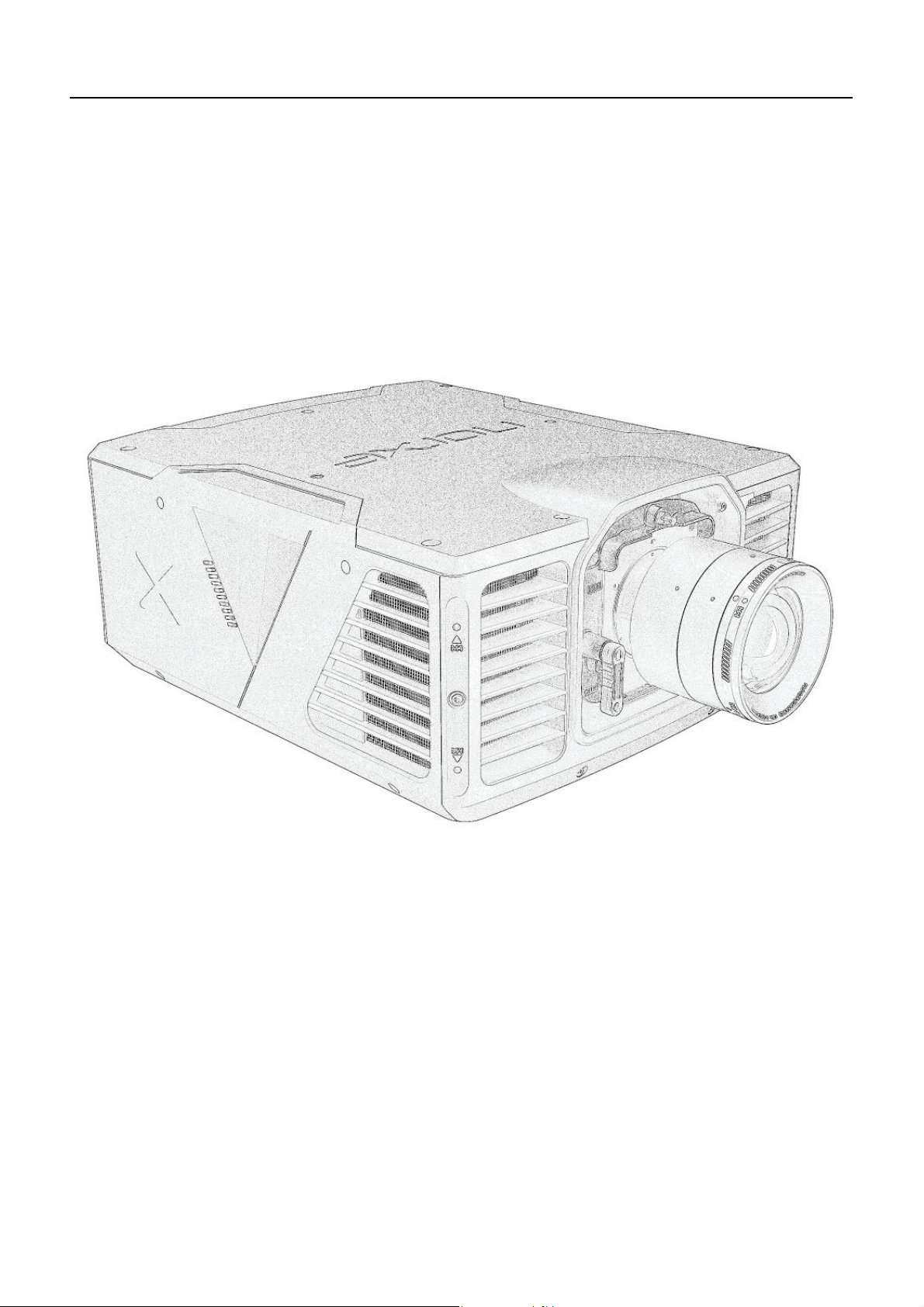
Thank you for purchasing this projector.
The projector combines high resolution DLP® and next generation LED technology to provide best in class image
quality. Future proofed interchangeable lens options comprise all glass, aspherical, no doublet elements. High
quality components ensure long life and low maintenance. The chassis footprint is compact and rugged, it is
ideally suited to the most demanding applications including multi-channel and motion. The projector is supplied
with a 5-year manufacturer’s limited warranty.
1.2 Features
•Single chip DLP® technology.
•WQXGA (2560 x 1600) / WUXGA (1920 x 1200) resolution, depending on variant.
•High brightness.
•High contrast.
•High dynamic range.
•Next generation LED light sources.
•Optional NVG capable - Default IR LED wavelength is 740nm, other wavelengths available.
•Ideally suited to demanding applications such as multi-channel and motion.
•Lens options comprise all glass, aspherical, no doublet optical elements & include ‘lens lock’
technology. The ‘lens lock’ feature allows the end user to physically lock the lens to the projector
body, lock the lens adjustment rings into position and lock the lens body to 3rd party supporting
clamps for additional rigidity in extreme circumstances.
•Lens focus, zoom (where applicable) & Iris on all lens options is motorized. Stepper motors are used
throughout to ensure high degree positional accuracy.
•Scheimpflug adjustment is a standard feature.
•Designed for easy installation - central lens position, multiple fixing points, accessory fixing points.
•Orientation free installation.
•Compact and rugged.
•High quality components ensure long life and low maintenance.
•50,000-hour service interval.
•5-year manufacturer’s limited warranty.
1.3 About this User Guide
All users of this product are strongly recommended to read this User Guide prior to setting up and using the
projector for the first time. That it is stored safely after use for future reference as appropriate.
All units of measurement and weight provided in this User Guide are according to the International Standard of
Units (SI units).
Illustrations are provided for reference only and may differ from your actual product.

© All Rights Reserved
www.norxe.com
P1 User Guide
Page 6 of 40
2Copyright © and Legal Information
All rights reserved. Content may not be copied or reproduced without the prior written consent of the owner.
No liability is assumed for loss or damage, be it direct or indirect, resulting from the use of its products or from
the use of information contained within this document.
Many factors influence the performance of an installation, including but not limited to the image sources,
projection screens, cabling, environmental conditions etc. It is the responsibility of the system integrator to
make sure all these factors are correct and within specification.
Every effort has been made to ensure that the information contained in this document is accurate. However, no
liabilities are assumed for any errors that may appear within this document.
Company names, brands and product names mentioned in this document may be trademarks or registered
trademarks of their respective companies, protected by international law.
3Changes
The specifications and functionality of products and documentation may be changed from time to time, without
prior notice, to improve performance.
4Warranty
For product warranty terms and conditions please refer to the manufacturer’s Warranty Statement which is
available separately.

© All Rights Reserved
www.norxe.com
P1 User Guide
Page 7 of 40
5Safety and General Information
5.1 Safety
•This projector complies with safety regulations for Information Technology Equipment intended to
operate in a normal (office-like) environment. Please read the safety instructions before set-up and
operation.
•Use only the supplied, grounded power cord or an approved replacement power cord. Unplug the
projector if it is not used over an extended period.
•Always operate the projector within the stated voltage, humidity and temperature specifications.
OPERATION OUTSIDE THE SPECIFIED LIMITS MAY AND PROBABLY WILL DAMAGE THE UNIT!
•To reduce the risk of electrical shock and fire, do not expose the projector to moisture or rain.
•Never expose the projector to smoke, dust, sand or other fine particles, oil or chemicals.
•To avoid overheating, install the projector properly to allow for free air-flow. Observe the minimum
distance to a solid object guidance described within this User Guide. Make sure the ambient
temperature is within specified limits to reduce fan noise and ensure long life. Cool air intakes are on the
front and the on the sides to the front, while warm air is exhausted to the rear. NEVER COVER THE
VENTILATION SLOTS!
•DO NOT STARE INTO THE LIGHT BEAM! Strong light is emitted from the projection lens and staring into
the light beam may cause eye-damage.
•NEVER OPEN THE PROJECTOR! The unit contains no user-serviceable parts. Refer all service to qualified
personnel only.
5.2 Warnings
•When installing in table mount orientation make sure that the projector is positioned on a suitable flat,
correctly rated load bearing surface. When not in table mount orientation make sure that the projector
is properly fastened and secured to an approved mount using the mounting interface points provided
(underside of projector).
•Regularly clean the ventilation slots (inlet and exhaust) with a vacuum cleaner to ensure optimal cooling
and lowest fan noise is always maintained.
•Make sure no objects enter the ventilation openings of the projector.
•Remove the lens cap before turning on the projector. The lens cap may melt and damage the lens if it is
not removed before use.
•Only connect the projector to specified signal sources. Connecting to other sources may result in
distorted images and malfunction.
•Do not drop the projector.

© All Rights Reserved
www.norxe.com
P1 User Guide
Page 8 of 40
6Service
This product does not contain end user serviceable parts. If it fails to function as expected carefully check that
the lens is properly inserted. That video inputs are correctly inserted and configured. That the power cord is
properly connected, that the facility main circuit breaker is intact.
If the problem persists, please contact your reseller or an authorised service center for assistance. Please
provide product details including Part Number and Serial Number plus a brief description of the fault.
WARNING! The projector contains a CR2032 battery. RISK OF EXPLOSION IF THE BATTERY IS REPLACED BY
AN INCORRECT TYPE. Dispose of used battery properly as described below.
6.1 Federal Communications Commission (FCC)
NOTE! This equipment has been tested and found to comply with the limits for a Class A digital device,
pursuant to part 15 of the FCC Rules. These limits are designed to provide reasonable protection against
harmful interference when the equipment is operated in a commercial environment. This equipment
generates, uses, and can radiate radio frequency energy and, if not installed and used in accordance with
the instruction manual, may cause harmful interference to radio communications. Operation of this
equipment in a residential area is likely to cause harmful interference in which case the user will be
required to correct the interference at his own expense.
6.2 Disposal
•Please dispose-of this projector at end-of-life to a proper recycling facility.
This product conforms to all requirements of the WEEE (Waste Electrical and Electronic Equipment) EU
directive. The projector shall be recycled properly and can be dis-assembled for proper recycling of the
individual components.
This product conforms to all requirements in the RoHS (Reduction of Harmful Substances) EU directive.
The projector does not contain lead or mercury.

© All Rights Reserved
www.norxe.com
P1 User Guide
Page 9 of 40
7Packaging
7.1 What is in the Box
The projector and the projection lens are shipped separately, in separate boxes. This is because the choice of
projection lens can vary with each application.
Projector box:
•Projector body.
•Power cord (plug type will vary depending upon shipping destination).
•Remote Control (including batteries).
•Lens fixings. Comprising: -
•4 x DIN 912 M6 x 8 mm Allen Socket Bolts. A 5mm Allen Key is required for fitment / adjustment
(not supplied). These fixings can be used to mechanically affix the projection lens to the projector
body. Use is recommended. This is especially relevant to motion-based applications.
•2 x DIN 916 M3 x 3 mm Allen Socket Studs. 1.5 mm Allen Key required for fitment / adjustment (not
supplied). These fixings can be used to mechanically lock the projection lens focus and zoom rings
into position after installation. Use is at the customer’s discretion.
•Quick Start Guide.
Projector body Remote control Power cord Projection Quick
lens fixings Start Guide
(lens body, focus & zoom)
Lens box:
•Projection lens.
Projection lens
(in separate box)

© All Rights Reserved
www.norxe.com
P1 User Guide
Page 10 of 40
7.2 Unpacking
Carefully remove the sealing tape from the packing box and open. Remove the protective foam inserts and
remove the projector / projection lens.
NOTE! Please retain all packaging. Should you need to return your product for repair and / or for service
at any time in the future items should be returned in original packaging where possible.
7.3 Inspection
As soon as the projector / projection lens is unpacked inspect it for transit induced damage. The projector /
projection lens left the factory in perfect condition. If damage is evident after unpacking, please contact the
carrier and report it immediately.
© All Rights Reserved
www.norxe.com
P1 User Guide
Page 11 of 40
8Getting to know the projector
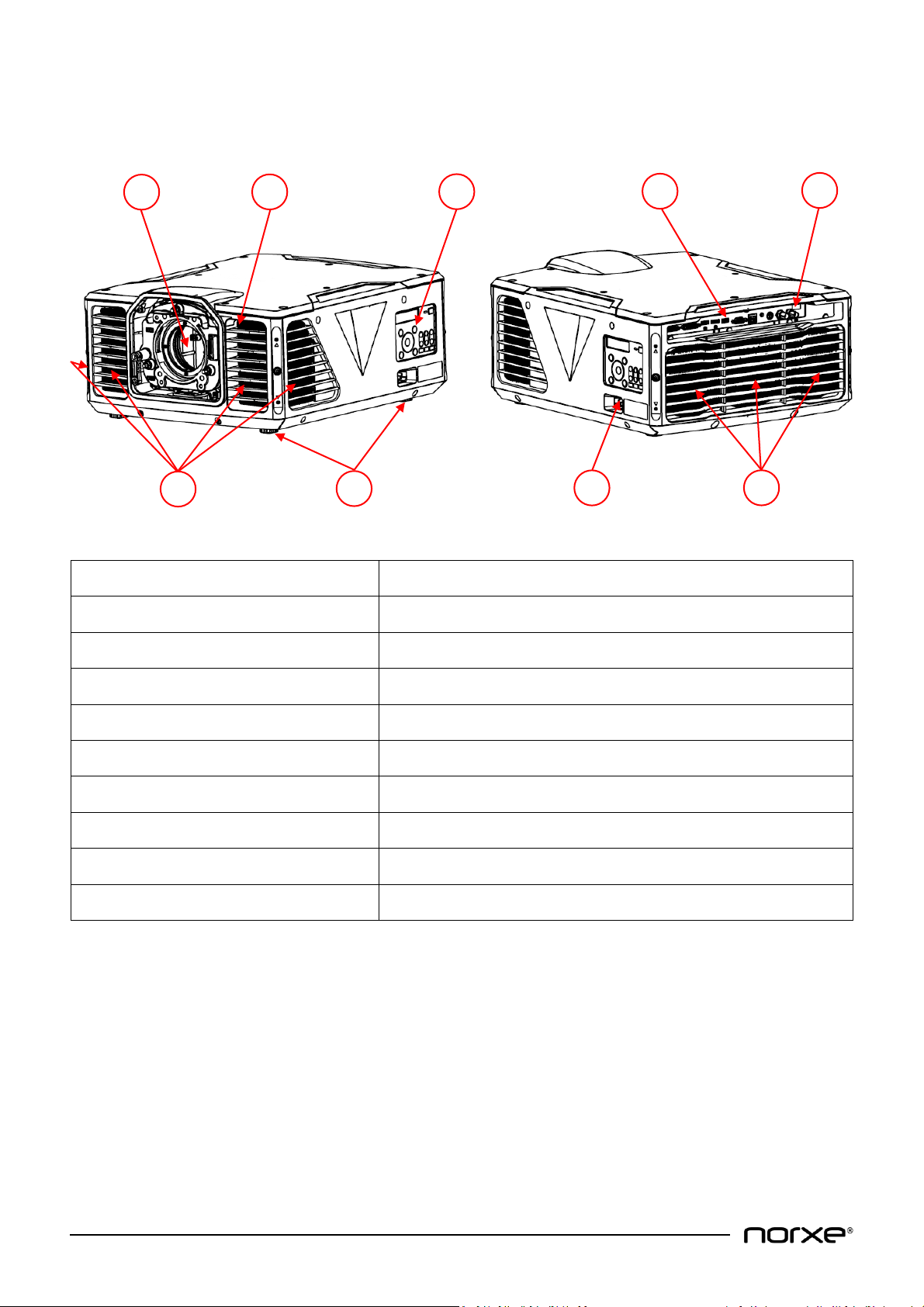
8.1 Projector chassis
Item Number
Description
1
Projector Lens Holder with lens-lid
2
IR Receiver Front
3
Keypad & LCD
4
Video & I/O Connections
5
IR Receiver Rear
6
Air Intakes (front & front sides)
7
Adjustable Feet (Qty 4) - 1 per corner
8
Mains Power Inlet Connector
9
Projector Air Exhaust
A range of interchangeable lens options is available separately. Specifying the correct lens for the intended
application is the responsibility of the purchaser.
1
2
3
5
4
6
8
7
9
© All Rights Reserved
www.norxe.com
P1 User Guide
Page 12 of 40
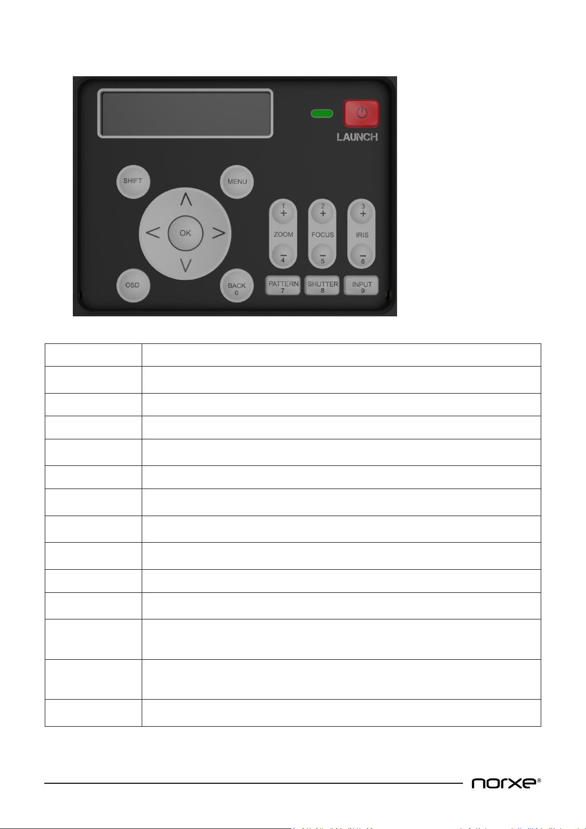
8.2 Projector Keypad
Key
Description
SHIFT
Press to activate the lens shift mechanism. Use the arrow keys to adjust lens shift
vertically or horizontally.
MENU
Press to enable or disable the on-screen menu system.
LAUNCH
Toggles power on and off (press twice for off as per on-screen prompt).
Arrow keys
Use to move lens shift up / down / left / right and to navigate the on-screen menu
system.
OK
Press to select on-screen display sub-menu.
ZOOM
Press + or - to adjust zoom in or out. Provides additional numeric functionality for
values 1 and 4.
FOCUS
Press + or - to adjust lens focus in or out. Provides additional numeric functionality for
values 2 and 5.
IRIS
Press + or - to open or close the lens iris. Provides additional numeric functionality for
values 3 and 6.
OSD
Toggles the OSD (On Screen Display) on and off.
BACK
Press to move back in the menu system. Provides additional numeric functionality for
value 0.
PATTERN
Press to display test pattern image. Pressing repeatedly cycles through a set of
preconfigured embedded test patterns. Provides additional numeric functionality for
value 7.
SHUTTER
Toggles the illumination system on and off to give a black image (while the LAUNCH key
above controls the power to the projector itself). Provides additional numeric
functionality for value 8.
INPUT
Press to sequence between the source inputs. Provides additional numeric functionality
for value 9.

© All Rights Reserved
www.norxe.com
P1 User Guide
Page 13 of 40
8.3 Remote Control
The projector is supplied with a Remote Control. The Remote Control can be used in infrared (IR) mode or in
wired mode. A wired lead with 3.5 mm Jack terminations is required for the latter mode of operation (wired lead
not supplied as standard).
Remote Control functionality mirrors that of the projector keypad.
8.4 Status Indicator Light Modes of Operation
The Status Indicator Light and LCD are integral to the projector Keypad. They are both positioned adjacent to the
LAUNCH (power on / off) button. The status indicator light is used to display projector status, the LCD is used to
display related additional information in certain circumstances.
Status Indicator Light Modes of Operation
-PERMANENT AMBER LIGHT: The projector light source is off. The projector is in standby / ready mode.
-PERMANENT GREEN LIGHT: The projector light source is on. The projector is active.
-PERMANENT RED LIGHT: Over temperature. Projector shut down (to standby).
-FLASHING AMBER LIGHT: The projector is in a transitional state between standby and active or alternatively
between active and standby.
-FLASHING RED LIGHT: Critical error and / or one or more cooling fans not working properly.
NOTE! - Critical error cause dependent the projector may shut down (to standby) and restart. It is
normal for the Status Indicator to flash red during this process.
NOTE! - Projector will shut down if over temperature.
LCD Modes of Operation
-‘Warming up …’ Additional information message displayed in conjunction with flashing yellow status
indicator light.
-‘Shutting down …’ Additional information message displayed in conjunction with flashing yellow status
indicator light. Message is displayed for approximately 2 minutes. The projector light source cannot be
restarted during this timeframe.

© All Rights Reserved
www.norxe.com
P1 User Guide
Page 14 of 40
8.5 Connectivity
Item Number
Description
1
Dual Link DVI Input 1 Connector
2
Dual Link DVI Input 2 Connector
3
HDMI 2.0 Input Connector
4
DisplayPort 1.2 Input Connector
5
RJ45 LAN Connector
6
USB 2.0 Connector (with nominal 5V / 1.5A output)
7
RS232 DB9 Connector
8
RC (Remote Control, 1.5 mm Mini Jack) Connector
9
Sync 1 (Mini DIN with nominal 5V output) Output Connector
10
Sync 2 (BNC) Input Connector
11
Sync 3 (BNC) Output Connector
8.6 Power
Use only the supplied, grounded power cord or an approved replacement power cord. Unplug the projector if it
is not used over an extended period.
1
2
3
4
6
8
10
5
7
9
11
© All Rights Reserved
www.norxe.com
P1 User Guide
Page 15 of 40
8.7 User Interface
It is possible to control the projector using the remote control, via either wired or wireless LAN, or via the
projector keypad.
The projector can also be controlled using a PC-application, available separately, using ASCII commands over
TCP/IP. You will need to download, install and run this application on a compatible computer that is on the same
network as the projector(s). For more information about the application, please check the manufacturers
website or contact your dealer.
8.8 Menu System
The Menu system gives access to core projector controls and settings via an on-screen Display.
NOTE! Menu functionality may vary slightly from the illustrations / descriptions below depending on
projector variant and product software version.
8.9 Menu Navigation
The menu is organized hierarchically. Options appear according to user selection.
Pressing the Menu button toggles the menu on and off. Navigate the menu using the arrow keys (left, right, up,
down) and the OK and Back buttons. Select the desired option using the arrow keys, press OK to select. In some
instances, numeric input is required. Press Back to step up in the hierarchy.
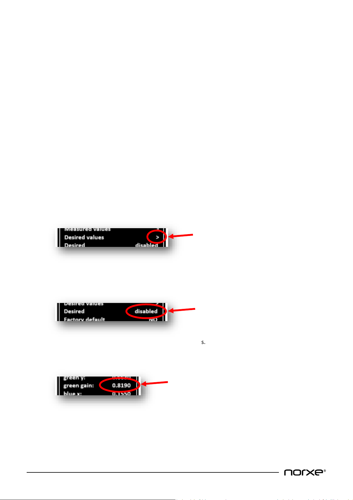
Sub-menus are indicated with an arrow to the right (>) like this:
Press the OK button to navigate to the underlying sub-menu.
Selected (or default) options are shown where there is no further sub-menu like this:
Push the arrow keys left or right to select between the alternatives.
Numbers are shown like this:
Use the number keys on the remote control or the projector keypad to change values.

© All Rights Reserved
www.norxe.com
P1 User Guide
Page 16 of 40
8.10 Main Menu
The main menu on-screen display provides a gateway to the sub menu system.
›
Picture allows access to colorimetry and brightness parameters in many ways, both individual color
control as well as common controls.
Source controls which video signal source is active. Source can be DVI-1, DVI-2 or DVI-1&2 (Dual Head),
HDMI or DP (DisplayPort).
Install is used for setting up network connections, image orientation, illumination and other installation
related tasks. It also provides access to the service and diagnostic sub menus.
Status provides information about the connected video source. It also provides product serial number,
part number and SW revision details.
Night vision (optional) allows control of the invisible (IR) and visible (RGB) illumination for
dusk/night/dawn emulation.
3D settings are used for configuring Active 3D (i.e. Active Shutter Glasses enabled 3D). The supported
3D format is Dual Head via DVI-1&2 Connectors (one DVI cable provides left eye video information,
whilst the other DVI cable provides right eye video information).
8.10.1 Picture Menu
Contrast and Brightness can be adjusted from 0 to 100. The default value is 50.
Gamma is a transfer-function between the input signal from the source and the image displayed,
considering the non-linearity of human eye’s perception of light and color. Gamma can be selected to be
2.0, 2.2, 2.4, Linear or MaxBright to match the requirements of the source material. The default gamma
is 2.2.
Picture >
Source DVI-1
Install >
Status >
Night vision >
3D settings >
Contrast: 50
Brightness: 50
Gamma: 2.2
Color correction >
Smear reduction: none
Frame lock: enabled
Scaling mode: one to one
Dual input mode: sequential

© All Rights Reserved
www.norxe.com
P1 User Guide
Page 17 of 40
Color correction provides adjustment of primary (red, green, blue), secondary (cyan, magenta, yellow)
and white point color co-ordinates and gain levels for accurate color space replication and multi-channel
display matching.
Color correction sub menu features include:
Measured values represent the maximum gamut and brightness of each projector within the
red, green and blue (RGB) color space, as well as the definition of the white-point (W).
Measured values are set in the factory based on individual measurements. This means that
measured values can differ slightly between units. The measured values can be changed during
installation. Factory values can be recalled choosing Default in the Install menu.
NOTE! White gain MUST be 1.000 for proper operation, and is the sum of red, green and
blue gains.
Desired values represent the color gamut and brightness you choose to apply to the displayed
image (when Desired is enabled, see below). The desired values can only be within the
measured gamut (see above). Desired values also contain the secondary colors cyan, magenta
and yellow (CMY). Use desired values to achieve a uniform color and brightness gamut between
multiple units. Factory desired values apply as default.
NOTE! A desired gain of 0 for each red, green, blue, cyan, magenta, yellow and white
means that measured values apply. A gain value between 0 and 1 means that a
proportional brightness is applied to each of the colors (this can be used when aligning
several units in a multi-channel arrangement to obtain even brightness). A gain of 1 for
each color produces maximum brightness.
red x: 0.6543
red y: 0.3060
red gain: 0.1460
green x: 0.3000
green y: 0.6630
green gain: 0.8190
blue x: 0.1550
blue y: 0.0220
blue gain: 0.0350
white x: 0.2840
white y: 0.2980
white gain: 1.0000
Measured values >
Desired values >
Desired disabled
Factory default NO

© All Rights Reserved
www.norxe.com
P1 User Guide
Page 18 of 40
Desired mode can be enabled or disabled. When enabled, Desired values are used as color
space. When Desired is disabled, Measured values are used as color space. The default setting
varies according to ordered product specification.
NOTE! Projectors ordered with Factory Colour Matching are shipped with Desired mode
enabled. All others are shipped with it disabled.
Factory default resets Measured and Desired values to their original factory readings. The user is
prompted to confirm this action prior to completing the task.
Smear Reduction is a method to reduce the smearing-effect in fast panning applications. Applying smear
reduction will reduce the brightness of the image and reduce the frame refresh rate. You can select
between none, 2 ms, 4 ms, 6 ms, 8 ms and black frame smear reduction.
Scaling Mode options are one to one, fill aspect & fill all add text. The default setting is one to one.
Dual Input Mode options are sequential, top/bottom add text. The default setting is sequential.
Frame lock allows video frame lock to the input source for the purpose of fault diagnosis to be enabled
or disabled. The default setting is enabled.
Scaling mode allows different aspect ratio’s to be selected. Options are:
•one to one: The input resolution is centered on the imaging device and mapped pixel by pixel.
Scaling is disabled.
•fill aspect: The input resolution fills the imaging device horizontally and/or vertically whist
maintaining aspect ratio.
•fill all: The input resolution fills the entire imaging device regardless of input resolution / aspect
ratio.
The default setting is one to one.
red x: 0.6543
red y: 0.3060
red gain: 0.1460
green x: 0.3000
green y: 0.6630
green gain: 0.8190
blue x: 0.1550
blue y: 0.0220
blue gain: 0.0350
white x: 0.3127
white y: 0.3290
white gain: 1.0000
cyan x: 0.2243
cyan y: 0.3286
cyan gain: 0.3333
magenta x: 0.3225
magenta y: 0.1173
magenta gain: 0.3333
yellow x: 0.4333
yellow y: 0.5283
yellow gain: 0.3333

© All Rights Reserved
www.norxe.com
P1 User Guide
Page 19 of 40
Dual input mode determines how the video frame is compiled. Options are:
•sequential: A whole video frame is displayed sequentially (i.e. in order, one video frame after
another).
•top/bottom: The video frame is compiled using two separate video inputs each displaying
2560x800@120Hz resolution using Dual Head mode (DVI-1&2). In this mode of operation DVI-1
provides the bottom half of the video frame, whilst DVI-2 provides the top half.
The default setting is sequential.
8.10.2 Source Menu
You can select between DVI-1, DVI-2 or both DVI-1&2 (aka dual-head). DVI-1&2 is used for 120Hz
applications, like
•2x60Hz stereoscopic with one left eye and one right eye channel
•120Hz mono
•Day/night and dusk/dawn simulation. Where one channel is for daylight and the other is for
night (infrared). In this case, DVI-1 is dedicated to RGB (daylight) and DVI-2 to IR.
8.10.3 Install Menu
Network provides standard network configuration options.
Network sub menu features include:
DHCP (Dynamic Host Configuration Protocol) can be enabled or disabled. The default is enabled.
When enabled, the IP address is automatically assigned. When disabled, the IP address is set
manually.
Network: >
Image orientation: desktop front
Indicators: enabled
RGB LED power: 100
Diagnostics: >
Test pattern: none
Lens motors: enabled
Service: >
OSD status enabled
Projector ID 0
IR remote receivers: both
OSD transparency: enabled
OSD placement: left
DP edid: WQXGA@60
DVI1 edid: WQXGA@60
DVI2 edid: WQXGA@60
DHCP: enabled
IP address: 192.168.001.023
Subnet mask: 255.255.255.000
Default gw: 192.168.001.019
HW addr: F8_DC-7A-0B-D4-09

© All Rights Reserved
www.norxe.com
P1 User Guide
Page 20 of 40
IP address displays the address issued when HCP is enabled. When DHCP is disabled settings can
be configured using the numeric keys on the remote control or keypad.
Subnet mask determines which subnet an IP address belongs to. Settings can be configured
using the numeric keys on the remote control or keypad.
Default gw (gateway) denotes the route to your subnet from another subnet. Settings can be
configured using the numeric keys on the remote control or keypad.
HW addr (MAC address) is a unique identifier for each unit and cannot be changed.
Image orientation selects between desktop front (upright) / desktop rear (mirrored) / ceiling front
(upside down) and ceiling rear (mirrored). Mirrored is used for rear-projection, upside-down for ceiling-
mount.
Indicators enables and disables the backlight of the Keypad LCD. The default setting is enabled.
RGB LED power adjusts the luminous intensity / output of the red, green and blue LED diodes. The
adjustment range is 7 to 100%. The default setting is 100%.
Diagnostics
Diagnostics sub menu features include:
Temperature control indicates cooling fan speeds (RPM) and internal temperature sensor values
(in degrees Celsius).
Statistics displays run times for fans and illumination sources.
Error code(s) are automatically generated when a fault occurs. Generated codes should be
reported back to the manufacture or an appointed dealer.
Test pattern displays embedded internal test pattern images. Patterns are toggled using the keypad
arrow keys. Supported test pattern images are none, black, white, red, green, blue, white, magenta,
cyan, yellow. The default is none.
Lens motors can be enabled or disabled. The default is enabled. Effected motors are lens shift, zoom,
focus and iris
Service requires a unique password for access. Service should only be used by authorised personnel.
OSD status can be enabled or disabled. If enabled, messages will appear in the OSD field. If disabled,
messages will not appear in the OSD field.
Projector ID is used in conjunction with the projector remote control which can be used in broadcast or
individual mode of operation. Projector ID allows setting of a user definable number from 0 (zero) to
999. This number is displayed in the OSD field (if enabled). You can show the projector ID by pushing the
ID button on the remote control or via an ASCII command.
Temperature control >
Statistics >
Error code(s) 0x0
Other manuals for P1
1
Table of contents
Other norxe Projector manuals


