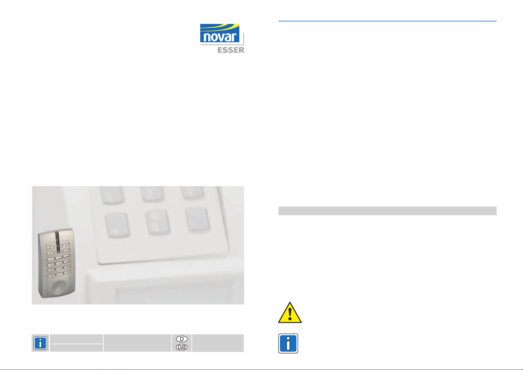
7Montage-Anschluß-Anleitung Novar R/W-Leser mit Tastatur 026421
6. Inbetriebnahme
6.1 Hinweis zur Bedienung mit Transpondern
6.2
Der Transponder ist etwa zu halten.
Um bei der Transponder-Benutzung eine große Übertragungsreichweite zu erzielen, wird während
der Übertragung ein relativ hoher Strom benötigt (<50 mA).
Ohne Transponderübertragung (5 Sek. nach der letzten Übertragung) schaltet der Leser vom
aktiven automatisch in den Stromsparbetrieb und reduziert dadurch den Strom-
verbrauch im Mittel auf <11 mA.
Wird der Transponder einem Leser im Stromsparbetrieb genähert, kann es bis zu
1,2 Sek. dauern, bis er bearbeitet ist. Im aktiven erfolgt die Auswertung
innerhalb von 0,9 Sek.
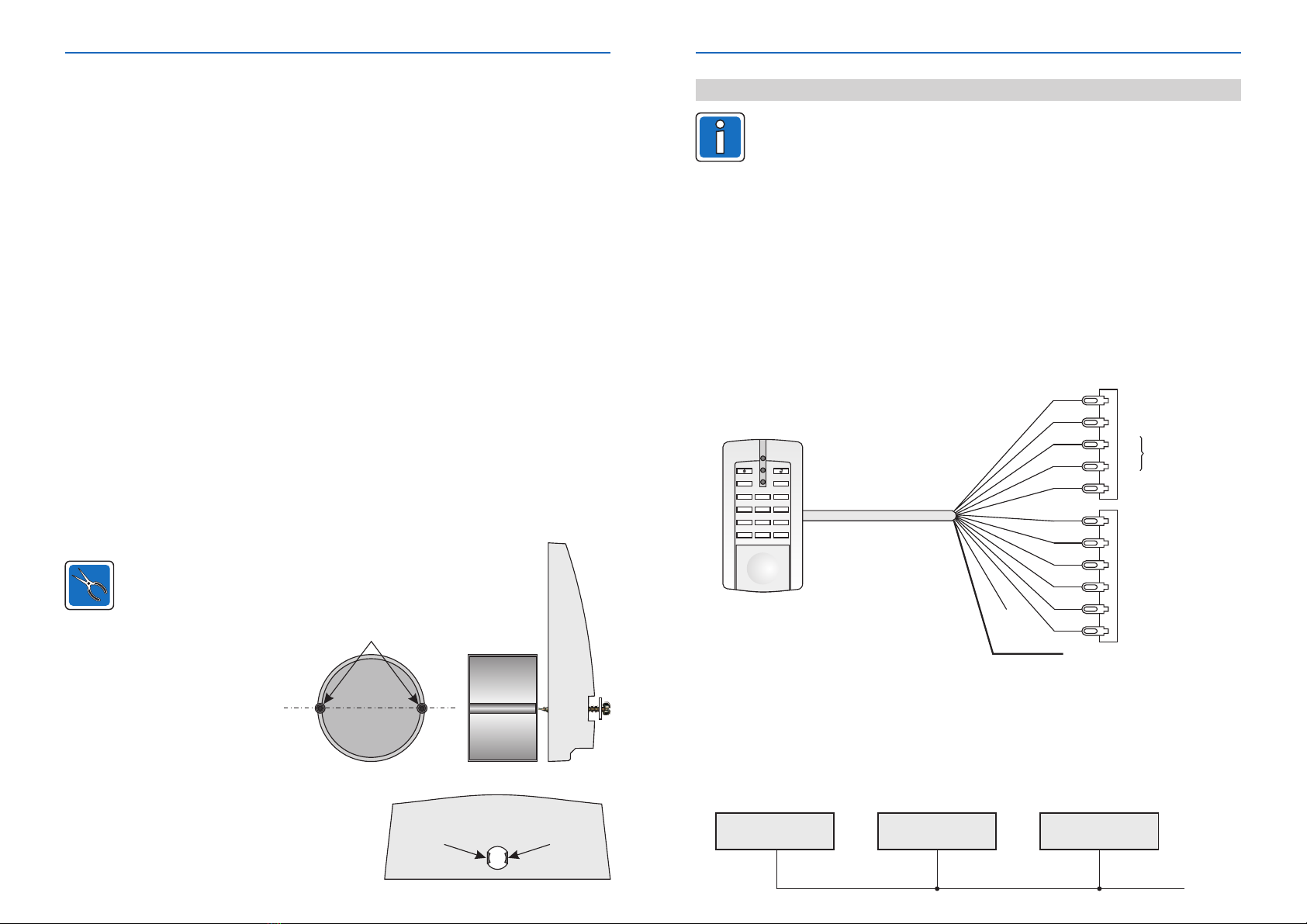
Bei Montageuntergrund aus Metall kann die Übertragungsreichweite der Transponder
geringer sein als auf nichtmetallischem Untergrund. In diesem Fall wird ein Abgleich der
Reichweite dringend empfohlen ( ).
(Nur erforderlich bei Verwendung der RS-485-Schnittstelle)
Bei dieser Adressvergabe ist zu berücksichtigen, daß möglich ist.
Dies bedeutet, daß es im späteren Betrieb zu einer Adresskollision kommen kann (Doppel- oder
Mehrfachadressierung).
Voraussetzung für die stand alone Adressvergabe:
Der Leser wird neu an die Betriebsspannung (12 V DC), ange-
schlossen.
Anschließend kann über die Tastatur die Adresse (1 oder 2-stellig) eingegeben und mit OK (Taste
bestätigt werden. Die Adresse wird beim Abklemmen der Betriebsspannung im Leser gespeichert.
Eine Überschreibung der Adresse ist möglich, solange der Leser von der ZK-Zentrale noch nicht
aufgenommen ist und die Betriebsspannung nicht unterbrochen wurde.
: Wird der Leser später mit der ZK-Zentrale verbunden, so wird die eingegebene Adresse
zusammen mit der zur ZK-Zentrale gesendet und dort abge-
speichert.
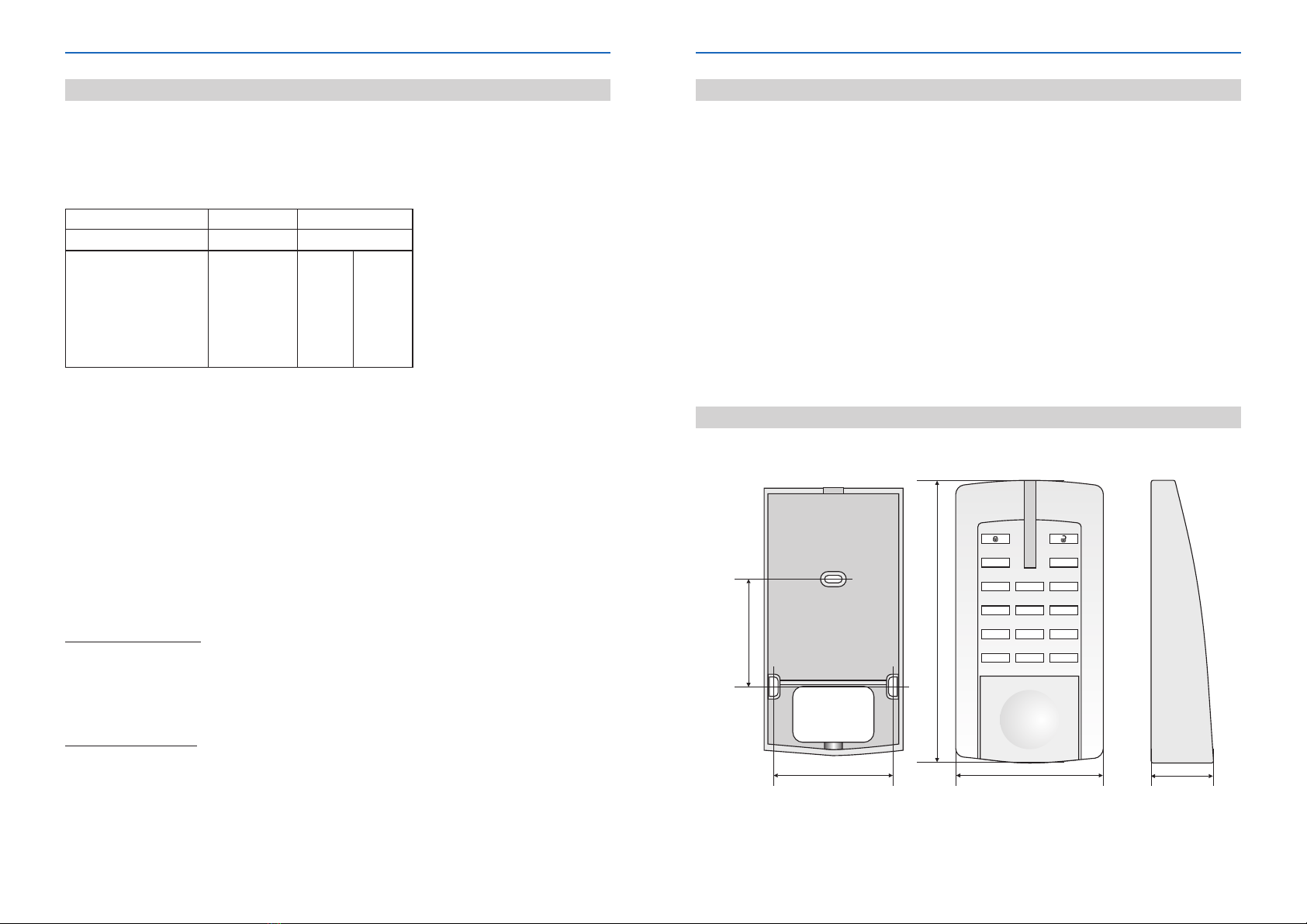
mittig vor die Tastatur
keine Plausibilitätsprüfung
Adresse vergeben
Adresse überschreiben
Adresse löschen
Achten Sie darauf, daß in einem System eine Adresse nicht doppelt oder mehrfach
vergeben wird!
und nur an die Betriebsspannung
Hinweis
Lesebetrieb
Lesebetrieb
)
Eine Adresse wird gelöscht, wenn im spannungslosen Zustand die und gleich-
zeitig gedrückt und festgehalten werden, während die Betriebsspannung wieder angelegt wird.
Außerdem kann eine Adresse auch im "Stand alone Programmiermodus" gelöscht werden ( ).
Leser-Unikatnummer
Adressvergabe über die Lesertastatur im "stand alone" Betrieb
3
Tasten "1", "7" "X"
siehe 7.4
siehe 7.2
8
7. Stand alone Programmiermodus
nur die BetriebsspannungZur Durchführung der Programmierung in diesem Modus ist von 12 V DC
erforderlich.
Im spannungslosen Zustand die Tasten mit den nebenstehenden Symbolen
gleichzeitig drücken und festhalten.
Betriebsspannung anlegen. Sobald der Programmiermodus aktiviert ist, blinken die
drei LEDs im Sekundentakt. Tasten loslassen.
7.1 Programmiermodus aktivieren
I
7.2 Adresse löschen
7.3 Standardwerte laden
7.4 Abgleichmodus Reichweite
Durch Betätigen der wird eine bereits vergebene Adresse gelöscht.
Durch Betätigen der wird der Auslieferungszustand hergestellt.:
- Reichweite: 6 cm bei Karten
- Hintergrundbeleuchtung: im Ruhezustand ausgeschaltet
- Transponder-Erfassung: zyklische Ansteuerung (Stromsparmodus)
Eine bereits vergebene Adresse bleibt erhalten.
Im Abgleichmodus besteht die Möglichkeit, die Übertragungsreichweite zwischen Leser und
Transponder zu verändern. Zu beachten ist, daß je nach Montageuntergrund eine Mindest- und
Maximalreichweite nicht unter- oder überschritten werden kann.
Grundsätzlich sollte die Reichweite auf einem metallischen Montageuntergrund angepaßt werden.
Es ist davon auszugehen, daß die maximal mögliche Übertragungsreichweite bei einem Untergrund
aus Metall geringer ist als auf einer nichtmetallischen Montagefläche.
Ein beliebiger wird im gewünschten Abstand zum Leser gehalten. Die Leseeinheit
verändert nun stufenweise die Energie des elektromagnetischen Feldes (16 Stufen von max. bis
min.) und überprüft, bei welcher Energiestufe der Transponder gerade noch fehlerfrei gelesen
werden kann. Dieser Zyklus wird zweimal hintereinander durchlaufen. Der so ermittelte Wert wird
nichtflüchtig (bis zum nächsten Abgleich) im Leser abgespeichert und dient für künftige
Anwendungen als Grenzwert für die maximale mögliche Reichweite.
Bei diesem Reichweitenabgleich handelt es sich nicht um eine hochpräzise Justierung. In
erster Linie soll dieser Modus dazu dienen, daß der Leser auch auf metallischem
Montageuntergrund noch korrekt arbeitet.
Durch Betätigen der wird der
Abgleichmodus Reichweite aktiviert.
Taste "1"
Taste "2"
Funktion des Abgleichvorgangs:
Abgleichmodus aktivieren:
Taste "3"
³
Transponder
Montage-Anschluß-Anleitung Novar R/W-Leser mit Tastatur 026421
FI
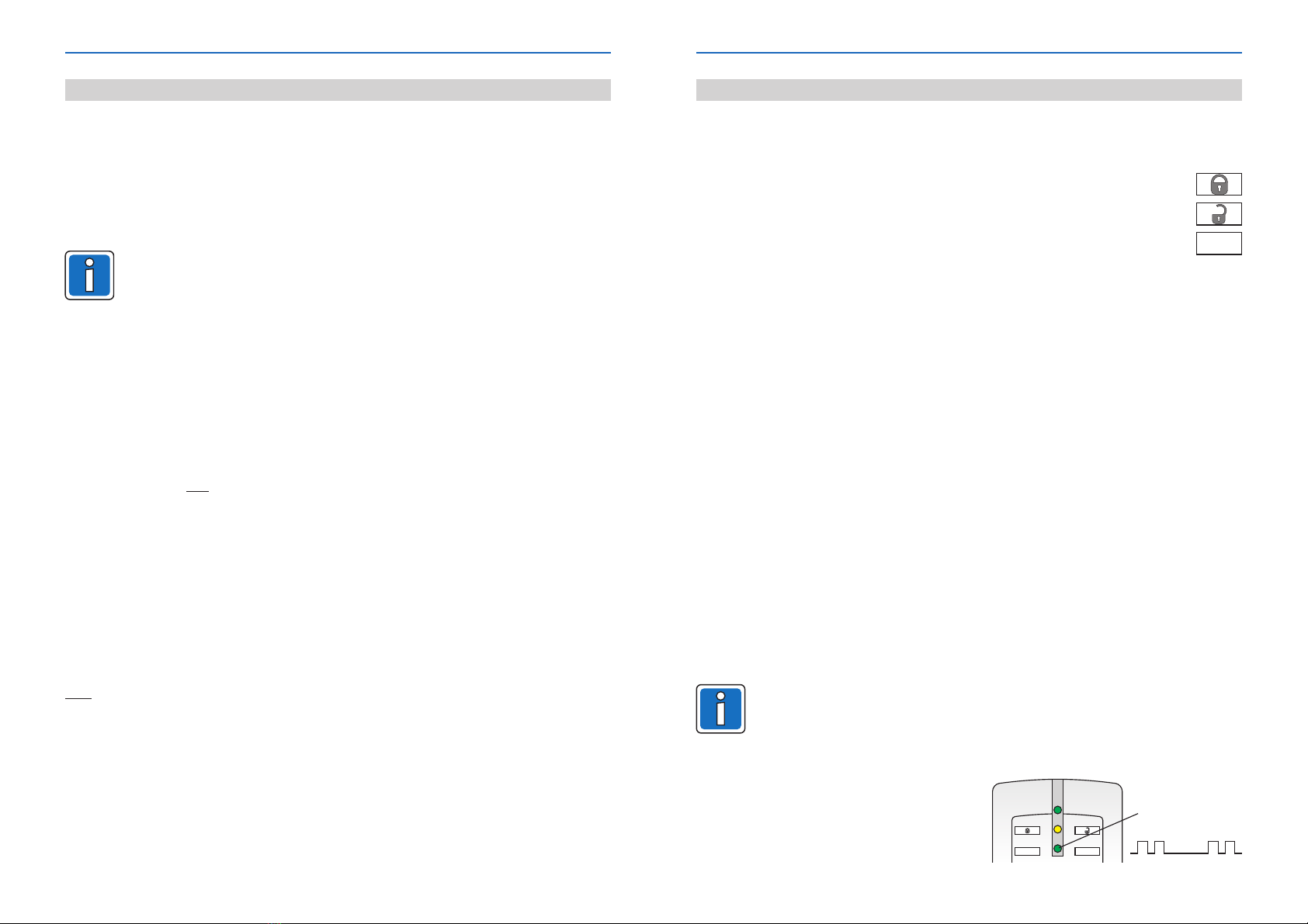
Abgleichmodus
aktiviert
Am Leser wird der aktivierte Abgleichmodus
durch ein zweimaliges kurzes Blinken der
unteren grünen LED mit anschließend längerer
Pause angezeigt.