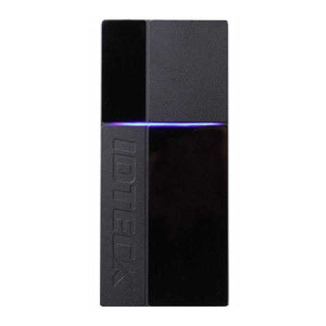
IDTECK RF900I-8 User manual

User Manual
1
RF900I-8
User Manual

User Manual
2
Catalogue
1.RF900I-8 VIEW................................................................................................................................................3
1.1 FRONT VIEW......................................................................................................................................................3
1.2 BACK VIEW........................................................................................................................................................3
2.RF900I-8 CONFIGURATIONS....................................................................................................................4
2.1 INITIAL USE........................................................................................................................................................4
2.1.1 STEP 1: POWERING THE READER ......................................................................................................................4
2.1.2 STEP 2: CONNECTING ANTENNA(S)TO READER...............................................................................................4
2.1.3 STEP 3: CONNECTING DATA LINE TO READER .................................................................................................4
2.1.4 STEP 4: OPERATING READER VIA DEMO ..........................................................................................................4
2.2 SETTING RFPARAMETER..................................................................................................................................7
2.2.1 SETTING RF OUTPUT POWER...........................................................................................................................7
2.2.2 SETTING RF SPECTRUM ...................................................................................................................................8
2.2.3ANTENNA CONNECTION DETECTOR.................................................................................................................9
2.2.4 MEASURE RF PORT RETURN LOSS.................................................................................................................10
2.3 ISO-18000-6CTAG INVENTORY......................................................................................................................10
2.3.1 REAL TIME MODE ..........................................................................................................................................10
2.3.2 USERS DEFINE SESSION ID &INVENTORYING PARAMETER OF INVENTORIED FLAG.....................................13
2.3.3 FAST SWITCHING ANTENNATO INVENTORY TAGS.........................................................................................14
2.4ACCESSING ISO-18000-6CTAG......................................................................................................................15
2.4.1READ TAGS......................................................................................................................................................16
2.4.2 WRITE TAGS ...................................................................................................................................................17
2.4.3 LOCK TAGS.....................................................................................................................................................19
2.4.4 KILL TAGS......................................................................................................................................................20
2.4.5 TAG SELECTION..............................................................................................................................................20
2.4.6 ERROR DISPLAY MIGHT BE RETURNED.........................................................................................................21
2.5 OTHER SETTINGS ............................................................................................................................................22
2.5.1OPERATING TEMPERATURE MONITORING.......................................................................................................22
2.5.2 SET GPIO LEVEL ...........................................................................................................................................22
2.5.3 SETTING BUZZER STATUS ..............................................................................................................................23
2.5.4 CHANGING THE SERIAL COMMUNICATION BAUD RATE................................................................................23
3 DEVELOPYOUR OWN RFIDAPPLICATION ...........................................................................................24
User Manual
3
1.RF900I-8 View
1.1 Front View
1.2 Back View

User Manual
4
2.RF900I-8 Configurations
2.1 Initial Use
2.1.1 Step 1: Powering the reader
Plug the power cable in, with the indicator light on and sound of a short beep, reader is ready.
2.1.2 Step 2: Connecting Antenna(s) to reader
Connect the antenna(s) with the antenna port:
2.1.3 Step 3: Connecting Data Line to Reader
Method NO.1: You can connect the reader to your PC via RS-232 serial port:
Method NO.2: You can also connect the reader to your PC via TCP/IP:
2.1.4 Step 4: Operating Reader via Demo
Put the UHFDemo.exe, reader.dll, customControl.dll into the same folder, and double-click
UHFDemo.exe to run the software.
Open the software and it will shows as below:

User Manual
5
If the reader is connected via RS232, please select "RS232" in the connection mode, select the corresponding serial
port number, and select the corresponding baud rate. The default baud rate is 115200. As shown below:
Then click the "Connect " button, if the serial port is not occupied, the following information will be displayed in the
Operation History below:
If the reader is connected via TCP/IP, you need to perform the following steps:
1. Make sure there is an Ethernet card in the PC.
2. Make sure that the settings of the PC and the reader are in the same network segment.
The reader as a server uses the following default settings:
IP address: 192.168.0.178

User Manual
6
Subnet mask: 255.255.255.0
Port number: 4001
For specific TCP/IP configuration, please refer to the accompanying document: \TCP-IP
configuration\USR-TCP232-ED2 network module detailed instructions-20190624.
When using the reader for the first time, please select the configuration shown in the figure below in the connection
mode:
Click the "Connect "button, if the connection is successful, the following information will be displayed in the
Operation History blow:
Next we will test the communication with the reader.
Click the button at the position shown in the oval frame in the figure below.
Click the button to read the firmware version, or click the button to read the reader identification , the interface will
display the corresponding information in the rectangular frame, as shown in the following figure:

User Manual
7
At this point, the connection between the reader and the computer has been successfully completed.
2.2 Setting RF Parameter
After successfully connecting the reader with PC, we need to set some of the most basic RF parameters, such as RF
output power and RF spectrum.
RF parameter setting is in the Reader Setup->RF Setup page, as shown in the figure below:
2.2.1 Setting RF Output Power
RF Output Power is the strength of RF output signal from antenna port whose unit is dBm.

User Manual
8
The power range is 0dBm-33dBm, in increments of 1dB. The default value is 33dBm (2W). After this value is
set, it will be automatically saved in the reader and will not be lost after the reader is powered off. The default
RF output power is 33dBm.
To set the output power of the 8 antenna ports at the same time, you only need to enter the required power value in
port 1, and the power values of the following ports will automatically follow port 1, as shown in the following figure:
To set the output power of the 8 antenna ports independently, you need to first enter the power value you need to set in
port 1, and then enter the power value you need to set in the other required setting ports, as shown in the following
figure:
2.2.2 Setting RF Spectrum
In different regions, there are different requirements for the RF Spectrum. There are two ways to set the RF Spectrum
of the reader.
Method 1: Use the default carrier frequency of the reader.
Please refer to Frequency parameter tablet in Communication protocol for more information about the carrier
frequency.
Frequency range the reader supports: 865MHz-868MHz (ETSI), 902MHz -928MHz (FCC).
Set the desired carrier frequency through the drop-down box and button as shown in the figure below.
Notes:
The start frequency and the end frequency must not exceed the scope of RF spectrum norm.
Start frequency must be no more than end frequency.
Set start frequency and end frequency to the same carrier frequency, the reader will work under fixed-frequency.
When the parameter setting completes, RF carrier frequency of reader will be randomly hopping in the scope of

User Manual
9
limited range.
The default RF spectrum norm is FCC (902MHz-928MHz).
Method 2: Set the RF spectrum manually.
The user customizes the spectrum through three parameters: the starting frequency (unit is KHz, such as 860MHz, you
need to enter 860,000), the interval between frequencies (the unit is KHz, the maximum frequency interval is
2500KHz, if you enter 2.5MHz, you need to enter 2500), the number of frequency points (Select the number of
frequency points according to the input start frequency and frequency interval. The recommended maximum operating
frequency range is 860MHz ~ 960MHz. When the number of frequency points is 1, work at fixed frequency according
to the start frequency).
For example, if you need to customize the working frequency range from 860MHz to 960MHz, you can get the
starting frequency of 860MHz, the frequency interval is 2.5MHz, and 40 frequency points are needed. Then enter the
corresponding parameters as shown in the figure below. After this value is set, it will be automatically saved in the
reader and will not be lost after the reader is powered off.
2.2.3Antenna Connection Detector
The function of antenna connection detection is to check whether the antenna is connected to the port before reading
and writing tags. If there is no connection, notify the user that the antenna is not connected.
Before use, the user needs to turn on this function and view it through the interface shown in the figure below. The
interface for setting this function is shown in the figure below:
The sensitivity of antenna detection is set by the user. The sensitivity of antenna detection is the return loss value
(Return Loss) of the antenna port, and the unit is dB. The larger the value, the better the impedance matching
requirement between the antenna and the antenna port. Generally speaking, for antennas with an antenna port standing
wave VSWR ≤ 1.3, this threshold can be set to 3 to 6 dB. For near-field antennas, ceramic antennas or handheld
terminal antennas with VSWR ≥ 1.3, the sensitivity can be lowered even lower. If the return loss threshold is set to 0,
it means that this function is turned off, and the antenna connection status will not be detected before reading and
writing tags.
If antenna is not connected, Reader will stop to operate tags with the following screen display:

User Manual
10
2.2.4 Measure RF Port Return Loss
Measure the return loss of the antenna port on the interface as shown in the figure below:
Before measuring, you need to set the current working antenna port. The default antenna working port is 1. When
measuring the return loss of other antenna ports, you need to set the corresponding working antenna.
In the actual application environment, the working status of the environment in front of the antenna can be
preliminarily determined by reading the return loss value of each frequency point of the current working antenna. The
larger the return loss value, the smaller the electromagnetic wave reflection in front of the antenna. If the measured
return loss of the antenna product port is less than or equal to 10dB, it indicates that the electromagnetic wave
reflection in front of the antenna is too large. At this time, it is necessary to reduce the RF output power or adjust the
antenna installation position. The return loss of the antenna port and VSWR are two different expressions of the same
concept. The corresponding relationship is shown in the following table:
Return loss of antenna port (dB)
Standing wave ratio (VSWR) of antenna port
40
1.02
26
1.11
20
1.22
18
1.29
15
1.43
10
1.92
2.3 ISO-18000-6C tag inventory
After correctly connecting the reader and setting the RF parameters, you can read and write tags.
Inventory tags, that is, recognizes the EPC code of multiple tags at the same time.This is the core funtion of UHF
RFID Reader and one of the standards to judge a reader’s performance.
2.3.1 Real Time Mode
The most commonly used mode is the real-time mode, which means uploading immediately after reading the EPC
number of the tag. The user can get the EPC number of the tag as soon as possible.
The advantage of the real-time mode is that the multi-tag recognition performance is good, the response is fast, and
the user can get the tag data in the first time without delay. And RSSI (tag signal strength indicator), frequency

User Manual
11
parameter (carrier frequency when the tag is read) also change in real time. But it will generate a lot of data. The
reader adopts a dual-CPU architecture. Two different chips are responsible for reading tags and transmitting tag data.
Reading tags and transmitting tag data are parallel, without interfering with each other, and not occupying each other's
time, so users do not need to worry Data transmission will reduce the read performance of multiple tags. Therefore,
the multi-tag recognition performance in real-time mode is the best.
Inventory tags in real-time mode.
Click Tag Inventory (Real time mode) page to switch the software interface to real time mode. Manually tick the
connected antenna. Then set the number of cycles for each command. The meaning of this parameter is the number of
repeated executions of the inventory command. For example, if it is set to 1, each inventory command executes an
anti-collision algorithm. Set to 2, then each inventory command will execute the anti-collision algorithm twice, and so
on. The default setting is 1 (the bottom layer of the reader does not support setting other values).
Next, click the "Inventory" button and read the EPC number of the tag. We can see that the EPC data of the tag is
immediately uploaded and updated in real time. If you do not click the "Stop" button, the reader will keep real-time
inventory tags, as shown in the following figure:

User Manual
12
The meaning of the data display is as follows:
Inventoried Quantity
Total number of inventory tags since click on Inventory Tag.
Speed
Speed of identification Tag, unit: piece / sec
Total Tag Communication
Total return EPC data of tags (Including repeated data)
Command Duration
Time of each Inventory Command takes, unit: ms
Total Inventory Duration
Total elapsed time since click on Inventory Tag, unit: ms.
ID
The serial number of data.
EPC
EPC number of tag.
PC
Protocol Control word of tag.
Identification Count
Times of tag identified.
RSSI
The signal strength when tag was identified at the last time.
Carrier Frequency
Carrier Frequency of tag which is identified at the last time.
It is convenient for users to analyze the inventory data, and can choose to save the inventory data such as the tag EPC
number in TXT or EXCEL, as shown in the figure below.

User Manual
13
2.3.2 Users define Session ID & Inventorying Parameter of Inventoried Flag
According to the user-defined Session ID and Inventoried Flag parameters to inventory, the reader can inventory
according to the user-defined session parameters (four types of session S0, S1, S2, S3) and the inventoried flag (two
inventoried flagsA, B) parameters .

User Manual
14
2.3.3 Fast SwitchingAntenna to Inventory Tags
In the operation of standard inventory tags (real time mode, each antenna needs to be commanded to set the
corresponding working antenna before inventory), a single antenna inventory requires at least 200 milliseconds. Only
after the inventory is completed, the reader can respond to new commands.
However, in many practical application environments, it is unacceptable to switch the antenna after 200 milliseconds.
At this time, the function of quickly switching the antenna of the inventory tag needs to be used.
Use cmd_name_fast_switch_ant_inventory command (see R2000 module serial interface communication protocol
V4.0).
With this command, users do not need to send antenna switching commands, so it is faster and more efficient. On one
antenna, the time consumed to read one or two tags is only about 50 milliseconds. Please refer to R2000 module serial
interface communication protocol V4.0 for the specific usage of this command.
We can see the effect of fast 8-antenna inventory tag in the demo program.
Switch the demo program to the fast 8-antenna inventory interface, as shown in the figure below:

User Manual
15
The working time of each antenna can be set independently. The number of round 1 means that the working time of
the antenna is 50ms, and the number of round*50ms is the working time of the antenna. Set the appropriate number of
round according to the number of tags in front of the antenna. The default number of round is 1.
The sequence of antenna switching and whether to select the antenna inventory can be set as shown in the figure
below.
2.4 Accessing ISO-18000-6C Tag
Click the "Access Tag" selection box to enter the access tag interface, as shown below:

User Manual
16
The following will introduce how to access tags one by one.
2.4.1Read tags
The parameters for reading tags are entered in the interface shown in the figure below:
Three parameters need to be input to read tags: select the tag storage area to be read, start address and data length.
Note: The units of the start address and data length here are both WORD, which is a double byte of 16 bits. After
setting the parameters, click the “Read” button.
It should be noted that the input parameters must meet the tag specifications, otherwise an error message will appear.
The specific read tag operation is shown in the figure below:
(1) Select the tag that needs to be operated (read in the real-time inventory interface, and all the read tags will be
displayed in the drop-down list), and click the "Selected " button on the right.
(2) Select the storage area that needs to operate the tag. In the example, select the EPC storage area.
(3) Enter the access password, the default is 00 00 00 00.
(4) Enter the starting address and data length. The upper four bytes of the EPC storage area are two bytes of CRC and
two bytes of PC, so the starting address of the EPC number is 02 (unit word, Start reading after the upper four bytes).

User Manual
17
Data length input 6 (unit word, read 12 bytes).
(5) Click "Read " to read the contents of the corresponding storage area of the tag and display it in the data column of
the list box.
As many tags are manipulated, how many pieces of data will be displayed in the list.
2.4.2 Write tags
The interface of the tag writing operation and the reading operation are in the same area. The difference is that the
writing operation also needs to provide information such as access password and writing data.
The password area is the part of the password (password) in the tag storage area. Including kill password and access
password. Both the kill password and the access password are 4 bytes. Among them: the address of the inactivation
password is 00H~03H (in bytes); the address of the access password is 04H~07H (in bytes).
The specific tag writing operation is shown below:
(1) Select the tag that needs to be operated (read in the real-time inventory interface, and all the read tags will be
displayed in the drop-down list), and click the "Select" button on the right.
(2) Select the storage area that needs to operate the tag. In the example, select the EPC storage area.

User Manual
18
(3) Enter the access password, the default is 00 00 00 00.
(4) Enter the starting address and data length. The upper four bytes of the EPC storage area are two bytes of CRC and
two bytes of PC, so the starting address of the EPC number is 02 (unit word, Start reading after the upper four bytes).
Data length input 6 (unit word, write 12 bytes).
(5) Enter the data to be written in the "Data to be written (HEX)", such as "112233445566778899AABBCC", 12
bytes.
(6) Click the "Write" button to write the content that needs to be written into the corresponding storage area of the tag
and display it in the data column of the list box.
How many tags are successfully operated, how many pieces of data will be displayed in the list. Unlike reading tags,
there is no content in the data column in the figure above. The user can read the same area of the tag again to verify
that the data is written correctly. As shown below:

User Manual
19
Note that the maximum write length at one time is 32 Words (64 bytes, 512bits).
2.4.3 Lock Tags
The operation interface of the lock tag is shown in the figure below:
The lock tag must provide an access password to proceed.
After the operation is successful, the following information will be returned:
Similarly, how many tags are operated, how many pieces of data will be displayed in the list.

User Manual
20
2.4.4 Kill Tags
The operation interface of the kill tag is shown in the figure below:
The killing tag must provide an kill password, and the kill password cannot be 00 00 00 00. Therefore, to kill a tag,
you must first modify the content of the kill password in the password area through the write tag command.
After the tag is successfully killed, the following information will be returned:
Like all operations of accessing tags, how many tags are killed, how many pieces of data are displayed in the list.
2.4.5 Tag Selection
In many cases, we hope that no matter how many tags there are in the radio frequency area, only one tag with a known
EPC number can be accessed. At this time, the tag function (EPC matching function) of the selected operation needs
to be used.
In the accompanying demo software, taking the real-time inventory mode as an example, the operation is as follows:
First, use real-time inventory mode to inventory tags, and get all EPC numbers.
Then go to the interface of access label and select the EPC number to be matched.As shown below:
Table of contents
Other IDTECK Card Reader manuals

IDTECK
IDTECK SRK101 User manual

IDTECK
IDTECK Star RF30 User manual

IDTECK
IDTECK SR10S User manual

IDTECK
IDTECK Star RF TINY User manual

IDTECK
IDTECK Star SR10 User manual

IDTECK
IDTECK Star RFK101 User manual

IDTECK
IDTECK ipass IP10 User manual

IDTECK
IDTECK Star RFK101 User manual

IDTECK
IDTECK SR30 User manual

IDTECK
IDTECK Star RFK505 User manual

IDTECK
IDTECK PROX10 User manual

IDTECK
IDTECK Star SR10 User manual

IDTECK
IDTECK Star RFK505 User manual

IDTECK
IDTECK PROX10 User manual

IDTECK
IDTECK SR10/30V User manual

IDTECK
IDTECK Star SR10 User manual

IDTECK
IDTECK Star RFK101 User manual

IDTECK
IDTECK SR10RW User manual

IDTECK
IDTECK Star RFK101 User manual

IDTECK
IDTECK Star FINGER006 User manual