Novelan Compact Station Dual User manual
Operating Manual
UK
Accessories for
Dual Air/ Water Heat Pumps
Compact Station Dual
83053803dUK – Translation into English of the original German operating manual – Subject to change without notice. www.novelan.com
283053803dUK – Translation into English of the original German operating manual – Subject to change without notice. www.novelan.com
Please read rst
This operating manual provides important information
on the handling of the unit. It is an integral part of the
product and must be stored so that it is accessible in the
immediate vicinity of the unit. It must remain available
throughout the entire service life of the unit. It must be
handed over to subsequent owners or users of the unit.
Read the operating manual before working on or
operating the unit. This applies in particular to the
chapter on safety. Always follow all instructions
completely and without restrictions.
It is possible that this operating manual may contain
instructions that seem incomprehensible or unclear. In
the event of any questions or if any details are unclear,
contact the factory customer service department or the
manufacturer’s local partner.
As this operating manual has been written for several
unit models, always comply with the parameters for the
respective model.
This operating manual is intended only for persons
assigned to work on or with the unit. Treat all constituent
parts condentially. The information contained herein is
protected by copyright. No part of this manual may be
reproduced, transmitted, copied, stored in electronic
data systems or translated into another language, either
wholly or in part, without the express written permission
of the manufacturer.
Symbols
The following symbols are used in the operating manual.
They have the following meaning:
Information for operators.
Information or instructions for qualied
personnel.
DANGER!
Indicates a direct impending danger
resulting in severe injuries or death.
WARNING!
Indicates a potentially dangerous situation
that could result in serious injuries or death.
CAUTION!
Indicates a potentially dangerous situation
that could result in medium or slight injuries.
IMPORTANT
Indicates a potentially dangerous situation,
which could result in property damage.
NOTE.
Emphasized information.
€ENERGY SAVING TIP
Indicates suggestions that help to save energy,
raw materials and costs.
Reference to other sections of the operating
manual.
Reference to other documents of the
manufacturer.

383053803dUK – Translation into English of the original German operating manual – Subject to change without notice. www.novelan.com
Contents
INFORMATION FOR USERS AND QUALIFIED
PERSONNEL
PLEASE READ FIRST.......................................................................2
SYMBOLS..........................................................................................2
INTENDED USE................................................................................4
DISCLAIMER.....................................................................................4
SAFETY..............................................................................................4
CUSTOMER SERVICE......................................................................5
WARRANTY / GUARANTEE...........................................................5
DISPOSAL .........................................................................................5
HEAT METERING.............................................................................5
OPERATION......................................................................................5
CARE OF THE UNIT.........................................................................6
MAINTENANCE OF THE UNIT......................................................6
MALFUNCTIONS.............................................................................6
INSTRUCTIONS FOR QUALIFIED PERSONNEL
SCOPE OF DELIVERY......................................................................7
INSTALLATION AND ASSEMBLY .................................................7
Installation location ................................................................7
Transport to installation location........................................7
Facilitating transport ..............................................................8
Installation.................................................................................8
Components of the unit.........................................................8
Installation / Hydraulic connection to heating circuit
and domestic hot water ..................................................9
Hydraulic connection of hot water tank..........................10
ELECTRICAL CONNECTIONS .....................................................10
Connect BUS cable ................................................................ 11
FLUSHING, FILLING AND VENTING THE SYSTEM ................12
Flushing, filling and venting the heating circuit ...........12
Venting the circulating pump of the heating circuit ....12
flushing, filling and venting the domestic hot water
tank.....................................................................................13
INSULATING THE HYDRAULIC CONNECTIONS....................13
SET THE OVERFLOW VALVE.......................................................13
INSTALLATION OF THE CONTROL UNIT.................................14
COMMISSIONING .........................................................................14
Safety temperature limiter..................................................15
DISMANTLING...............................................................................15
TECHNICAL DATA/ SCOPE OF DELIVERY ...............................16
PERFORMANCE CURVES
Heating capacity/COP / power consumption /
Heat pump pressure loss
FREE COMPRESSION....................................................................18
DIMENSIONED DRAWINGS........................................................19
INSTALLATION PLAN...................................................................20
HYDRAULIC INTEGRATION
Compact Station Dual / LAD...............................................22
Legend Hydraulic integration.............................................23
TERMINAL DIAGRAM...................................................................24
CIRCUIT DIAGRAMS.....................................................................25
EC DECLARATION OF CONFORMITY.......................................27
483053803dUK – Translation into English of the original German operating manual – Subject to change without notice. www.novelan.com
Intended use
The hydraulic tower is an accessory for air/water heat
pumps intended for outdoor installation. Taking into
account its performance limits, the unit can be used in
combination with an outdoor installation air/water heat
pump in new or existing heating systems.
The unit may be used only for its intended use. This
means in combination with an LAD ... A:
•for heating.
•for domestic water heating.
The unit may be operated only within its technical
parameters.
Overview “Technical data / Scope of delivery”
and overview “Technical data /Scope of
delivery” of the operating manual for the heat
pump to which the hydraulic tower is connected.
WARNING!
Do not exceed the operating pressures
specied on the rating plate.
NOTE.
Notify the responsible power supply company
of the use of a heat pump or heat pump system.
Disclaimer
The manufacturer is not liable for losses resulting from
any use of the unit which is not its intended use.
The manufacturer’s liability also expires:
•if work is carried out on the unit and its
components contrary to the instructions in this
operating manual.
•if work is improperly carried out on the unit and
its components.
•if work is carried out on the unit which is not
described in this operating manual, and this
work has not been explicitly approved by the
manufacturer in writing.
•if the unit or components in the unit have been
altered, modied or removed without the explicit
written consent of the manufacturer.
Safety
The unit is safe to operate for its intended use. The
construction and design of the unit conform to current
state of the art, all relevant DIN/VDE regulations and all
relevant safety regulations.
Every person who performs work on the unit must
have read and understood the operating manual prior
to starting any work. This also applies if the respective
person has already worked with such a unit or a similar
unit or has been trained by the manufacturer.
Every person who performs work on the unit must
comply with the applicable accident prevention and
safety regulations. This applies in particular to the
wearing of personal protective equipment.
DANGER!
Risk of fatal electric shock!
Electrical connection work must be carried
out by qualied electricians only.
Before opening the unit, disconnect the
system from the power supply and prevent it
from being switched back on!
WARNING!
Only qualied personnel (trained heating,
cooling and electricians) may carry out work
on the unit and its components.
IMPORTANT
For safety reasons:
Never disconnect the unit from the power
supply, unless the unit is being opened.
583053803dUK – Translation into English of the original German operating manual – Subject to change without notice. www.novelan.com
Customer service
For technical information please contact your local
heating engineer or the manufacturer’s local partner.
For a current list and additional partners of the manuf-
acturer, please visit www.novelan.com.
Warranty / Guarantee
For warranty and guarantee conditions, please refer to
the purchase documents.
NOTE.
Please contact your dealer about all matters
concerning warranties and guarantees.
Disposal
When decommissioning the unit, always comply
with applicable laws, directives and standards for
the recovery, recycling and disposal of materials and
components.
“Dismantling”.
Heat metering
In addition to proof of the unit’s eciency, the
EEWaermeG (German law on renewable energy heat)
also requires heat metering (hereafter also referred to
as HQR). Heat metering is mandatory for air/water heat
pumps. Heat metering for brine/ water and water/water
heat pumps has to be installed for ow temperatures
≥ 35°C. The heat metering must record the total thermal
energy released (heating and domestic hot water) in the
building. In the case of heat pumps with heat metering
the analysis is carried out via the regulator. It displays
the thermal energy delivered in the heating system in
kWh.
Operation
Your decision to purchase a heat pump or a heat pump
system is a long-term contribution to protecting the
environment through low emissions and reduced
primary energy use.
You can operate and control the heat pump system with
the control unit of the heating and heat pump regulator.
NOTE.
Make sure that the control settings are correct.
Operating manual of the heating and heat
pump regulator.
To ensure that your heat pump or heat pump system
operates eciently and ecologically, the following are
especially important:
€ENERGY SAVING TIP
Avoid unnecessarily high ow temperatures.
The lower the ow temperature on the heating
water side the more ecient the system.
€ENERGY SAVING TIP
Preferably use purge ventilation. Compared
to continuously open windows, it is better to
air rooms by fully opening windows for a short
period, two to three times a day (so-called
“rapid” or “purge” ventilation); this reduces
energy consumption and your heating bill.
683053803dUK – Translation into English of the original German operating manual – Subject to change without notice. www.novelan.com
Care of the unit
You can clean the outer surfaces of the unit with a damp
cloth and proprietary household cleaning products.
Do not use cleaning or care products that contain
abrasives, acids and/or chlorine. Such products would
irreparably damage the surfaces and could also cause
technical damage to the unit.
Maintenance of the unit
The components of the heating circuit (valves,
expansion vessels, circulating pumps, lters, dirt traps)
should be inspected or cleaned as needed, at the
very least annually, by qualied personnel (heating or
cooling system engineers).
The hot water tank should be cleaned once a year
by qualied personnel (heating or cooling system
engineers). To do this, rst empty the hot water tank.
Then remove the polystyrene guard over the service
opening of the hot water tank. Unscrew the ange cover
of the service opening.
Check the safety valve (provided by customer) for the
hot water tank at regular intervals. Have the magnesium
anode checked and if necessary renewed by the
customer service for the rst time after 2 years and then
at appropriate intervals.
Renew anode if protective current lower than 0.3 mA.
After replacing anode, re-install earthing cable between
anode and storage tank jacket.
Ideally you should arrange a maintenance agreement
with a heating installation company. It will arrange for
the necessary maintenance work at regular intervals.
Malfunctions
In case of malfunctions, you can read out the cause of
the fault from the diagnostics program of the heating
and heat pump regulator.
Operating manual for the heating and heat
pump regulator.
IMPORTANT
Only customer service personnel authorised
by the manufacturer may carry out service and
repair work on the unit’s components.
Note that no fault is displayed if the safety temperature
limiter on the electric heating element has tripped.
“Commissioning”, “Safety temperature limiter”
section.
7
83053803dUK – Translation into English of the original German operating manual – Subject to change without notice. www.novelan.com
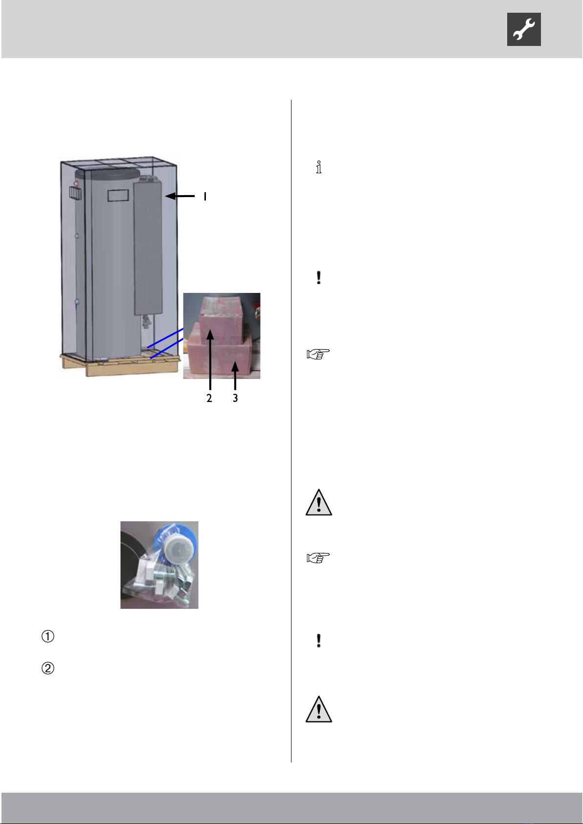
Scope of delivery
Sample layout of the scope of delivery:
Fertigungsanweisung Hydrauliktower HTD Verpackung:
Benennung:
Zeichnungsnummer:
Fertigungsanweisung Hydrauliktower
HTD Verpackung
802446
Blatt 7/8
Datum
Name
Erstellt
12.06.2012
Aepfelbach
Gepr.
Zust.
Änderungstext
Datum
Von
Norm.
600603
Schaumzuschnitte 20x10
aufkleben
607854
Karton
901x656x1792
600603
2x Schaumzuschnitte 20x10
übereinander
aufkleben
Holzleisten
aus Speicherverpackung
von SBT
Fertigungsanweisung Hydrauliktower HTD Verpackung:
Benennung:
Zeichnungsnummer:
Fertigungsanweisung Hydrauliktower
HTD Verpackung
802446
Blatt 6/8
Datum
Name
Erstellt
12.06.2012
Aepfelbach
Gepr.
Zust.
Änderungstext
Datum
Von
Norm.
AIT: 15071341, 15071441
83053800aDE Betriebsanleitung Hydrauliktower Dual
60663601 KB WP-Regelung II
60684801 BA Luxtronik II Endkunde
60684901 BA Luxtronik II Fachhandwerker
Zusätzlich beilegen nur bei
83052500aDE BA ComfortplatineII
Ergänzungs BA nur 15071441 HTD/S 230V
83063800aDE Ergänzungs-BA
Anleitungen im Minigrip 604248
Nov: 150713K0341 Compact Station
Nov 83053803aDE Betriebsanleitung Compact Station
60663601 KB WP-Regelung II
60729801 BA WPR Net Endkunde
60729901 BA WPR Net Fachhandwerker
83052500aDE BA ComfortplatineII
Brett auf Palette
befestigen
1 Compact unit (hot water tank and
buer tank, without heat pump)
2 Control unit of the heating and heat pump
regulator, outdoor temperature sensor
3 Safety subassembly, pump ball valves
Adjustable feet enclosed (on the rear):
Check the delivery for outwardly visible signs of
damage…
Check to make sure that the delivery is complete.
Any defects or incorrect deliveries
must be reported immediately.
Installation and assembly
The following applies to all work to be done:
NOTE.
Always comply with the relevant local accident
prevention regulations, statutory regulations,
ordinances, guidelines and directives.
INSTALLATION LOCATION
IMPORTANT
Install the unit inside buildings only.
The installation area must be frost-free and dry. It must
full the relevant local regulations.
Dimensioned drawing and installation plan for
the respective unit model.
TRANSPORT TO INSTALLATION LOCATION
To prevent damage during transport, always transport
the unit to the nal installation location in its original
packaging, using a lift truck.
CAUTION!
Several people are required to transport
the unit. Take into account the weight of the
unit.
Overview “Technical data /scope of delivery”,
“General unit data” section.
If it is not possible to transport the unit to the nal
installation location using a lift truck, you can also
transport the unit using a sack barrow.
IMPORTANT
Never use components and hydraulic
connections on the unit for transport purposes.
CAUTION!
Wear safety gloves.
883053803dUK – Translation into English of the original German operating manual – Subject to change without notice. www.novelan.com
FACILITATING TRANSPORT
To make transport easier and lighter, the complete
hydraulics at the front (incl. regulator with switch
cabinet can be unscrewed.
The hydraulics are xed to the tank by 3 hexagon bolts.
1 3 hexagon bolts
2 Union nuts, which have to be
undone to unscrew them
First, undo the unit nuts on the piping to the tank,
then the 3 hexagon bolts and then remove the entire
hydraulics from the tank.
INSTALLATION
CAUTION!
Several people are required to install the
unit. Take into account the weight of the
unit.
Proceed as follows at the installation location:
Place unit on a rm and horizontal surface,
preferably insulated against structurally borne
sound…
Tilt the unit slowly and carefully to one side…
Secure unit in tilted raised position so that it cannot
accidentally tilt back into the original position.
Fit the adjusting screws onto all 3 supporting
feet…
1 Adjustable feet (for screwing in / in
the enclosed pack of small parts)
Slowly and carefully tilt the unit back into the
original position.
Adjust the three adjusting screws…
If the hydraulics were dismantled for transport
reasons, they must be screwed back onto the tank!
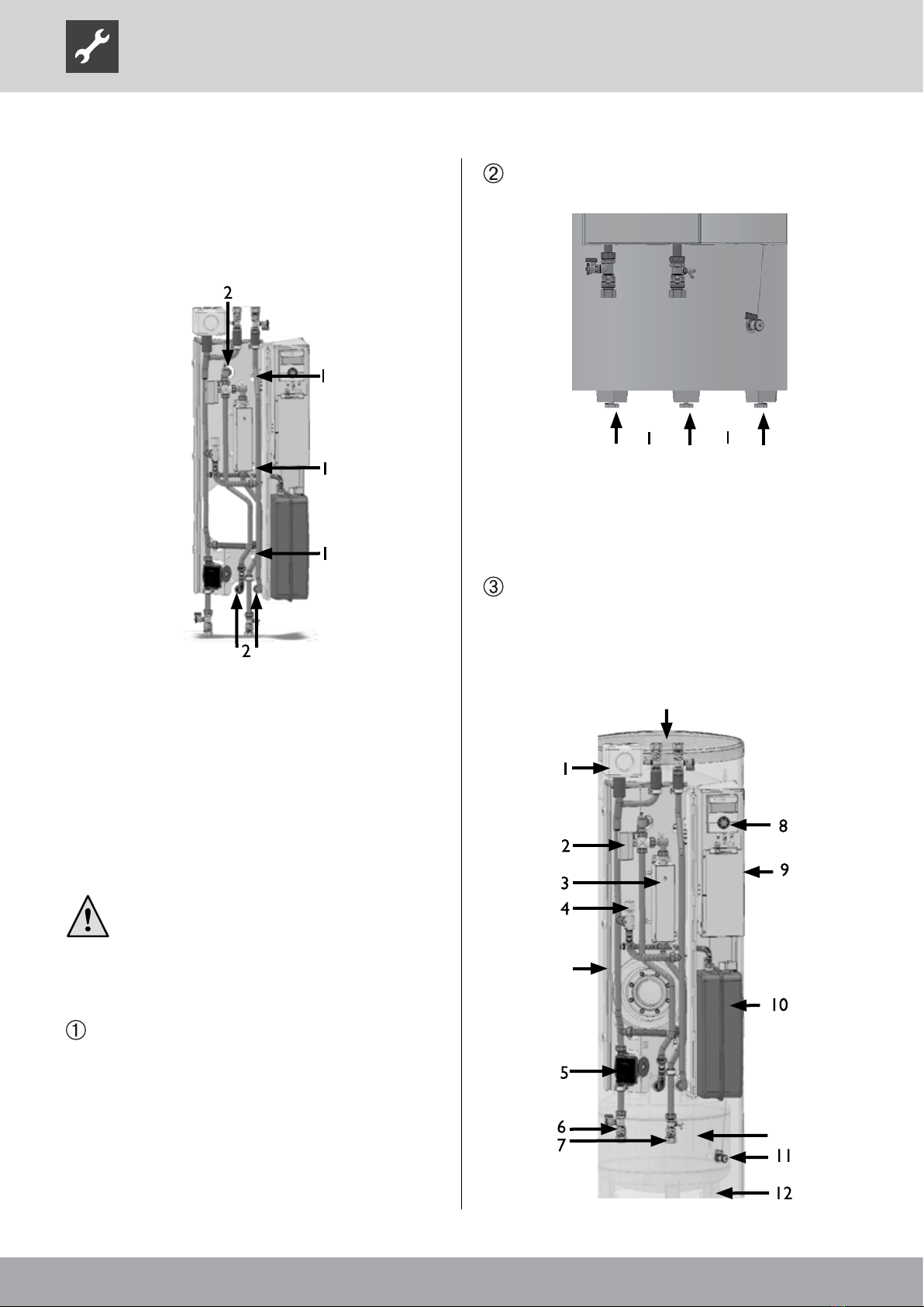
COMPONENTS OF THE UNIT
BWW
Galvanic anode
PSP

9
83053803dUK – Translation into English of the original German operating manual – Subject to change without notice. www.novelan.com
1 Heating circuit safety assembly (insulated)
2 Changeover valve, domestic hot water
3 Instantaneous water heater
behind heat shield
4 Overow valve
5 Circulating pump, heating circuit (HUP)
6 Shut-o ball valve with lling and drain cock
7 Shut-o ball valve with drain cock
8 Regulator
9 Switch cabinet
10 Expansion vessel
11 Drain, buer storage tank
12 Feet for adjustable screws
BWW Domestic hot water tank
PSP Buer tank
INSTALLATION / HYDRAULIC CONNECTION TO
HEATING CIRCUIT AND DOMESTIC HOT WATER
Connection positions for the heating circuit, the cold
and domestic hot water and for the circulation
see dimensioned drawings
NOTE.
Dimension heating system so that the free
compression of the circulating pumps integrated
in the unit always ensures the minimum heating
water throughput.
Always take into account the connecting lines
between the heat pump and the hydraulic
tower.
Remove the cover at the front of the Dual hydraulic
tower:
On the inside of the cover, on the left and right there are
3 grooves each, and on the tower housing the matching
3 pins on each side, which lock the cover in place:
It can therefore be taken apart and reassembled
manually.
IMPORTANT
When making the connections, always secure
the connections on the unit against twisting.
Flush heating circuit thoroughly before connecting
the unit to the heating circuit…
NOTE.
Contamination and deposits in the heating
circuit can cause malfunctions.
SAFETY COMPONENT
The safety assembly for the heating circuit is in the
enclosed pack of small parts.
Mount the safety assembly on the connection provided
on the top of the unit.
The safety drain of the safety valve must lead into
the drain via a funnel siphon in accordance with the
applicable standards and regulations!
EXPANSION VESSELS
The expansion vessel for the heating circuit is integrated.
Always check whether the size of the expansion vessel is
large enough for the system. If necessary, an additional
expansion vessel must be installed on site by the
customer according to the relevant standards.
NOTE.
The admission pressure of the expansion vessel
must be adjusted to the system (approx. 0.5 bar
less than the system lling pressure) according
to the calculation to the relevant standards (EN
12828).

10 83053803dUK – Translation into English of the original German operating manual – Subject to change without notice. www.novelan.com
NOTE.
All live wires must be stripped before they are
installed in the cable duct of the switch cabinet!
IMPORTANT
The power supply for the heat pump and the
electric heating element must be equipped with
an all-pole automatic circuit-breaker with at
least 3mm contact spacing to IEC 60947-2.
Note the level of the release current.
Overview “Technical data /scope of delivery”,
“Electrics” section..
The penetration for the electric and sensor cable is
located at the rear of the unit:
Open switch cabinet in unit.
To do this, only loosen the two upper screws of the
cover panel. Remove the remaining screws. Remove
cover panel.
Insert control and sensor wires and the wire for
the power company blocking contactor through
the bushings on the back of the unit. Guide wires
via the cable duct to the terminals in the switch
cabinet…
Make electrical connections as shown in the
terminal diagram…
“Terminal diagram” for respective unit type.
HYDRAULIC CONNECTION OF HOT WATER TANK
Connect hot water tank according to DIN 1988 and DIN
4753, Part 1 (or the local relevant standards, guidelines
and directives).
Do not exceed the operating pressures specied on the
rating plate. Install a pressure reducer, if necessary.
The sensor for the domestic water heating is already
wired up in the control cabinet.
IMPORTANT
The electrical conductivity of the domestic hot
water must be > 100µS/cm and lie within the
required drinking water quality.
DRAINING THE STORAGE TANK
IMPORTANT
Always ensure adequate ventilation when
draining the storage tank.
Electrical connections
The following applies to all work to be done:
DANGER!
Risk of fatal electric shock!
Electrical connection work must be carried
out by qualied electricians only.
Before opening the unit, disconnect the
system from the power supply and prevent it
from being switched back on!
WARNING!
During installation and while carrying out
electrical work, comply with the relevant
EN‑, VDE and/or local safety regulations.
Comply with technical connection
requirements of the responsible power
supply company (if required by the latter)!
11
83053803dUK – Translation into English of the original German operating manual – Subject to change without notice. www.novelan.com
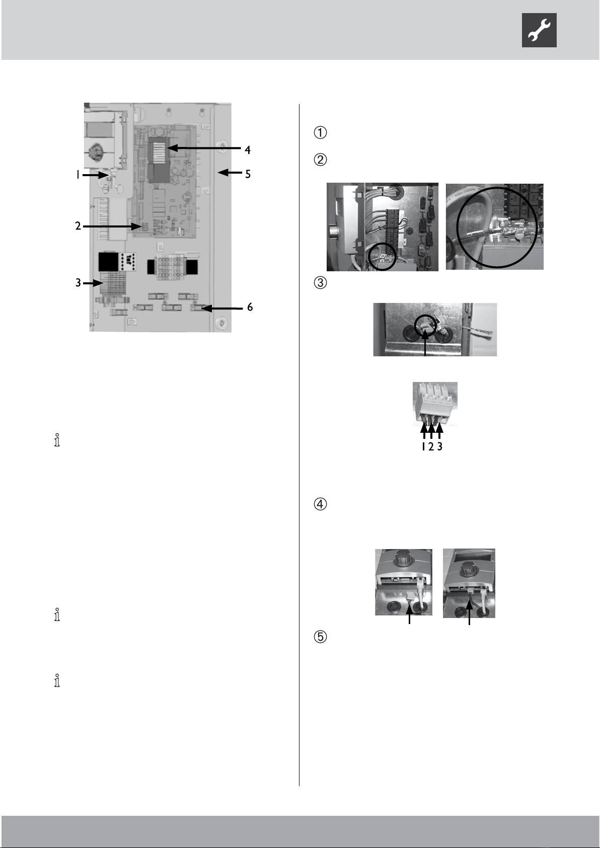
1 Bus cable connection
2 Terminal strip, external sensors
3 Control voltage connection
5 “Comfort” board
5 Electrical switch cabinet
6 Strain relief devices
NOTE.
The control unit of the heat and heat pump
regulator can be connected to a computer
or network using a suitable network cable,
enabling the heating and heat pump regulator
to be controlled remotely from there.
If such a connection is required, lay a shielded
network cable (category 6, with RJ-45
connector) through the unit during the electrical
connection work and connect it parallel to the
existing control cable of the heating and heat
pump regulator.
NOTE.
If an electric heating element is also installed in
the hot water tank, you must fuse it on site.
NOTE.
When laying the cable inside the building,
ensure that unshielded power supply cables
(outdoor unit voltage supply) and shielded
cables (LIN bus) are laid separately from each
other.
CONNECT BUS CABLE
Strip the BUS cable insulation and push the shield
back over the insulation.
Insert the end of the insulated cable with the shield
into the shield terminal.
Feed the end with the individual cores through one
of the two grommets.
Core assignment:
1 12 V
2 LIN
3 GND
Pull o the green bus connector from the bottom of
the control unit and connect the cable as shown in
the terminal diagram, then re-attach the connector
to the control unit.
After completing all electrical installation work,
lock the switch cabinet inside the unit. Close the
unit if no further installation work inside the unit is
to be carried out immediately.

12 83053803dUK – Translation into English of the original German operating manual – Subject to change without notice. www.novelan.com
Flushing, lling and venting the
system
IMPORTANT
The system must be absolutely free from air
before commissioning.
Dirt and deposits in the system can cause malfunctions.
FLUSHING, FILLING AND VENTING THE HEATING
CIRCUIT
IMPORTANT
Do not exceed a pressure of 2.5 bar when
ushing the unit. The drain line of the heating
circuit safety valve must be closed before
ushing and lling.
To ush the hot water heating circuit, dismantle
the motor of the 3-way valve. To do so, remove the
U-clip on the oor of the motor and carefully pull
o the motor from above....
Turn stem through 180° and ush domestic hot
water circuit for approx. 1 minute…
Turn stem through 180° back to starting position
(rounded side of stem points to B)…
Flush heating circuit! If necessary, the heating and
hot water circuit can be ushed at the same time!
To do so, turn spindle 30°...
After completion of the ushing and lling
procedure, move spindle to starting position and
mount the motor of the 3-way valve...
NOTE.
To ensure a good seat of the motor on the valve,
make sure that the U-clip with the waist is not
pushed past the lug, because then the motor
will not be held securely on the valve!
In order to be supported securely, the U-clip must bear
with both ends against the lug.
The unit is vented automatically when the venters
(black cap) are open. If the heating circuit is lled or
drained, the venting valves open.
Vent the exchanger of the hot water tank manually.
VENTING THE CIRCULATING PUMP OF THE
HEATING CIRCUIT
Loosen the screw-on cap in the middle of the circulating
pump for the heating circuit.

13
83053803dUK – Translation into English of the original German operating manual – Subject to change without notice. www.novelan.com
Set the overow valve
REMARQUE
The activities in this section are only necessary
for in-line tank integration.
Complete the worksteps quickly, otherwise the
maximum return temperature can be exceeded
and the heat pump switches to high-pressure
fault.
Turn the adjusting knob at the overow valve to
the right to increase the temperature dierence
(the temperature drop), turn it to the left to re-
duce it.
System is running in heating mode (ideally in cold
condition).
In case of low heating curve: Set the system to
“Forced heating”…
Operating manual of the heating and heat
pump controller.
Shut o valves to the heating circuit…
Ensure that the total ow is routed via the overow
valve…
Read out the ow and return temperature at the
heating and heat pump controller…
Operating manual of the heating and heat
pump controller.
Turn the adjusting knob (1) of the overow valve (2)
until the temperature drop between the ow and
return temperature is set as follows:
External temperature Recommended settings
-10 °C 4 K
0 °C 5 K
10 °C 8 K
20 °C 9 K
30 °C 10 K
Open valves to heating circuit…
Reset the heating and heat pump controller.
FLUSHING, FILLING AND VENTING THE DOMESTIC
HOT WATER TANK
IMPORTANT
Before ushing and lling the hot water
tank, the drain pipe of the safety valve must
be connected. Do not exceed the response
pressure of the safety valve.
Open domestic cold water inlet valve on domestic
hot water tank…
Open the domestic hot water valves at the taps…
Flush the domestic hot water tank until no more air
discharges from the valves at the taps…
Close hot water valves at the taps.
Insulating the hydraulic
connections
You must insulate the xed pipes of the heating circuit,
the connecting lines between the hydraulic tower and
the heat pump and the connections of the hot water
tank.
NOTE.
Insulate in accordance with relevant local
standards and directives.

14 83053803dUK – Translation into English of the original German operating manual – Subject to change without notice. www.novelan.com
Installation of the control unit
Remove the cover at the front of the Dual compact
station:
1 Four cutouts in the
switchroom panel
At the rear of the control unit there are 4 hooks, on
which the control unit panel is hung:
Press down the hung control unit, until it latches
into place…
Push the control cable of the heating and heat
pump regulator into the right‑hand socket on the
underside of the control unit…
Commissioning
Follow the instructions in the section entitled
“Commissioning” in the operating manual for
your heat pump.
Ensure that…
•the water supply to the domestic hot water tank
is open.
•the domestic hot water tank is lled.
If the heat pump is switched on with an empty
tank, the control unit will display a fault.
Operating manual of the heating and heat
pump regulator.
15
83053803dUK – Translation into English of the original German operating manual – Subject to change without notice. www.novelan.com
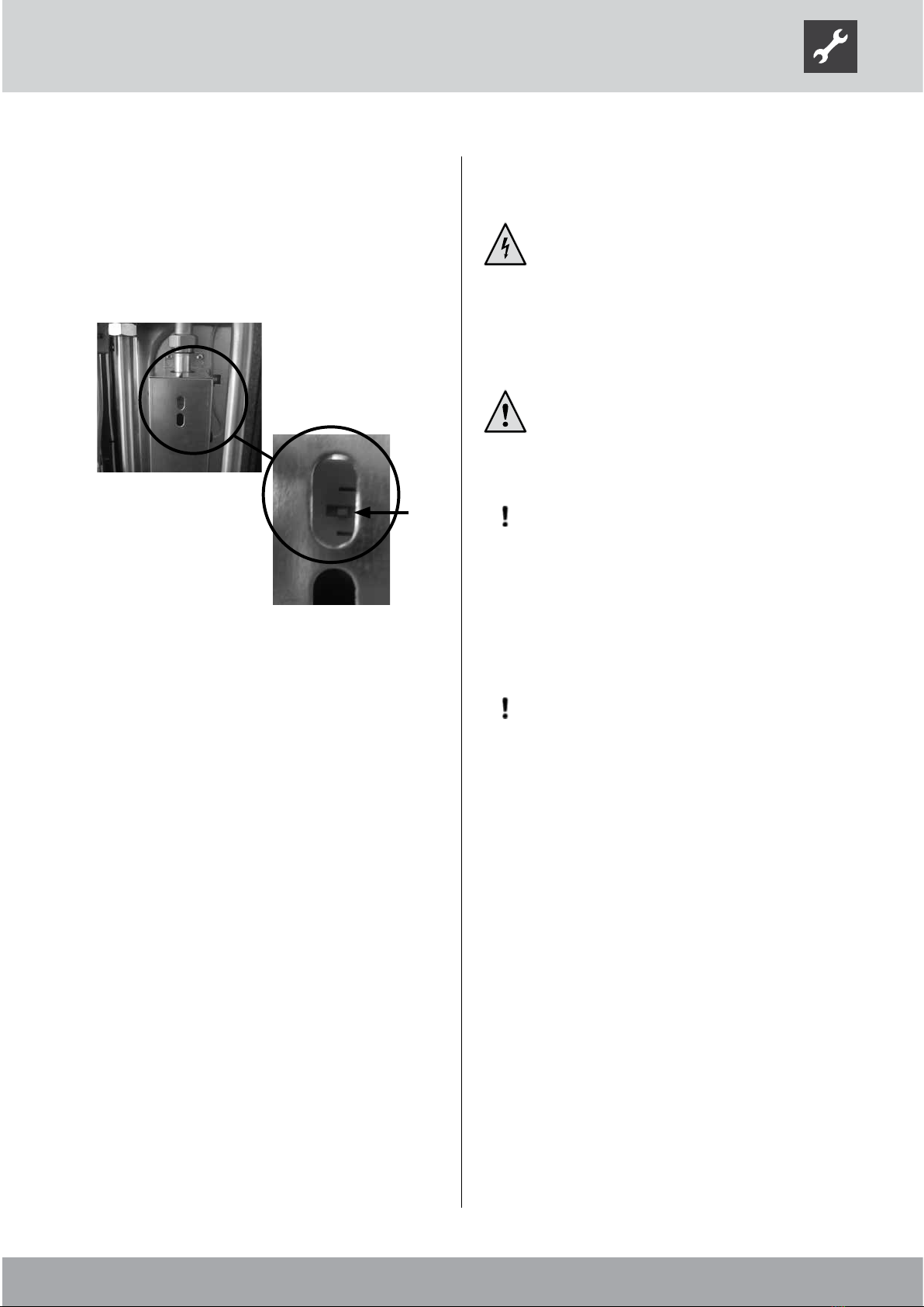
SAFETY TEMPERATURE LIMITER
A safety temperature limiter is built into the electric
heating element. In the event of a malfunction in the
heat pump or air in the system, check whether the reset
button of the safety temperature limiter has tripped. If
necessary push it in again (using an electrically insulated
screwdriver).
Safety temperature limiter and Reset button (arrow)
Dismantling
DANGER!
Risk of fatal electric shock!
Electrical connections may be installed only
by qualied electricians.
Before opening the unit, disconnect the
system from the power supply and prevent it
from being switched back on!
WARNING!
Only qualied heating or cooling system
personnel are allowed to dismantle the unit
from the system.
IMPORTANT
Recycle or ensure proper disposal of unit
components, refrigerants and oil according
to the relevant regulations, standards and
guidelines.
REMOVAL OF THE BUFFER BATTERY
IMPORTANT
Before scrapping the heating and heat pump
regulator, remove the buer battery on the
processor board. The battery can be pushed
out using a screwdriver. Dispose of battery and
electronic components in an environmentally
friendly way.

16 83053803dUK – Translation into English of the original German operating manual – Subject to change without notice. www.novelan.com
Unit designation
Accessory for heat pump
model LAD 5 - LAD 9 • applicable ı — not applicable
Functionally relevant • applicable ı — not applicable
Installation location Indoors ı Outdoors • applicable ı — not applicable
Conformity CE
Heating circuit Heating circuit efficiency pump integrated: • yes — no
Free compression heat pump ∆p ı Flow rate bar ı l/h
Flow rate: minimum throughout ı Maximum throughput l/h
max. permissible operating pressure bar
max. permissible operating temperature °C
Expansion vessel: Volume ı Normal inlet pressure l ı bar
Volume of buffer tank l
3-way valve, heating/hot water integrated: • yes — no
Heat metering integrated: • yes — no
Domestic hot water tank Net contents l
Corrosion protection: Impressed current anode ı Magnesium sacrificial anode • applicable ı — not applicable
Hot water temperature Up to °C
Output capacity at 38°C | 45 °C if removed at 10 l/min, storage temperature 60 °C l ı l
Output capacity at 38°C | 45 °C if removed at 10 l/min, storage temperature 50 °C** l ı l
Heat exchanger area, heat pump m²
max. permissible operating pressure bar
General unit data Housing dimensions (Height ı Width ı Depth) mm ı mm ı mm
Total weight kg
Connections Heating circuit ...
Heat pump
Cold water ...
Domestic hot water ...
Circulation ...
Electrics Voltage code ı all-pole circuit breaker heat pump *) ... ı A
Voltage code ı circuit breaker control voltage *) ... ı A
Voltage code ı circuit breaker electric heating element *) ... ı A
Protection type IP
Output, electric heating element 3 ı 2 ı 1 phase kW ı kW ı kW
Circulating pump, heating circuit: maximum power consumption ı current consumption kW ı A
Heating and heat pump
regulator Included in scope of delivery: • yes — no
Safety equipment Safety assembly heating circuit ı Safety assembly heat source Included in scope of delivery: • yes — no
Overflow valve integrated: • yes — no
Factory setting (adjust when commissioning the system) bar
Sound Sound pressure level in free field/sound power level dB(A) / dB(A)
* comply with local regulations ** Factory setting
Technical data/scope of delivery

17
83053803dUK – Translation into English of the original German operating manual – Subject to change without notice. www.novelan.com
CSD
•
•
• ı —
•
•
0,40 ı 1600
900 ı 2000
3
70
12 ı 1,5
62
•
•
180
— ı •
62
285 ı 230
215 ı 170
2,3
10
1800 ı 600 ı 834
150
Rp 1“ IG
Rp 1“ IG
R 1“ AG
R 1“ AG
R ¾“ AG
3~/N/PE/400V/50Hz ı C16
1~/N/PE/230V/50Hz ı B16
3~/N/PE/400V/50Hz ı B10
20
6 ı 4 ı 2
0,07 ı 0,31
•
• ı —
•
0,55
29 / 43
813309
18 83053803dUK – Translation into English of the original German operating manual – Subject to change without notice. www.novelan.com
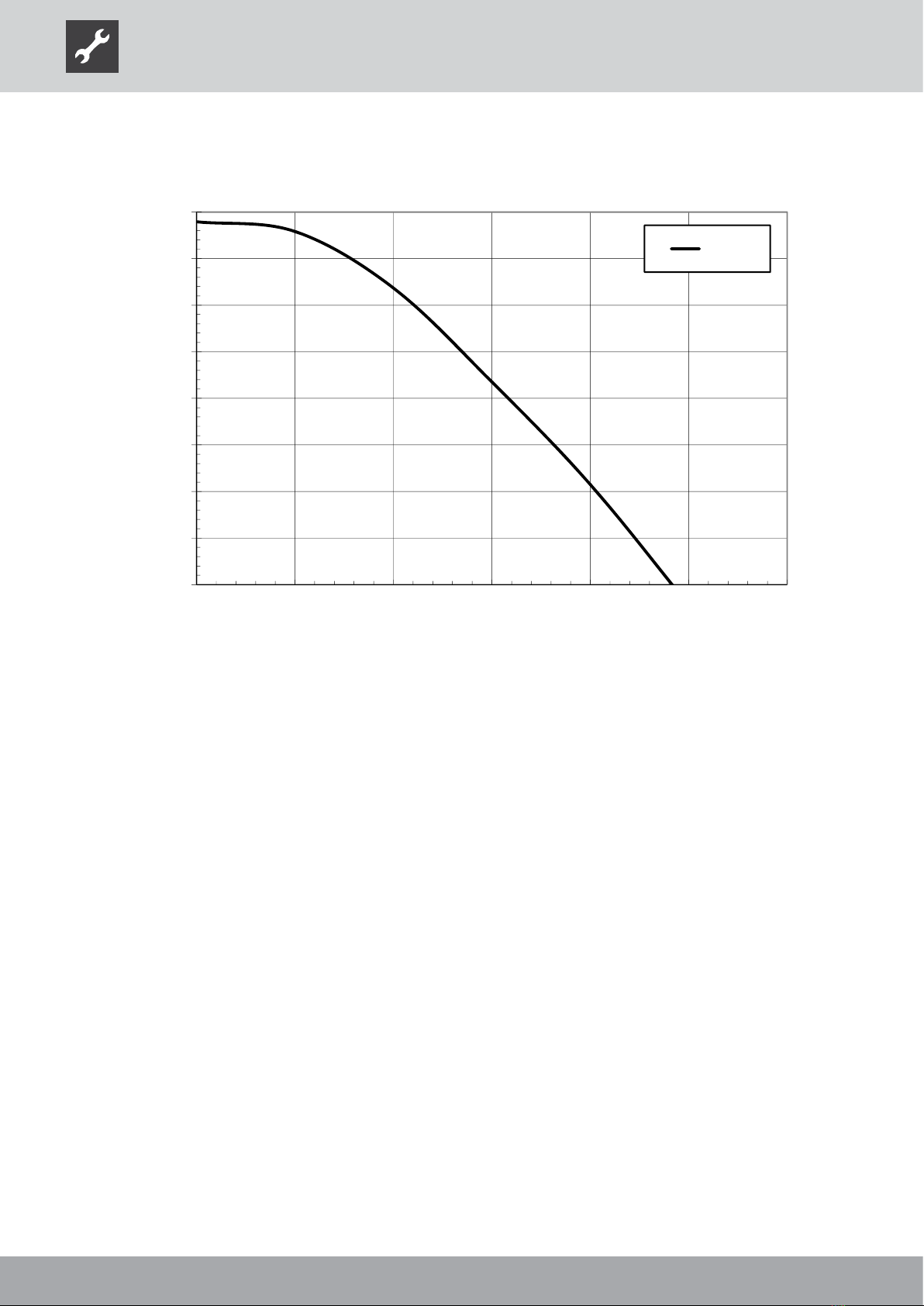
0,0
0,1
0,2
0,3
0,4
0,5
0,6
0,7
0,8
0,0 0,5 1,0 1,5 2,0 2,5 3,0
∆p (bar)
∆pmax
“ ” (m3/h)
Bezeichnung:
D t i 812032 F i P HTD(S)
812032
Seite: 1/1
Zeichnungsnummer:
Legende:
“ ” Volumenstrom Heizwasser in m3
/
h
∆pma
x
freie Pressung maximal (Werkseinstellung)
Freie Pressung HTD(S)
812032
Änd./ÄM/Ersteller/Datum
- /PEP 015-2011 / Liska / 21.06.2012
Legend: UK812022
“” Flow rate, heating water
∆p (bar) Free compression, heating circuit
Free compression Compact Station Dual

19
83053803dUK – Translation into English of the original German operating manual – Subject to change without notice. www.novelan.com
Compact Station Dual Dimensioned drawings
97
180 323
291
83
226
600
0
217
290
1547
<1800
2
3
1
5
67
4
639
0
649
599
834
30
300
0
547
1163
1651
508
216
11
8
9
10
A
E
B
8
7
6
5
4
3
2
1
www.alpha-innotec.de
D - 95359 Kasendorf
Industriestraße 3
Alpha-InnoTec GmbH
1
1
Ers. d.
Ers. f.
A
B
C
D
E
F
F
E
D
C
B
A
4
3
2
1
Benennung
Maßbild
Hydrauliktower Dual HTD 150713,-14
819417
-
Zust.
Änderungstext
PEP 015/2011
Datum
25.9.2012
RA
Von
Blatt
von
Werkstoff
Gewicht
Maßstab
1:20
Det. Maßstab
Datum
Name
Erstellt
Gepr.
Norm.
31.5.2012
Aepfelbach
25.9.2012
Aepfelbach
toleranz
Allgemein-
DIN ISO 2768 -c
Oberflächen
ArtikelNr.
Schutzvermerk ISO 16016 beachten
Legend: UK819417-
All dimensions in mm.
AFront view
BSide view from left
ERear view
Item Designation Dim.
1Safety assembly
2Heating water inflow (from heating circuit) Rp 1" IG
3Heating water outlet (in the heating circuit) Rp 1" IG
4Control unit
5Draining, buffer storage G 1/2"
6Heating water inflow (from heat pump) Rp 1" IG
7Heating water outflow (to heat pump) Rp 1" IG
8Domestic hot water R 1" AG
9Circulation R 3/4" AG
10 Cold water R 1" AG
11 Penetrations for electric/sensor cables
20 83053803dUK – Translation into English of the original German operating manual – Subject to change without notice. www.novelan.com
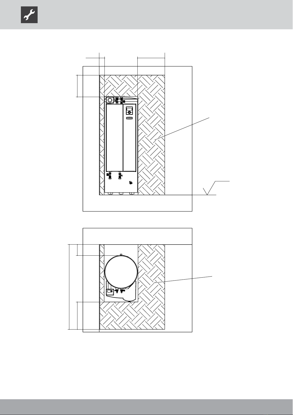
>100 >500
>1200
>400
FS
OKF
>1550
>500 >200
FS
Legende: 819418 -
Technische Änderungen vorbehalten.
Alle Maße in mm.
OKF Oberkante Fertigfussboden
FS Freiraum für Servicezwecke
8
7
6
5
4
3
2
1
www.alpha-innotec.de
D - 95359 Kasendorf
Industriestraße 3
Alpha-InnoTec GmbH
1
1
Ers. d.
Ers. f.
A
B
C
D
E
F
F
E
D
C
B
A
4
3
2
1
Benennung
Aufstellungsplan, Mindestabstände
Hydrauliktower Dual HTD
819418
-
Zust.
Änderungstext
PEP015/2011
Datum
14.6.2012
RA
Von
Blatt
von
Werkstoff
Gewicht
Maßstab
1:50
1:25
Det. Maßstab
Datum
Name
Erstellt
Gepr.
Norm.
5.6.2012
Aepfelbach
14.6.2012
Aepfelbach
toleranz
Allgemein-
DIN ISO 2768 -c
Oberflächen
ArtikelNr.
Schutzvermerk ISO 16016 beachten
Legend: UK819418
All dimensions in mm.
FFL Finished floor level
FS Shaded area = free space for service purposes
Installation plan Compact Station Dual
This manual suits for next models
1
Table of contents


