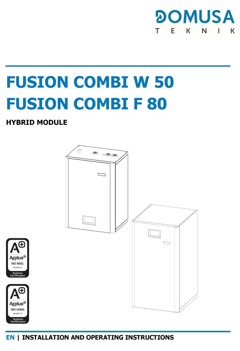
DOMUSA FUSION User manual

L INSTALLATION AND OPERATING INSTRUCTIONS
FUSION HE

Thank you for choosing a DOMUSA TEKNIK heat pump accessory. You have
chosen the FUSION model from the DOMUSA TEKNIK product line. This is an
all-in-one hydraulic accumulation module, which in combination with a heat
pump of the DUAL CLIMA line is able to provide the adequate level of comfort
for your home, provided that the hydraulic installationis correctly performed.
This document constitutes an essential part of the product and must be
delivered to the end user. Please carefully read the warnings and advice
contained in this manual, as they provide important information regarding the
safety of the installation, as wellas use and maintenance.
The installation of this appliance should be carried out only by qualified
personnel, in accordance with the regulations in force and following the
manufacturer’sinstructions.
Both the start-up and any maintenance operation of this appliance should be
carried out only by the Official Technical Assistance Services of DOMUSA
TEKNIK..
Incorrect installation of this product may cause damage to people, animals and
objects, for which the manufacturer shallnot be heldliable.

1
CONTENTS Page
1SAFETY WARNINGS......................................................................................................................................................................2
1.1USAGE AND INSTALLATION WARNINGS ................................................................................................................................................................2
1.2PERSONALSAFETYWARNINGS..............................................................................................................................................................................2
2LIST OF COMPONENTS...............................................................................................................................................................3
3INSTALLATION INSTRUCTIONS................................................................................................................................................4
3.1ACCESSORIESSUPPLIED........................................................................................................................................................................................4
3.2HYDRAULICINSTALLATION ...................................................................................................................................................................................4
3.3ASSEMBLYOF THE DHWPROBE...........................................................................................................................................................................5
3.4ASSEMBLY AND CONNECTION OF THE CONTROLPANEL ......................................................................................................................................6
3.5CONNECTINGTHEDHWDIVERTER VALVE (G1)..................................................................................................................................................7
3.6FILLINGTHE INSTALLATION...................................................................................................................................................................................8
3.7DRAINAGE .............................................................................................................................................................................................................8
4OPERATION.....................................................................................................................................................................................8
5OPTIONAL ACCESSORIES...........................................................................................................................................................9
5.1ASSEMBLY AND CONNECTION OF A BACKUP HEATER FOR DWH(E1)................................................................................................................9
5.2ASSEMBLY AND CONNECTION OF A BACKUP HEATER FOR HEATING (E2) ........................................................................................................10
5.3ASSEMBLY AND CONNECTION OFA BACKUP PUMP (C6)..................................................................................................................................11
5.4HEATING EXPANSION VESSEL.............................................................................................................................................................................12
6RECYCLING AND DISPOSAL....................................................................................................................................................13
7ELECTRICAL DIAGRAM..............................................................................................................................................................14
8DIAGRAMS AND MEASUREMENTS.......................................................................................................................................15
9SPARE PARTS LIST ......................................................................................................................................................................16

FUSION HE
2
1SAFETYWARNINGS
1.1 Usage and installationwarnings
The FUSION module should be installed by personnel authorised by the Ministry of Industry, in
compliance with the laws and regulations in force in the matter. The precautions detailed here
cover very important issues,so please be sure tofollow themaccordingly.
Please carefully read this instruction manual and keep it in a safe, easily-accessible place. DOMUSA
TEKNIK shall not be held liable for any damage that may occur due to failure to follow these
instructions.
The FUSIONstorage module can only be installed in combination with a heat pump from the DUAL
CLIMA line from DOMUSA TEKNIK. The FUSION module, in combination with a DUAL CLIMA heat
pump, is suitable for use in both heating and cooling installations, and can be combined with fan
coils, underfloor heating/cooling and low-temperature radiators. It should be connected to a
heating/cooling system and to a hot water distribution network that is compatible with its
performance and power.
This appliance should only be used for the purpose for which it has been expressly designed. Any
other use is considered unsuitable and therefore hazardous. The manufacturer shall not be
considered liable under any circumstances for damage caused by unsuitable, erroneous or
improperuse.
Remove all the packaging and check that the contents are complete. In case of doubt, do not use
the appliance and refer to the supplier. Keep the packaging elements out of reach of children, as
theycan bedangerous.
Improper installation or placement of equipment or accessories may cause electrocution, short
circuit, leakage, fire, or other damage to the equipment. Use only accessories or optional
equipment manufactured by DOMUSA TEKNIK and specifically designed to work with the products
presented in this manual. Do not modify, replace or disconnect any safety or control device without
first consulting the manufacturer or the Official Technical Assistance Service ofDOMUSA TEKNIK.
When it is decided not to use the equipment anymore, the parts likely to constitute potential
sourcesof dangershould be properlydecommissioned.
1.2 Personal safety warnings
Always wear suitable personal protection equipment (protective gloves, safety glasses, etc.) when
carrying out installation and/or maintenance operations in the unit.
Do not touch any switch with wet fingers. Touching a switch with wet fingers may cause electric
shock.Before accessingthe electrical components, fully disconnect the power supply.
Do not touch water pipes or internal parts during and immediately after operation. Pipes and
internalparts maybe excessively hotor cold,depending onthe use ofthe unit.
The hands may be burned by cold or heat in case of improperly touching pipes or internal parts. To
avoid injury, wait until the pipes and internal parts return to their normal temperature.
Alternatively, if access is required, be sureto wear appropriatesafety gloves.

3
2LIST OF COMPONENTS
1. DHW drain valve.
2. Dielectricsleeve.
3. Fillingdisconnector.
4. DHWexpansion vessel.
5. Controlpanel.
6. DHWtank.
7. DHW relief valve.
8. DHWsensor bulbsheath.
9. Manometer.
10. Connectionstrip.
11. Heating backup heater E2 (Optional).
12. DHW backup heater E1(Optional).
13. Installation backup pump C6(Optional).
14. Motorised3-way divertervalve.
15. Heatingexpansion vessel(Optional).
16. Waterfilter.
17. Installation drain valve.

FUSION HE
4
3INSTALLATIONINSTRUCTIONS
The FUSION hydraulic module can only be installed in combination with a heat pump from the DUAL
CLIMA line supplied by DOMUSA TEKNIK. Therefore, for their operation, these devices should be
connected to each other, both hydraulically and electrically. In this section, the necessary operations
forsaid connectionare described indetail.
3.1 AccessoriesSupplied
The following accessories are supplied inside the FUSION hydraulic module inside a
documentation bag. Before proceeding with the installation of the machine, make sure you receive
themand thatthey are ingood condition:
Documentation: Inside the machine, by opening the front, the documentation
bag can be located, including all the manuals and documents necessary for the
use and installation of theequipment.
Connection fitting Ø18x3/4”: Special fitting for the connection of the DHW
Domestic Cold Water inlet pipe (see
“Sketch and measurements”
). For its
correct use, please read carefully the section
“Hydraulicinstallation”
.
4x Connection fitting Ø22x1”: Special fitting for the connection of the pipes
with the Dual Clima heat pump and the Heating/Cooling Installation (see
“Diagrams and Measurements”
). For its correct use, please read carefully the
section
“Hydraulicinstallation”
.
3.2 Hydraulic installation
The hydraulic installation should be carried out by qualified personnel, in compliance with the
currentinstallation regulationand consideringthe followingrecommendations:
- All water circuit piping MUST be insulated to prevent condensation during operation in
cooling mode and reduction of cooling and heating capacity, as well as to prevent freezing of
outside pipes during winter. The minimum insulation thickness of the pipes should be 19 mm
(0.039 W/mK), preferably comprising a closed cell insulation or a vapor barrier. In outdoor areas
exposed to the sun, the insulation must be protected from the effects of degradation.
- It is advisable to insert shut-off valves between the installation and the hydraulic module, in
orderto simplifymaintenance work.
- Drain valves and suitable devices should be fitted for the correct removal of air from the circuit
duringthe fillingstage.
- The FUSION hydraulic module is an accessory that should be installed in combination with a
DUAL CLIMA heat pump for its correct operation. Therefore, in addition to the
recommendations described above, it must comply with those indicated in the heat pump
installation manual.

5
3.3 Assemblyof theDHW probe
For the correct functioning of the FUSION hydraulic module, the DHW probe, supplied in the DUAL
CLIMA heat pump, must be inserted in the bulb sheath provided in the module tank. This probe is
located inside the machine and is identified as “DHW TANK SENSOR”. For correct assembly, the
probe must be guided to where the FUSION module has been placed and inserted into the bulb
sheathprovided forit in thesame, followingthe steps indicatedbelow:
1.- Remove the access cover to the tank, located on
the roof of the module, by unscrewing the 4
fixingscrews andthe fasteningnut of the tank.
2.- Pass the bulb of the DHW temperature sensor
(“DHW TANK SENSOR") through the rubber
cableduct providedin the cover.
3.- Insert the sensor inside the bulb sheath
provided in the tank. Be sure to insert the sensor
bulb until it stops against the bottom of the
bulbsheath.
4.- Reassemble the access cover to the tank on the
roof of the module, tightening the 4 screws and
thefastening nut.
The probe supplied with the heat pump is 5 metres long. Where necessary, it can be extended up
toa maximumdistance of 50metres (sectionbetween 0.5÷1.25mm2).
IMPORTANT: When working on the electrical installation of the heat pump, make sure that it is
disconnectedfrom theelectrical network.

FUSION HE
6
3.4 Assemblyand connectionof the control panel
The control panel is supplied inside the heat pump and must be mounted on the front of the
FUSION hydraulic module. To do this, remove the front and access the electrical cabinet located at
the back. Forits correct assembly, pleasecarefully follow thefollowing steps:
1.- Loosenthe wingnuts indicatedin thefigure.
2.- Remove the support cap from the control panel, moving it
upwards.
3.- Removethe protectivefoam insert.
4.- Place the control panel removed from the DUAL CLIMA
heatpump inits place.
5.- Reassemble the control panel cover, inserting it into the
wingnuts, movingit downwards.
6.- Tighten the wing nuts to attach the handle to the drawer
unit.

7
Before switching on the heat pump, the control panel must be connected to the external machine.
To do this, pass the cable that is supplied inside the heat pump (located alongside the probe
harness) to the interior of the FUSION module. The hydraulic module has a series of cable ducts in
itsroof, throughone of whichit willbe possible tointroduce thecable inside theequipment.
Finally, the connectors of the cable and the control panel should be connected at their ends. A
cable with sufficient length should be provided inside the module, in such a manner that it is
possible to open the front of the equipment without having to disconnect said cable and facilitate
anymaintenance operationinside.
The cable supplied with the heat pump is 5 metres long. Where necessary, it can be extended up to
amaximum distanceof 100 metres(section between0.5÷1.25 mm2).
IMPORTANT: When working on the electrical installation of the heat pump, make sure that it is
disconnectedfrom theelectrical network.
IMPORTANT: Provide a sufficient length of cable inside the module in order to facilitate the
openingof thefront cover.
3.5 Connectingthe DHWdiverter valve (G1)
The FUSION hydraulic module includes a motorised 3-way diverter valve, which is responsible for
directing the flow of water from the heat pump to the DHW heat exchanger or to the
heating/cooling system, according to the command signal received from it. To do this, a 3-wire
electrical hose must be routed from the terminal strip of the DUAL CLIMA heat pump to the inside
of the FUSION module. The hydraulic module has a series of cable ducts in its roof, through one of
whichit willbe possible tointroduce thecable inside theequipment.
The electrical connection of the valve will be made between the general connection terminal of the
heat pump and the terminal strip of the FUSION module, by removing the cover to access it. The
following figures describe the form of connection of the motorised valve according to the heat
pumpversion available:
DUAL CLIMA Heatpump FUSION hydraulic module
IMPORTANT: When working on the electrical installation of the heat pump, make sure that it is
disconnectedfrom theelectrical network.

FUSION HE
8
3.6 Fillingthe installation
The FUSION hydraulic module has a filling disconnector and a manometer, by means of which the
water filling of the complete Heating/Cooling system can be carried out, including the external unit
and the exchanger of the DHW cylinder. In turn, the hydraulic installation should incorporate the
drainvalves andhydraulic components necessary for its correct filling.
To carry out the filling, open the disconnector valves until the
manometer indicates a pressure between 1 and 1.5 bar. The heat
pump (external unit) includes a manual drain valve on the upper
part of the heat exchanger flow tube (condenser). Open it during
the filling process and wait for the water to start running (please
refer to the operations manual of the DUAL CLIMA heat pump). The
air should also be bled from the rest of the installation using the air
bleed valves provided. The filling must be carried out slowly,
thereby facilitating air evacuation from the water circuit. Once the
installationis full,close the disconnectorvalves.
IMPORTANT: Starting the heat pump without water maycause serious damageto it.
3.7 Drainage
The FUSION hydraulic module has 2 drain valves: one to drain the
water from the primary installation and the other to drain the
Domestic Water from the inside of the tank. For the correct drainage
of any of the two circuits, a flexible tube should be connected to the
corresponding tube and led to a drain. In the case of the drainage of
the primary installation, it is advisable to open the steam traps
present in the heating/air conditioning system so that air enters the
circuit once the pressure in the circuit has been lost. After draining
the boiler, closethe valve again and remove the flexible tube.
4OPERATION
The FUSION hydraulic module is a passive accessory. Therefore, its operation will be fully managed by
the DUAL CLIMA heat pump controllers connected to it, which should be mounted on the front of the
module (see
“Assembly and connection of the control panel”
). To properly configure and manage its
operation, please carefully read the “Installation and Operating Instructions Manual” supplied
alongsidethe heatpump.
Nevertheless, in order to obtain all the features for which the all-in-one hydraulic module has been
provided, it should be ensured at least that the DHW service and the Heating and/or Cooling service
areactivated byadjusting theDIP-Switch (SW1) ofthe controlpanel of the heat pump.

9
5OPTIONAL ACCESSORIES
In order to complete the features offered by the FUSION hydraulic tank module, DOMUSA TEKNIK
offers a wide range of optional accessories that can be integrated inside it. The following sections
describe the correct assembly and connectionof theseaccessories.
5.1 Assemblyand connectionof a backupheater for DWH(E1)
The FUSION hydraulic module allows the assembly of a heating heater for DHW in the outlet
provided for this in the storage tank. With this heater, it will be possible to obtain Domestic Hot
Water production temperatures exceeding 50 ºC, enabling the necessary temperatures to be
reached for the correct execution of the function for protection against Legionella bacteria. For the
assembly, remove the socket cap and seal theheater onit:
1.- Disassemble and remove the plug from the socket
indicatedin thefigure.
2.- Assemble the heater supplied with the kit in its place,
makingsure toseal it correctly.
3.- Connect the power cable, supplied with the kit, to the Dual
Clima heat pump.
The electrical connection of the heater will be made between terminals E1L and E1N (neutral) of
the DUAL CLIMA heat pump components. To do this, an electrical hose (supplied in the DOMUSA
TEKNIK heater kit) should be carried from the FUSION module to the heat pump, located on the
outside. The hydraulic module has a series of cable ducts in its roof, through one of which it will be
possibleto removethe hose frominside theequipment.
The relay that activates the electrical heater has a maximum capacity of 20 A of consumption.
Therefore, to connect heaters exceeding 4,500 W, a contactor should be interposed between the
terminals of the powerterminal and the heater.
IMPORTANT: When working on the electrical installation of the heat pump, make sure that it is
disconnectedfrom theelectrical network.

FUSION HE
10
5.2 Assemblyand connectionof a backupheaterfor Heating(E2)
The FUSION hydraulic module allows the assembly of a heating element in the socket provided for
this purpose inside. With this heater, the required comfort features will be increased as required by
externalweather conditions.
For assembly, first cut the insulating shell that covers the socket cap, remove the plug, seal the
heater in place and, finally, coverthe heater cover with the previous shell:
1.- Cut the insulating shell that coversthe heater socket.
2.- Removethe insulatingshell.
3.- Disassemble and removethe 11/4” chrome cap.
4.- Assembleand sealthe heater inthe socket.
5.- Reassemble the insulation shell, making sure to cover the
heater cover correctly. Provide a hole in the shell to remove
thepower cable.
6.- Connect the power cable, supplied with the kit, to the Dual
Clima heat pump.
The electrical connection of the heater will be made between terminals E2L and E2N (neutral) of
the DUAL CLIMA heat pump components. To do this, an electrical hose (supplied in the DOMUSA
TEKNIK heater kit) should be carried from the FUSION module to the heat pump, located on the
outside. The hydraulic module has a series of cable ducts in its roof, through one of which it will be
possibleto removethe hose frominside theequipment.
The relay that activates the heater has a maximum capacity of 20 A of consumption. Therefore, to
connect heaters exceeding 4,500 kW, a contactor should be interposed between the terminals of
the power terminal and theheater.
IMPORTANT: When working on the electrical installation of the heat pump, make sure that it is
disconnectedfrom theelectrical network.

11
5.3 Assemblyand connectionof a backup pump (C6)
The FUSION hydraulic module allows the assembly of a circulation pump (C6) to increase the water
flow rate of the machine where necessary, in addition to that obtained by the internal pump of the
same (C4). Circulation pump C6 operates in parallel with the internal pump of the DUAL CLIMA
heatpump onlywhen it isoperating inHeating or Coolingmode.
For installation, a spool is installed in the return pipe of the heating/cooling system inside the
FUSION module for assembly of the optional pump offered by DOMUSA TEKNIK. To do this, first cut
the insulating shell that covers the spool, disassemble it and seal the
pumpin place:
1.- Cut the insulating shell covering the spool and remove it, as
indicatedin thefigure.
2.- Disassemblethe spooland remove it.
3.- Assemble the circulation pump in place, taking into
account the direction of flow indicated in the figure and
makingsure thatthe connections aresealed.
4.- Connect the power cable, supplied with the kit, to the Dual
Clima heat pump.
The electrical connection of the pump will be made between terminals C6L and C6N/N (neutral) of
the heat pump components. To do this, an electrical hose (supplied in the DOMUSA TEKNIK pump
kit) should be carried from the FUSION module to the heat pump, located on the outside. The
hydraulic module has a series of cable ducts in its roof, through one of which it will be possible to
removethe hosefrom inside theequipment.
IMPORTANT: When working on the electrical installation of the heat pump, make sure that it is
disconnectedfrom theelectrical network.

FUSION HE
12
5.4 Heatingexpansion vessel
The DUAL CLIMA heat pump incorporates an expansion vessel with capacity for 2 litres by default.
In the event that it is necessary to increase this capacity, due to the total amount of water in the
Heating/Cooling system, the FUSION hydraulic module allows the installation of an 8-litre
expansionvessel kit(optionally supplied)insideit.
For its correct assembly inside the FUSION module, once it is ensured that the heating/cooling
system is empty,please carefully followthe stepsindicated inthe following figures:
1.- Cut the insulation to access the plug of the expansion
vessel socket, located above the water filter (see
“List of
components”)
. Cu the area in such a manner that the
removed insulation can be reused.
2.- Disassemble the cap from the expansionvessel socket.
3.- Place the expansion vessel under the base of the bottom
right of the module, as indicated in the figure, with the
socket facing towards the front and upwards.
4.- Fix the expansion vessel to the base of the module, using
the support plate and the screws supplied with the kit, as
indicatedin thefigure.
5.- Connect the expansion vessel and the socket provided in
the module, using the hose supplied with the kit, making
sureto sealboth ends of the connectioncorrectly.
6.- Replace the insulation around the entire area where it was
previously removed, making sure to cover all the
componentsexposed to possiblecondensation.
IMPORTANT: Before proceeding with the assembly of the expansion vessel kit inside the
module,make surethat the Heating/Coolingsystem isempty.

13
6RECYCLING AND DISPOSAL
Uninstallation
This product should be uninstalled byauthorised personnel for the handlingof fluorinatedgases.
The heat pump contains R410A refrigerant. Any leakage of refrigerant into the atmosphere should
beavoided.
Recycling
For recycling or disposal, the heat pump must be taken to a waste collection point. Contact
qualified personnel for the handling of fluorinated gases. Contact the installer or the local authority
for more information.
Disposal
Donot attemptto uninstall thisproduct onyour own.
Theuninstallation andtreatment of the refrigerant, oil and other components should becarried out
in accordance with the local and national legislation. The complete equipment, including the
compressor and the oil contained, should be disposed of at a waste collection point, as it may
contain refrigerant waste.
Allrefrigerant shouldbe removedand returnedto themanufacturer for recyclingor disposal.

FUSION HE
14
7ELECTRICALDIAGRAM
V3V: 3-way reversing valve.
R: Relay.
G1C/L: Heat Pump DHW signal (NC).
G1O/S: Heat Pump Heating signal (NO).
G1N/N: Heat Pumpcommon signal(Neutral).

15
8DIAGRAMSAND MEASUREMENTS
Frontview Top view
FUSION HE 150
(mm) FUSION HE 200
(mm) FUSION HE 300
(mm)
Total height A 1560 1965 1995
Rack height B 1475 1880 1910
Bottom C 600 600 650
IBC D
485 485 490
IBC E
390 390 375
IC: Heating/CoolingFlow, Ø22(fitting 1” M).
RC: Heating/CoolingReturn, Ø22 (fitting1” M).
IBC: HeatPump Flow,Ø22 (fitting 1”M).
RBC: HeatPump Return,Ø22 (fitting 1”M).
ACS: DomesticHot WaterOutlet, 1/2” M.
AFS: DomesticCold Water Inlet,Ø18 (fitting 3/4”M).
R: DHWRecirculation Socket,1/2” M.
VS: DHW SafetyValve,1/2” F.

FUSION HE
16
9SPAREPARTS LIST
Jackets
1
3
5
8
10111213
17
19
15
2
4
6
6
7
914166
6
18
21 22
6
20

17
N. Code Name
1 SEXT000498 FRONTJACKET FUSION HE 150
SEXT000553 FRONTJACKET FUSION HE 200
SEXT000560 FRONTJACKET FUSION HE 300
2 SEXT000646 FUSIONBOARDTRIM
3 SELEDCL000 FUSIONMAINBOARD
4 CTOR000040 ZINC-PLATEDROUND-HEADED SCREW PHILLIPDIN-7985M5x10
5 SEPO003057 ELECTRICALBOARD COVER
6 CTOR000073 ZINC-PLATEDSHEET METAL ROUND-HEADEDSCREWPHILLIPWITH
RIBBEDWASHER3.9x9.5
7 SELEDCL001 ELECTRICALSHEETFUSION
8 SEXT000447 RIGHTSIDEJACKETFUSION HE 150
SEXT000455 RIGHTSIDEJACKETFUSION HE 200
SEXT000462 RIGHTSIDEJACKETFUSION HE 300
9 SEXT000449 TOPJACKET FUSION HE 150/200
SEXT000853 TOPJACKETFUSIONHE300
10 CFER000083 CABLE GROMMET SR1707 110539
11 CFER000314 PIPE PLASTICTRIM,WHITEØ22
12 SEPO003016 ACCESSCOVER
13 SEPO003063 TOPCOVER WASHER
14 CTOR000092 ZINC-PLATEDHEX-NUT DIN-934M8
15 CFER000187 CABLE GROMMET A0113 FOR Ø12
16 CFER000138 WHITECAP Ø10.75 PGO-126/10
17 SEPO003014 BACK JACKET FUSIONHE 150
SEPO003022 BACK JACKET FUSIONHE 200
SEPO003025 BACK JACKET FUSIONHE 300
18 CTOR000198 TRILOBULARTHREAD FORMING SCREW PHILIPSHEADM5x10
19 SEXT000446 LEFTSIDEJACKETFUSIONHE150
SEXT000454 LEFTSIDEJACKETFUSIONHE200
SEXT000463 LEFTSIDEJACKETFUSIONHE300
20 CFER000261 SRV LATCH SPRING
21 CTOE000355 LATCH PIN
22 CTOR000089 ZINC-PLATEDHEX-NUT WITH WASHER DIN-6923M4

FUSION HE
18
Mainboard
2356 14
N. Code Name
1 SCON002098 BOARD SUB-UNIT
2 SOPE000084 PAINTEDEVOLUTIONRC PUSH-BUTTON
3 SCHA012936 ELECTRICAL BOX
4 CTOR000089 ZINC-PLATEDHEX-NUTWITH WASHER DIN-6923
M4
5 SCHA013293 SUPPORTCOVER
6 CTOR000306 ZINC-PLATED WING NUT M4
Table of contents