NU CRTN836 User manual

Operator's Manual Ride-On Power Trowel
CRTN836 | CRTS836 & CRTN846
Unit 2 Low Farm Low Road, Morley St Botolph, Wymondham, United Kingdom, NR18 9BU
01953 711952
www.nuequipment.co.uk

2
Original instructions This Operator’s Manual presents the original instructions. The original
language of the Operator’s Manual is English.

3
Foreword
This manual contains important instructions for this machine. These instructions must be
followed during installation, operation, and maintenance of the machines.
This manual provides information and procedures to safely operate. For your own safety and to
reduce the risk of injury, carefully read, understand, and observe all instructions described in this
manual.
We reserves the right to change any of the contents in this manual without notice.
Warranty
Our products are covered by warranty for a period of twelve (12) months from the date of
purchase against defects in material or workmanship provided that:
The product concerned has been operated and maintained in accordance with the
operating instructions.
Has not been damaged by accident, misuse or abuse.
Has not been tampered with or repaired by any unauthorized person.
Any evidence of failure to meet these conditions may result in a denial of the warranty claim.
The owner is responsible for the cost of transportation to and from the authorized repairer and
the unit is at the owners risk while in transit to and from the repairer.
Impact damage is not covered under warranty. Clutches are not covered under any warranty.
Engines are officially guaranteed by engine manufacturer. Please refer to the annex for engine
warranty.

4
Table of Contents
Foreword 3
Warranty 3
1. SAFETY INFORMATION.………………………………………………………………….. .5
1.1 Operating Safety………………………………………………………………………….....5
1.2 Operator Safety while using Internal Combustion Engines……………………………..6
1.3 Label Locations………………………………………………………………………………7
1.4 Safety and Operating Labels……………………………….…………………………….8-9
2. OPERATION …………………………………………………………….……………………... 10
2.1 Control…………………………………………………………………………………….…….10-11
2.2 Preparing the Machine for First Use …………………………………………………...….……12
2.3 Before Starting……………………………………………………..………………….…………..12
2.4 To Start …………………………………………………………………………………………….12
2.5 To Stop ……………………………………………………………….………………….....…….. 13
2.6 Operation………………………………………………………………………………….…..13
2.7 Steering…………………………………………………………………..…………………...13
2.8 Pitch Adjustment…………………………………………………………………………...…13
3. MAITENANCE ……………………..………………………………………………...…..……. 14
3.1 Periodic Maintenance Schedule………………………………………..………………..…14
3.2 Trowel Gearbox………………………………………………………………..…..…………14
3.3 Lubrication…………………………………………………………………………..…..…….15
3.4 Transporting Trowels…………………………………………………………………......……....15
3.5 Trouble Shooting ………………………………………………………………………………….16
4. TECHNICAL DATA ………………………...……………………………………..……… 17-18
EC DECLARATION OF CONFORMITY ………………………………..……………19

5
1. SAFETY INFORMATION
1.1 Operating Safety
Only trained personnel are permitted to start, operate, and shut down the machine.
They have received instruction on how to properly use the machine and are familiar
with required safety devices
The machine must not be accessed or operated by children and people impaired by
alcohol or drugs.
NEVER operate this machine in application for which it is not intended.
NEVER allow anyone to operate this equipment without proper training. People
operating this equipment must be familiar with the risks and hazards associated with
it.
NEVER operate the machine with the beltguard missing. Exposed drive belt and
pulleys create potentially dangerous hazards that can cause serious injuries.
DO NOT allow anyone to stank or lean on the unit during operation.
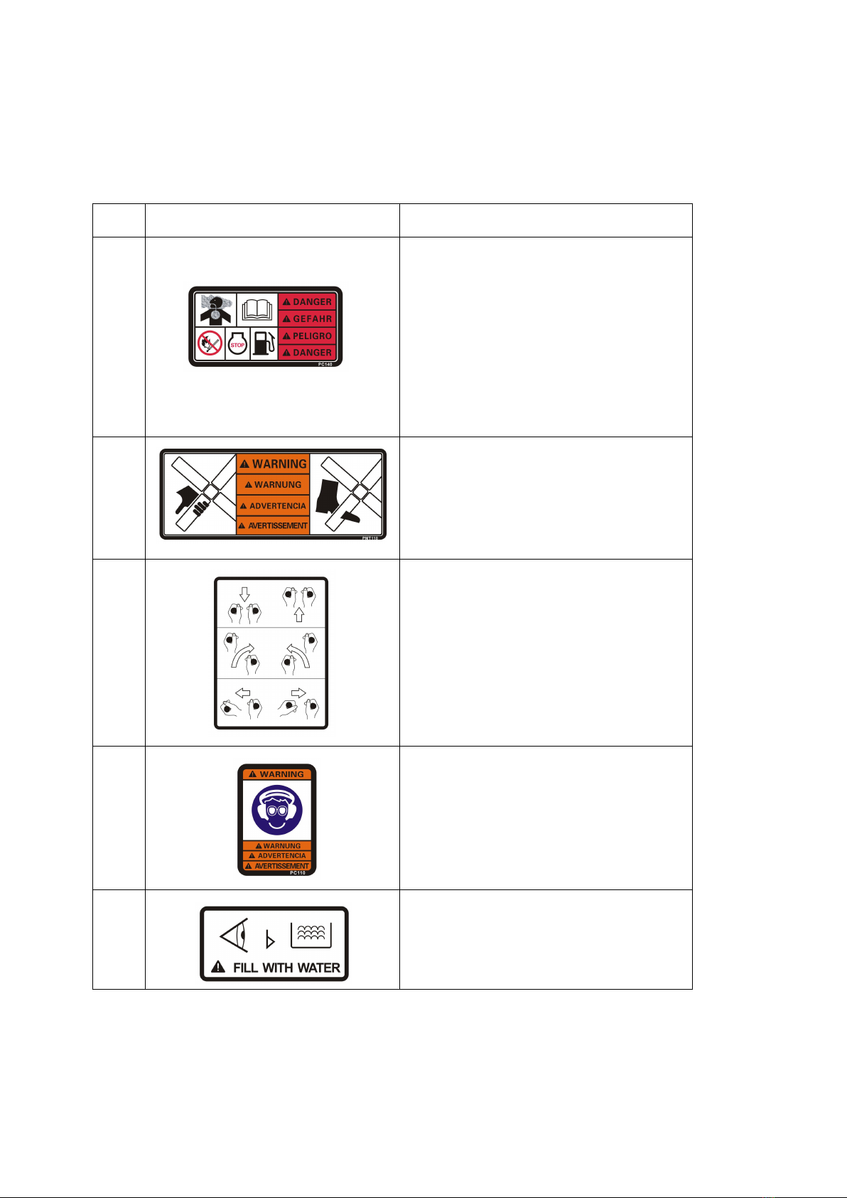
Do not run the machine indoors or in an enclosed area such as a deep trench unless
adequate ventilation, through such items as exhaust fans or hoses, is provided.
Engine exhaust contains carbon monoxide. This is a poison you cannot see or smell.
Exposure to carbon monoxide can cause loss of consciousness and CAN KILL YOU
IN MINUTES.
Do not operate the machine with unapproved accessories or attachments.
ALWAYS Keep the safety stop switch system in adjustment and good operating
condition at all times. Do not operate the trowel if it does not work properly. Out of
control Trowels can cause serious personal injury and damage to fresh concrete
surfaces. This system will automatically stop the unit if the operator loses control of it
during operation.
ALWAYS make sure the safety stop switch is disengaged (lever in the down position)
before starting the unit. Keep one hand firmly on the handle while starting and do not
let go of the handle during operation.
ALWAYS wear protective clothing appropriate to the job site when operating the
machine.
ALWAYS close fuel valve on engines equipped with one when machine is not being
operated.
ALWAYS store the machine properly when it is not being used. The machine should
be stored in a clean, dry location out of the reach of children.
Read, understand, and follow procedures in the Operator’s Manual before attempting
to operate the machine.

6
1.2 Operator Safety while using Internal Combustion Engines
DO NOT smoke when refueling the engine or during any other fuel handling
operation.
DO NOT refuel a hot or running engine.
DO NOT refuel the engine near an open flame.
DO NOT spill fuel when refueling the engine.
Do not touch the engine or muffler while the engine is on or immediately after it has
been turned off. These areas get hot and may cause burns.
If fuel is spilled during refueling, wipe it off from the engine immediately and discard
the rag in a safe place. Do not operate the unit if fuel or oil leaks exist-repair
immediately.
NEVER operate this equipment in an explosive atmosphere.
NEVER operate any gas powered equipment in a poorly ventilated or enclosed area.
NEVER perform any work on the unit while it is running. Before working on it, stop
the engine and disconnect the spark plug wire to prevent accidental starting.
Avoid prolonged breathing of exhaust gases.
Avoid contact with hot exhaust systems and engine parts.
Allow engine to cool before performing any repairs or service.
ALWAYS transport and handle fuel only when contained in approved safety
containers.
ALWAYS keep the area around the muffler free of debris such as leaves, paper,
cartons, etc. A hot muffler could ignite the debris and start a fire.

7
1.3 Label Location

8
1.4 Safety and Operating Labels
CONMEC machines use international pictorial labels where needed. These labels are
described below:
Ref.
Label
Meaning
A
DANGER!
Engines emit carbon monoxide; operate
only in well-ventilated area. Read the
Operation Manual for machine
information. No sparks, flames, or
burning objects near the machine. Shut
off the engine before refueling. Use only
clean, filtered unleaded gasoline.
B
WARNING!
Cutting hazard. Always replace blade
guard!
C
Steering control. Refer to section
Steering.
D
WARNING!
Always wear hearing and eye protection
when operating this machine.
E
Water tank fill. Use only clean water or
water-based retardants.

9
Ref.
Label
Meaning
F
CAUTION!
Check the fuel. Use only clean,
filtered gasoline fuel.
G
WARNING!
Hand injury if caught in moving belt.
Always replace belt guard.
H
CAUTION!
Tie-down point.
I
Key switch, engine start:
Off
On
Start
J
WARNING!
Hot surface!
K
WARNING!
Read and understand the supplied
Operator’s Manual before operating
the machine. Failure to do so increase
the risk of injury to yourself or others.
A nameplate listing the model number
and serial number is attached to each
unit. Please record the information
found on this plate so it will be
available if the nameplate lost or
damaged. When requesting service
information, the serial number should
be specified of the unit.

10
2. OPERATION
2.1 Controls

11
Ref. No.
Description
Ref. No.
Description
1
Machine Frame
9
Engine
2
Operator’s Seat Bottom
10
Engine Mounted Plate
3
Right Gearbox Assy.
11
Belt Guard
4
Right Trowel Arm Assy.
12
Guard Ring
5
Chain Bottom
13
Clutch
6
Left Gearbox Assy.
14
Belt
7
Left Trowel Arm Assy.
15
Sprinkle System
8
Guard Ring

12
2.2 Preparing the Machine for First Use
2.2.1 Make sure all loose packaging materials have been removed from the
Machine.
2.2.2 Check the machine and its components for damage. If there is visible
damage, do not operate the machine! Contact our dealer immediately for assistance.
2.2.3 Take inventory of all items included with the machine and verify that
all loose components and fasteners are accounted for.
2.2.4 Attach component parts not already attached.
2.2.5 Add fluids as needed and applicable, including fuel, engine oil, and
battery acid.
2.2.6 Move the machine to its operating location.
2.3 Before Starting
New Ride-on Power Trowel has been assembled and tested at the factory. However, before
starting the trowel, the following items should be checked:
Fuel level
Water level
Oil level in the engine
Condition of the air filter
Condition of trowel arms and blades
Grease the trowel arms daily.
NOTICE: Check the oil level in the engine and gearbox. Engine and trowel warranties are VOID if
this unit is run without oil.
2.4 To Start
Before starting the operator must know the location and function of all controls.
1. Adjust the chair to the comfortable position for the operator.
2. Push down on the left safety stop pedal, turn the engine keyswitch, and hold it until the engine
starts.
NOTICE: If the engine is cold, pull out the choke control knob fully. The choke may need to be
opened even when starting a warm engine.
NOTICE: Cranking the engine for more than 5 seconds can cause starter damager. If the
engine fails to start, release the keyswitch and wait 10 seconds before operating the starter
again.
3. Allow the engine to warm up before operating the trowel.
4. Push down on the throttle foot pedal to start the trowel

13
2.5 To Stop
1. Return the control levers to their neutral position and release pressure on the throttle foot
pedal.
2. Release pressure on the safety stop switch.
3. To stop the engine, turn the keyswitch to “O” (off).
NOTICE: Release the safety stop switch for emergency stop.
2.6 Operation
To utilize your Ride-On Trowel to its fullest capacity, the machine should be driven in the
direction that the operator is facing. This will finish the widest possible area, while giving the
operator and excellent view of the slab surface about to be troweled. When the machine
reaches the end of the slab, make a 180°U-turn, and repeat the straight line of direction to
the other end of the slab.
NOTICE: DO NOT use excessive pressure on the control levers. Excessive pressure does
not increase the reaction time of the machine and can damage the steering controls.
NOTICE: Attempting to use the trowel too early in the curing stage of the concrete may result
in an undesirable finish. Only experienced concrete finishers should operate the trowel.
2.7 Steering
The moving direction Control:
1. Reverse: Pull the control arm reverse
2. Forward: Push the control arms forward
3. rotate clockwise: Push the left control arm forward, pull the right control arm reverse.
4. rotate counter-clockwise: Push the right control arm forward, pull the left control arm
reverse.
5. left sideways: Turn the left control arm left.
6. right sideways: Turn the right control arm right.
2.8 Pitch Adjustment
When changing or setting the pitch (angle) of the trowel blades, slow the machine, set the
desired pitch on the left side of the machine, then adjust the right side to match.
To increase the pitch, turn the pitch control inward.

14
3 MAINTENANCE
3.1 Periodic Maintenance Schedule
The chart below lists basic trowel and engine maintenance. Refer to engine manufacturer’s
Operator's Manual for additional information on engine maintenance. A copy of the engine
Operator's Manual was supplied with the machine when it was shipped. To service the
engine, tilt the seat forward.
Daily
Every
20
hours
Every
50
hours
Every
100
hours
Every
200
hours
Every
300
hours
Grease trowel arms.
Check fuel level.
Check engine oil level.
Inspect air filter. Replace as needed.
Check external hardware.
Pressure wash all surfaces until free
of concrete.
Check oil level in gearboxes.
Grease gearbox, drive system and
pitch posts fittings.
Grease control linkage.
Check drive belt for wear.
Change engine oil.
Check fuel filter.
Clean and check spark plug.
Replace oil filter.
Replace spark plug.
Replace fuel filter.
Replace gearbox pressure relief valve.
Replace oil in gearboxes.
3.2 Trowel Gearbox
Check the gearboxes for the correct oil level after every 20 hours of operation. Change the
gearbox oil every 300 hours.
NOTICE: DO NOT mix types of gear oil. DO NOT overfill the gearbox with oil. Damage to the
gearbox may occur if oils are mixed, or if the gearbox is overfilled. See Technical Data for oil
quantity and type.

15
3.3 Lubrication
1. Engine oil
The long life and successful operation of any piece of machinery is dependent on frequent
and thorough lubrication
Before using the trowel, always check your engine for oil. Use proper engine oil as
recommended in the engine manufacturer’s manual. Fill crankcase to levels as
recommended.
2. Trowel
The drive system, gearbox and pitch posts are equipped with several grease fittings. Grease
these fittings once a week, or every 20 hours, to prevent wear.
Use a general purpose grease and add one to two shots of grease at each fitting.
3.4 Transporting Trowels
ALWAYS turn the engine off and remove the key from the machine before moving or
transporting machine.
To hoist the trowel:
1. Attach a sling or chains through the tie-down point (a) on each side of the guard ring.
NOTICE: Make sure lifting device has enough capacity to hold machine (see identification
plate on machine for weight).
2. Use the trolley wheel for transportation.

16
3.5 Trouble Shooting
SYMPTOM
POSSIBLE CAUSES
SOLUTION
Engine does not start.
Engine problem.
Consult engine manufacturer’s
service manual.
Machine out of
balance; wobbling
excessively.
Operator is over-steering.
Trowel arm(s) bent.
Trowel blade(s) bent.
Main shaft(s) bent due to
machine being dropped.
The movement of each gearbox
is controlled by “stops” to provide
the correct relationship of the
control arm movement to
machine movement. Excessive
pressure on control arms in any
direction will not increase
reaction time and can damage
steering controls causing
machine to wobble.
Replace trowel arms(s).
Replace trowel blade(s).
Replace main shaft(s).
Machine does not
move.
Drive belt broken.
Vacuum between bottom of
blades and surface of
concrete.
Key sheared in the main
shaft.
Replace drive belt.
Change pitch on blades to break
suction.
Replace damaged key.
Trowel noisy.
Trowel blades have
become misaligned and
are contacting each other
during rotation.
Sheared key.
Loose clutch.
Replace damaged blades. Align
blades so that one set
represents a (+) and the other an
(x) when viewed from above.
Check all keys in drive system.
Tighten clutch.

17
4. TECHNICAL DATA
Model
CRTS836-2/
CRTN836-2
CRTS836-4/
CRTN836-4
Engine type
Chinese
Petrol Engine
Honda GX690
Power
kw(hp)
13.4(17.8)
16.5 (22.1)
Operating weight
kg(lb)
339(746)
359(790)
340(748)
360(792)
Blade speed
rpm
70-150
Working Dia.
mm
1910
Blade pitch (range)
degree
0-15
Overlapping
type
Non-overlapping
Gearbox Lubrication
type/ml
Glygoyle / 1300
Model
CRTN846-5
CRTN846-980
Engine type
B&S Vanguard
Kohler CH980
Power
kw(hp)
26.1 (35)
28.3(38)
Operating weight
kg(lb)
436 (959)
436 (959)
Blade speed
rpm
70-150
Working Dia.
mm
2350
Blade pitch (range)
degree
0-15
Overlapping
type
Non-overlapping
Gearbox Lubrication
type/ml
Glygoyle / 1300
Working Size (L x W x H):
CRT836: 2019mm x 1050mm x 1200mm
CRT846: 2420mm x 1160mm x 1250mm
Engine type may vary, please see listing

18
Sound Specification
The required sound specification:
CRT836 Series
CRT846 Series
The sound pressure level at operator’s location (LpA)
89dB(A)
91dB(A)
The guaranteed sound power level (LWA)
110dB(A)
112dB(A)
These sound values were determined according to ISO 3744 for the sound power level (LWA)
and ISO 11204 for the sound pressure level (LpA) at the operator’s location.
Vibration Specification
The weighted effective acceleration value, determined according to ISO 2361-1 and ISO 5349,
is:
CRT836 Series
CRT846 Series
for whole body:
0.22 m/s2
1.46m/s2
for hand arm:
1.81 m/s2
2.95 m/s2
The sound and vibration specifications were obtained with the unit operating on fully cured,
water wetted concrete at nominal engine.

Unit 2 Low Farm Low Road, Morley St Botolph, Wymondham, United Kingdom, NR18 9BU
01953 711952
www.nuequipment.co.uk
Version: 202207-04
This manual suits for next models
2
Table of contents
Other NU Trowel manuals
Popular Trowel manuals by other brands

Sima
Sima HALCON 90 Original user guide

Husqvarna
Husqvarna BG 245E Operator's manual

MBW
MBW F36 Operator's safety and service manual

MULTIQUIP
MULTIQUIP Standard Handle SXH Assembly & installation

allen
allen MSP455 Safety & operation manual

Marshalltown
Marshalltown Shockwave Power Screed Operations manual and parts book