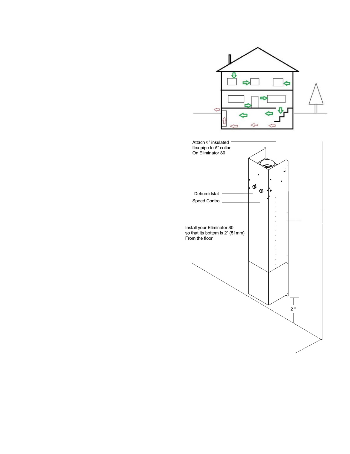
nuair ELIMINATOR 80 User manual

DOC RPM_EL80_010117006 1
THE ELIMINATOR 80
By
Installation, Operation and Care Manual

DOC RPM_EL80_010117006 2
CONTENTS:
This package contains the following items:
▪The Eliminator 80 (1—in two sections)
▪Height-adjustment screws (2)
▪6” Outside hood (1)
▪6” flexible insulated ducting (4 ft/1.22 m)
▪“Snap-lock” 6” galvanized pipe collar (to join flex pipe and outside hood)
▪Self-adhesive gasket (20 ft/6 m)
▪Tie wrap (“zip-tie”) (1).
REQUIRED TOOLS & MATERIALS:
To install the Eliminator 80 you will need the following tools and materials.
▪Reciprocating saw, jig saw or 6 ½” hole saw
▪Drill, measuring tape, screwdriver, utility knife, pliers (to cut flexible pipe ribbing as needed)
▪Outdoor caulking, caulking gun
▪Vapor barrier/duct tape
▪Appropriate (e.g. concrete, wood) screws and washers (typically 4-8) to mount Eliminator to the wall, screws
to mount pipe collar to hood (min. 3) and screws to fix hood to outside wall (4)
▪Sheet rock anchors (as needed for installation in finished areas).
*When considering use of a basement ventilator, be aware that your local building code might have
considerations surrounding their use (due to potential for negative air pressure) in mechanical rooms where a
standing pilot light is used in furnaces, hot water heaters, etc.

DOC RPM_EL80_010117006 3
Mounting
flange
HOW IT WORKS
A basement extractor is installed so that its intake section is
positioned just above the floor—right where heavy, damp air
collects. By pulling this heavy air out of the space, out go
unpleasant smells, damp air and factors which contribute to
mold growth. As this air is exhausted from the space, air
naturally moves in from the rest of the house and from
outdoors, by seeping into the home through tiny voids
around windows and doors, and into the basement space.
INSTALLATION INSTRUCTIONS:
1. Determine where the Eliminator 80 will be located.
It must be against an outside wall and should be near
an electrical outlet. Avoid conditions that may inhibit
air flow to the unit.
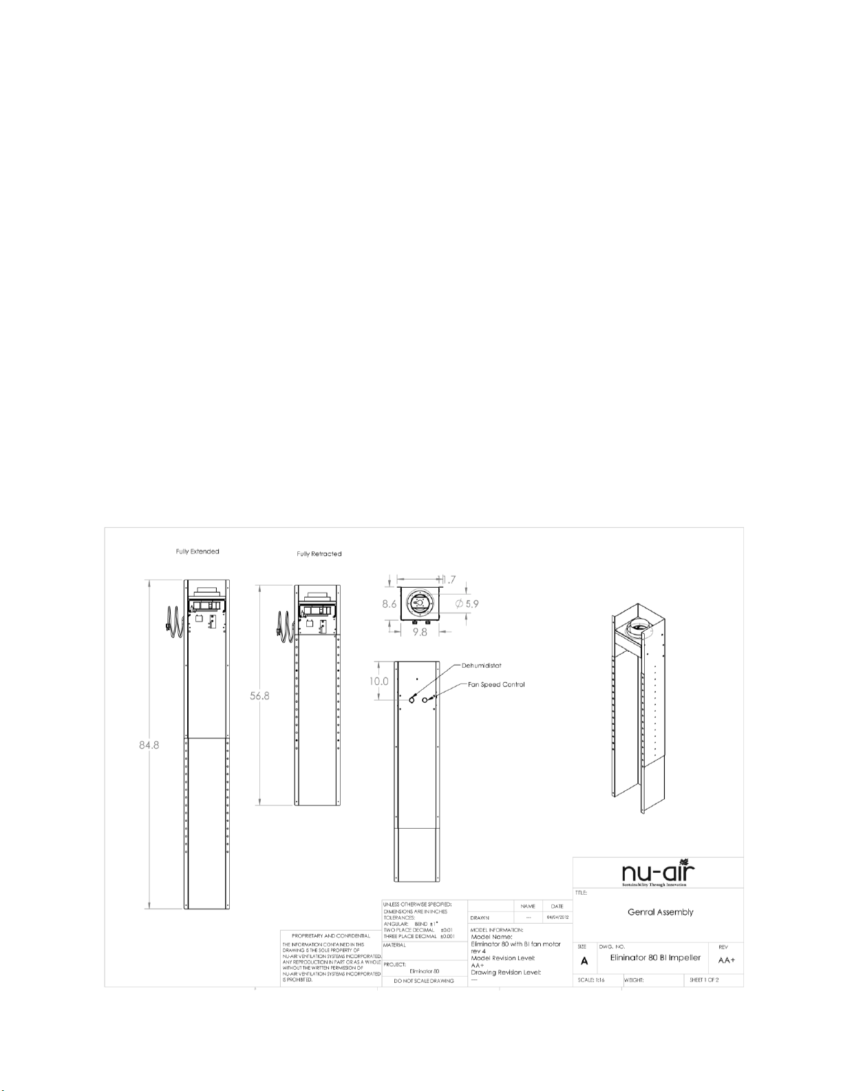
2. To set the height of the Eliminator 80, tighten the
adjusting screws on the side of the unit in the desired
position. The Eliminator 80 can be set on the
floor to draw air though its louvres. If you have a
model without louvers, or are using only the top
section, install so that the bottom edge of the
unit is raised 2 inches (51 mm) above the floor.
Cut two pieces of gasket material equal to the height
of the Eliminator 80. Attach to the back of the
mounting flanges to form an air seal against the wall.
3. Using a reciprocating, jig or hole saw, cut a 6½-inch
(152 mm) diameter hole through the wall or sill plate.
This is where you will run the flex pipe between the
Eliminator 80 and the outside hood. Before making
the hole, be sure there is no plumbing, electrical wire
or other obstruction behind the wall or outside.
4. Secure flex pipe and sheathing to the collar on the
Eliminator 80 with tie wrap(s) supplied.
5. Feed pipe to the outside for later hood connection.
6. Stand the Eliminator 80 against the wall where it is to
be mounted. Drill a pilot hole for your sheet rock
anchors (finished wall) using the predrilled holes in
the mounting flange of the Eliminator 80.
7. Insert the anchors and fasten the Eliminator 80 to the
wall using a washer and screw in each hole.
8. Outside of the house, connect the 6” pipe collar to the outside hood flange using 3 screws.
9. Cut the flex pipe to length so that it reaches over the collar, near the base of the outside hood.
10. Peel back the flex pipe insulation/sheathing. Tape the flex pipe, then insulation/sheathing, to the pipe collar
close to the base of the hood, allowing for a sturdy connection and a good seal.
11. Mount the hood to the outside wall using screws. Use caulking to seal between the house and hood.
12. Plug the Eliminator 80 power cord into a standard 120 V outlet.

DOC RPM_EL80_010117006 4
OPERATION:
As the need for ventilation will vary from home to home, the unit is
equipped with a humidity control and a speed control for flexible
operation. The humidity control monitors humidity. When the ambient
relative humidity (RH) exceeds the set point on the humidity dial, the fan
will go to high speed until RH drops below the setpoint. The speed
control is used to set fan speed for continuous operation (if desired)
whenever the humidity control is not triggering high speed operation.
Turing the speed dial clockwise from OFF changes fan speed from a
higher to a lower range. The table below explains various ways to operate
your Eliminator.
Operation
Set Humidity Dial to:
Set Speed control to:
OFF
OFF
OFF
Low Speed Continuous
OFF
Desired setting
High Speed Continuous
ON or OFF
High speed range
Intermittent High Speed, based on
ambient RH
Desired RH setting. Unit goes to
high speed while RH is above
setpoint.
OFF
Low speed with intermittent high
speed, based on RH
Desired RH setting.
Desired low speed setting.
Typical Humidity Dial Settings. Fall to spring: 40-60%; summer: OFF.
MAINTENANCE:
Every 3 months, check hood for blockage.
YOUR
NU-AIR
ELIMINATOR 80
TRANSFERABLE WARRANTY
(CANADA AND THE USA)
Should your NU-AIR Eliminator 80 cease to function within two (2) years of the original date of purchase due to
defective material or workmanship of the product, Nu-Air Ventilation Systems Inc. will replace FOB Factory the
defective part. Delivery, installation and labour cost are not covered by this warranty. This warranty does not
cover damage to the unit while your possession (other than damage by defective parts or material). Improper
maintenance voids this warranty. If the unit is put to commercial use or application other than residential use, the
warranty is for a period of one (1) year.
16 Nelson St., P.O. Box 2758, Windsor, Nova Scotia, B0N 2T0
www.nu-airventilation.com [email protected]
Tel: 902-798-2261 Fax: 902 798-2557
Table of contents
Popular Ventilation Hood manuals by other brands

Faber
Faber INLT21SSV Installation instructions; use and care information

FRAM
FRAM FDH-660HRBK manual

Baumatic
Baumatic Pythagora P25SS instruction manual

KitchenAid
KitchenAid LI31GA installation instructions

Whirlpool
Whirlpool GZ8330XLS1 parts list

Respekta
Respekta CH 1295 IXC N Operating & installation instructions