NuForce P-20 User manual

1
________________________________________________________________________________________________
382 South Abbott Avenue, Milpitas, CA 95035, USA • PHONE: +1-408-890-6840 • FAX: +1-408-262-6877
P-20
Preamplifier

2
________________________________________________________________________________________________
382 South Abbott Avenue, Milpitas, CA 95035, USA • PHONE: +1-408-890-6840 • FAX: +1-408-262-6877
FCC Notice - Declaration of Conformity Information
This equipment has been tested and found to comply with the limits for a Class B digital device,
pursuant to part 15 of the FCC Rules. These limits are designed to provide reasonable protection
against harmful interference in a residential installation. This equipment uses and can radiate radio
frequency energy and, if not installed and used in accordance with the instructions, may cause
harmful interference to radio communications.
However, there is no guarantee that interference will not occur in a particular installation. If this
equipment does cause harmful interference to radio or television reception, which can be determined
by turning the equipment off and on, the user is encouraged to try to correct the interference by one or
more of the following measures:
Reorient or relocate the receiving antenna.
Increase the separation between the equipment and receiver.
Connect the equipment into an outlet on a circuit different from that to which the receiver is
connected.
Consult the dealer or an experienced radio/TV technician for help.
WARNING: Only peripherals complying with the FCC class B limits may be attached to this
equipment.
Changes or modifications made to this equipment, not expressly approved by us or parties authorized
by us could void the user’s authority to operate the equipment. This device complies with part 15 of
the FCC Rules. Operation is subject to the following two conditions: (1) This device may not cause
harmful interference, and (2) this device must accept any interference received, including interference
that may cause undesired operation.
Notice for customers: The following information is only applicable to equipment sold in countries applying EU
Directives.
EU Declaration of Conformity
Hereby, NuForce Inc. declares that this device is in compliance with the essential requirements and
other relevant provisions of Directive 2004/108/EC.
The manufacturer of this product is NuForce, 382 South Abbott Ave, Milpitas, CA 95035, USA.
The Authorized Representative for EMC and product safety is NuForce, 382 South Abbott Ave, Milpitas, CA 95035,
USA.
For any service or guarantee matters please refer to the addresses given in separate service or guarantee documents.
For customers in Europe
Disposal of Old Electrical & Electronic Equipment (Applicable in the European Union and other
European countries with separate collection systems)
This symbol on the product or on its packaging indicates that this product shall not be treated as
household waste. Instead it shall be handed over to the applicable collection point for the recycling of
electrical and electronic equipment. By ensuring this product is disposed of correctly, you will help
prevent potential negative consequences for the environment and human health, which could
otherwise be caused by inappropriate waste handling of this product. The recycling of materials will help
to conserve natural resources. For more detailed information about recycling of this product, please
contact your local Civic Office, your household waste disposal service or the shop where you purchased
the product.

3
________________________________________________________________________________________________
382 South Abbott Avenue, Milpitas, CA 95035, USA • PHONE: +1-408-890-6840 • FAX: +1-408-262-6877
SAFETY INSTRUCTIONS
There are two categories of Safety Instructions included in this manual:
Product Warnings, (i.e., what must never be done to assure avoiding those hazards that could
cause bodily injury or property damage); and
User Directions (i.e., what must always be done to assure the safe use of your device).
The Safety Instructions contained in this manual have been categorized in accordance with the
seriousness of the potential hazards through the use of Signal Words. Those Signal Words, and their
intended meanings, are as follows:
DANGER: Indicates that a failure to observe the Safety Instructions could result in death or
catastrophic bodily injury.
WARNING: Indicates that a failure to observe the Safety Instructions could result in serious bodily
injury.
CAUTION: Indicates that a failure to observe the Safety Instructions could result in minor bodily
injury or property damage.
NOTE: Designates important information that relates to activities and/or conditions that might result
in loss of data and/or damage to your device.
Safe Use and Operation of Your Device
This equipment emits stray RF energy and will interfere with the reception of signals by airborne
electronic navigational devices or medical devices. Do not operate this equipment near any sensitive
medical devices.
WARNING: Use only grounded AC power cords.
Always immediately disconnect the power to the equipment in the event the device emits an unusual
odor or sound or generates smoke.
WARNING: Never attempt to disassemble, repair or make any modification to your device.
Disassembly, modification or any attempt at repair could cause bodily injury or property damage, as
well as damage to the device itself.
WARNING: Your device is not a toy. Never allow children to play with your device. Misuse, rough
or improper handling of your device by children could result in serious bodily injury for any of the
enumerated safety warnings in this manual. In addition, always keep all accessories and components
out of the reach of small children as small parts might present a choking hazard. Seek immediate
medical attention if choking occurs or if any small part has been swallowed.
CAUTION: Never raise the sound volume level too high when using your device with earphones. An
excessive sound volume level could cause damage to your hearing.
WARNING: To reduce the risk of fire or electric shock, do not expose the unit to moisture or water.
Do not allow foreign objects to get into the enclosure. If the unit is exposed to moisture, or a foreign
object gets into the enclosure, immediately disconnect the power cord from the wall. Take the unit to a
qualified service person for inspection and necessary repairs.
Read all the instructions before connecting or operating the component.
Keep this manual so you can refer to these safety instructions.
Heed all warnings and safety information in these instructions and on the product itself. Follow all
operating instructions.
Do not use this unit near water.
You must allow a minimum 10 cm or 4 inches of unobstructed clearance around the unit. Do not
place the unit on a bed, sofa, rug, or similar surface that could block the ventilation openings. If the
unit is placed in a bookcase or cabinet, there must be ventilation of the cabinet to allow proper cooling.

4
________________________________________________________________________________________________
382 South Abbott Avenue, Milpitas, CA 95035, USA • PHONE: +1-408-890-6840 • FAX: +1-408-262-6877
Keep the component away from radiators, heat registers, stoves, or any other appliance that produces
heat.
The unit must be connected to a power supply only of the type and voltage specified on the rear panel.
Connect the component to the power outlet only with the supplied power supply cable or an exact
equivalent. Do not modify the supplied cable.
Do not route the power cord where it will be crushed, pinched, bent, exposed to heat, or damaged in
any way. Pay particular attention to the power cord at the plug and where the cord exits the back of
the unit.
The power cord should be unplugged from the wall outlet during a lightning storm or if the unit is to
be left unused for a long period of time.
Immediately stop using the component and have it inspected and/or serviced by a qualified service
agency if:
The power supply cord or plug has been damaged.
Objects have fallen or liquid has been spilled into the unit.
The unit has been exposed to rain.
The unit shows signs of improper operation.
The unit has been dropped or damaged in any way.

5
________________________________________________________________________________________________
382 South Abbott Avenue, Milpitas, CA 95035, USA • PHONE: +1-408-890-6840 • FAX: +1-408-262-6877
P-20 Preamplifier
The wide-chassis P-20 offers a number of significant advances over its award-winning P-9
predecessor in several key areas, particularly with respect to volume control functions. A
preamplifier’s volume-control capabilities are among its most critical features. In practical terms, we
saw room for improvement over the already excellent P-9’s volume control, especially regarding noise
performance and transparency.
The P-20’s numerically controlled, switched-resistor ladder network features the latest in thin-film
technology. In order to improve precision and lower noise, we’ve implemented single thin-film, ultra-
low-noise resistors in the signal path for each of the volume control’s 0.5dB gain settings. This
permits the listener to achieve any desired volume level in meticulously precise 0.5dB steps. As a
further advantage, the listener is able to adjust any input’s level to precisely correspond with any other,
thereby simplifying the matching of source-component volume levels. The sculptural elegance of the
P-20’s rigid aluminum enclosure provides a stable, vibration-free foundation for all of the unit’s
exemplary features.
The heart of the P-20 boasts an all-discrete, precision-operational amplifier module. Speed is
paramount, so to reduce capacitive loading on the final voltage amp, the design incorporates ultra-
low-noise, monolithic dual JFETs, specially selected VMOS FETs, and extremely flat hFE bipolar
transistors in a dual cascode configuration, all combined with a "driven shield" arrangement. All this
is necessary to achieve an unprecedented 5MHz power bandwidth, a S/N ratio exceeding 100dB, and a
dynamic range in excess of 120 dB. The inherently stable P-20 gain circuit has no capacitors or DC-
servos in the signal path whatsoever.
Much attention has been paid to isolation. The amplifier modules are covered with thermal insulation
and then seated within heavy copper shields. This is necessary to prevent thermal drift or signal-
related heating effects capable of interfering with the preamp's finely tuned operation. Each amp
module also has a self-contained shunt regulator to increase its isolation from the power supplies. A
separate, isolated, floating-current source supply feeds each module to insure further isolation from
noise in the ground system. Then, all control functions are powered by a separate supply so that no
logic circuitry, with its clock signals and their correspondingly fast rise-times, ever introduce any
noise into the analog section's sensitive, low-level signals. While all of the above attention to detail
and overall isolation results in an extremely low noise floor, the included custom-designed remote
control also provides the user exemplary convenience.
In sum, the P-20’s near-to-molecular clarity offers the last word in utterly transparent, stress-free,
organic sound – in effect, a listening experience as close to live as high-end audio permits. Better still,
these features can be activated by a 12V trigger signal enabling integration without the need for
manual intervention. All that's needed is a processor or receiver with a common 12V trigger
connection.

6
________________________________________________________________________________________________
382 South Abbott Avenue, Milpitas, CA 95035, USA • PHONE: +1-408-890-6840 • FAX: +1-408-262-6877
User Guide
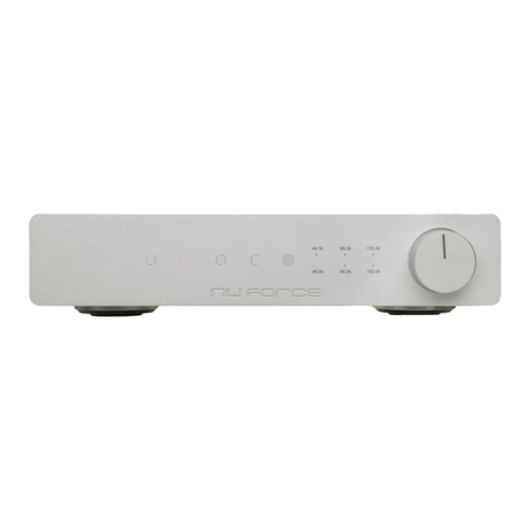
Although the P-20 Preamp represents state-of-the-art performance, operation couldn’t be simpler. To
start, you'll want to become familiar with the front panel’s touch-sensitive controls. From left to right,
they are as follow:
< = Previous Channel
= Power On/Off
> = Next Channel
Volume Display (in 0.5 dB steps)
- = Volume Down. Pressing for one second decreases volume by three steps.
x = Mute
+ = Volume Up. Pressing for one second increases volume by three steps.
The P-20 offers five selectable inputs to accommodate all of your source devices. Note that Input One
is divided into XLR and RCA connections. Pressing the Remote Control’s Input One key toggles
between XLR and RCA. When selecting from One to Five using the Remote Control, the selections
appear on the front panel in this sequence:
Input 1 XLR
Input 1 RCA
Input 2 RCA
Input 3 RCA
Input 4 RCA
Input 5 RCA
Note: Unlike many other XLR input connections, as a convenience, the P-20 offers the same voltage
gain for Input One XLR and Input One RCA.
To achieve a volume level that suits your requirements, volume selection occurs in increments of
0.5dB in 99 steps. As a further convenience, the onboard microprocessor memorizes each input’s last
selected volume setting, thereby achieving the desired volume for each of the five inputs without
having readjust the volume every time. This is a handy feature when evaluating source components.
Quick A/B comparisons at identical volume settings are by far the most reliable.
The included remote control is a straightforward device. But do bear in mind (to mention it again):
repeated operation of the Input One button causes the P-20 to toggle between Input One’s XLR and
RCA connections.
Dim Setup Mode:

7
________________________________________________________________________________________________
382 South Abbott Avenue, Milpitas, CA 95035, USA • PHONE: +1-408-890-6840 • FAX: +1-408-262-6877
With the P-20 in Power Off mode, the power supply and back panel switch must still be the ON
position. Pressing - and + together for three seconds permits entry into the Dim setup mode.
Use < and > to change the display’s brightness.
Press X to quit the Dim setup mode.
Time Setup Mode:
With P-20 in Power Off mode, the power supply and back panel switch must still be in the ON
position. Pressing < and > together for three seconds permits entry into the Time setup mode.
Use X to move to the next digit.
Use - and + to decrease or increase the time digit.
Press to quit Time setup mode.
Balance Adjustment:
There are times when you may want to make one channel louder than the other; for example, your
listening location is not precisely between the speakers. In other instances, a source component may
not provide perfectly balanced left-right output levels. Whatever the reasons, the ability to adjust left-
right balance can go a great way toward optimizing your listening experience. To store a left or right
balance offset, follow the instructions below. Once the process is complete, the P-20 will store the
setting in memory even if the unit’s power cable becomes unplugged. To restore the factory default
setting, i.e., no balance offset, simply depress the red button next to the AC power switch at the rear of
the unit for three seconds when the P-20 is powered On.
Balance Adjustment Procedure:
1) Power the P-20 On. Then push both the < and > buttons simultaneously. Hold < and > for
two seconds and then release. The P-20 will now be in the Balance Adjust Mode.
2) Next, use either the < or > button to select the input the balance of which you want to adjust.
3) If an increase of the right channel volume is preferred, push the + button. The display will
show R + X in steps from one through six. These increments reflect an increase of 0.5 dB
each, which provides a maximum offset of 6 x 0.5dB = +3dB of possible gain.
4) If you increase the right channel gain by too much, push the – button. It will decrease the
right channel volume by 0.5 dB for every increment down to 0, where channels will now be
the same.
5) If an increase of offset favoring the left channel is preferred, do the opposite of the above.
Start out by pushing the – button by up to six increments, which will increase the left channel
volume by up to +3dB. If you overshoot, push the + button to decrease left channel gain.
6) Just remember that you can only increase or decrease the gain of a given channel at any one
time. The controls do not allow you to increase one channel while decreasing the other. Only
a net increase of one channel with respect to the other is possible.
7) To exit at the setting you’ve chosen, push and hold the Mute X button for two seconds. The
display will return to the overall volume setting and operate normally from that point forward.
The programmed balance offset will be retained until you depress the red factory-default
button at the rear of the unit, as described above.
8) After adjusting a given input’s Balance, you can navigate to a different input by using the <
and > buttons and repeat the process for that input. If desired, each of the five inputs can
have its own independent Balance setting.
In closing, we're certain that you’ll find the P-20 to be the ideal cornerstone of any playback system,
however high-end. Irrespective of the source components, cables or amplifiers you’ve mated with it,
the P-20 will provide long years of flawless operation.

8
________________________________________________________________________________________________
382 South Abbott Avenue, Milpitas, CA 95035, USA • PHONE: +1-408-890-6840 • FAX: +1-408-262-6877
NuForce’s Limited Warranty and Limitation of Liabilities
ADDITIONAL RIGHTS
FOR CONSUMERS, WHO ARE COVERED BY CONSUMER PROTECTION LAWS OR REGULATIONS IN THEIR COUNTRY OF PURCHASE OR, IF DIFFERENT,
THEIR COUNTRY OF RESIDENCE, THE BENEFITS CONFERRED BY THIS WARRANTY ARE IN ADDITION TO ALL RIGHTS AND REMEDIES CONVEYED BY
SUCH CONSUMER PROTECTION LAWS AND REGULATIONS. THIS WARRANTY DOES NOT EXCLUDE, LIMIT OR SUSPEND ANY RIGHTS OF CONSUMERS
ARISING OUT OF NONCONFORMITY WITH A SALES CONTRACT. SOME COUNTRIES, STATES AND PROVINCES DO NOT ALLOW THE EXCLUSION OR
LIMITATION OF INCIDENTAL OR CONSEQUENTIAL DAMAGES OR ALLOW LIMITATIONS ON HOW LONG AN IMPLIED WARRANTY OR CONDITION
MAY LAST, SO THE LIMITATIONS OR EXCLUSIONS DESCRIBED BELOW MAY NOT APPLY TO YOU. THIS WARRANTY GIVES YOU SPECIFIC LEGAL
RIGHTS, AND YOU MAY ALSO HAVE OTHER RIGHTS THAT VARY BY COUNTRY, STATE OR PROVINCE. THIS LIMITED WARRANTY IS GOVERNED BY
AND CONSTRUED UNDER THE LAWS OF THE COUNTRY IN WHICH THE PRODUCT PURCHASE TOOK PLACE.
LIMITED WARRANTY
For a period of THREE(3) YEAR from the date of retail purchase by the original end-user purchaser (“Warranty Period”), NuForce warrants (i) this
product against defects in materials and workmanship, and (ii) that each Product, unmodified and under normal use and conditions, will
substantially comply with NuForce’ applicable written technical documentation for the Product. NuForce reserves the right to make substitutions
and modifications from time to time in the specifications of Products sold by NuForce, provided that such substitutions or modifications do not
materially affect overall Product performance.
If a hardware defect exists and a valid claim is received within the Warranty Period, at its option and to the extent permitted by law, Nuforce will
(1) repair the hardware defect at no charge, using new or refurbished replacement parts, (2) exchange the product with a product that is new or
which has been manufactured from new or serviceable used parts and is at least functionally equivalent to the original product, or (3) refund the
purchase price of the product. Nuforce may request that you replace defective parts with user-installable new or refurbished parts that Nuforce
provides in fulfillment of its warranty obligation. A replacement product/part assumes the remaining warranty of the original product or ninety
(90) days from the date of replacement or repair, whichever provides longer coverage for you. When a product or part is exchanged, any
replacement item becomes your property and the replaced item becomes Nuforce's property. When a refund is given, your product becomes
Nuforce's property.
OBTAINING WARRANTY SERVICE
If you purchased the product in the U.S., deliver the product, at your expense, to any Nuforce Service Center located in the U.S. If you purchased
the product outside of the U.S., deliver the product to any Nuforce Authorized Importer in the country where you purchased the product. Be
aware, however, that not all countries have Nuforce Authorized Service Providers (‘NASP’) and not all Authorized Service Providers outside the
country of purchase have all parts or replacement units for the product. If the product cannot be repaired or replaced in the country it is in, it may
need to be sent to a different country or returned to the country of purchase at your expense for repair or replacement. If you seek service in a
country that is not the country of original purchase, you will comply with all applicable import and export laws and regulations and be responsible
for all custom duties, V.A.T. and other associated taxes and charges. Where international service is available, Nuforce may repair or exchange
defective products and parts with comparable products and parts that comply with local standards.
You can always deliver the product to NuForce’s U.S. main service center for obtaining warranty service, however, you may have to pay for return
shipping cost.
Nuforce may send you user-installable new or refurbished replacement product or parts to enable you to service or exchange your own product
(“DIY Service”). Upon receipt of the replacement product or part, the original product or part becomes the property of Nuforce and you agree to
follow instructions, including, if required, arranging the return of original product or part to Nuforce in a timely manner.
When providing DIY Service requiring the return of the original product or part, Nuforce may require a credit card authorization as security for the
retail price of the replacement product or part and applicable shipping costs. If you follow instructions, Nuforce will cancel the credit card
authorization, so you will not be charged for the product or part and shipping costs. If you fail to return the replaced product or part as instructed
or the replaced product or part is not eligible for warranty service, Nuforce will charge the credit card for the authorized amount.
EXCLUSIONS AND LIMITATIONS
This Limited Warranty applies only to hardware products manufactured by or for Nuforce that can be identified by the "Nuforce" trademark, trade
name, or logo affixed to them. The Limited Warranty does not apply to any non-Nuforce hardware products or any accessories, even if packaged or
sold with Nuforce hardware. Non-Nuforce manufacturers, suppliers, may provide their own warranties. Other accessories distributed by Nuforce
under the Nuforce brand name are not covered under this Limited Warranty. This warranty does not apply: (a) to damage caused by accident,
abuse, misuse, misapplication, liquid contact, fire, earthquake, non-Nuforce products, or other external causes; (b) to damage caused by service
performed by anyone who is not a NASP; (c) to a product or a part that has been modified without the written permission of Nuforce; (d) to
consumable parts, such as batteries, or protective coatings designed to diminish over time unless failure has occurred due to a defect in materials
or workmanship; (e) to cosmetic damage, including but not limited to scratches, dents, and broken plastic on ports; (f) to defects caused by normal
wear and tear or otherwise due to the normal aging of the product; or (g) if any Nuforce serial number has been removed or defaced.
Important: Do not open the hardware product. Opening the hardware product may cause damage that is not covered by this warranty. Only
Nuforce or a NASP should perform service on this hardware product.
THIS WARRANTY AND REMEDIES SET FORTH ABOVE ARE EXCLUSIVE AND IN LIEU OF ALL OTHER WARRANTIES, REMEDIES AND CONDITIONS,
WHETHER ORAL OR WRITTEN, EXPRESS OR IMPLIED. NUFORCE SPECIFICALLY DISCLAIMS ANY AND ALL IMPLIED WARRANTIES, INCLUDING,
WITHOUT LIMITATION, WARRANTIES OF MERCHANTABILITY AND FITNESS FOR A PARTICULAR PURPOSE. IF NUFORCE CANNOT LAWFULLY
DISCLAIM IMPLIED WARRANTIES UNDER THIS LIMITED WARRANTY, ALL SUCH WARRANTIES, INCLUDING WARRANTIES OF MERCHANTABILITY AND
FITNESS FOR A PARTICULAR PURPOSE ARE LIMITED IN DURATION TO THE DURATION OF THIS WARRANTY. No Nuforce reseller, agent, or employee
is authorized to make any modification, extension, or addition to this warranty.
NUFORCE IS NOT RESPONSIBLE FOR DIRECT, SPECIAL, INCIDENTAL OR CONSEQUENTIAL DAMAGES RESULTING FROM ANY BREACH OF WARRANTY
OR CONDITION, OR UNDER ANY OTHER LEGAL THEORY, INCLUDING BUT NOT LIMITED TO LOST PROFITS, DOWNTIME, GOODWILL, DAMAGE TO OR
REPLACEMENT OF EQUIPMENT AND PROPERTY, ANY COSTS OF RECOVERING, REPROGRAMMING, OR REPRODUCING ANY PROGRAM OR DATA
STORED IN OR USED WITH NUFORCE PRODUCTS, AND ANY FAILURE TO MAINTAIN THE CONFIDENTIALITY OF DATA STORED ON THE PRODUCT.
NUFORCE SPECIFICALLY DOES NOT REPRESENT THAT IT WILL BE ABLE TO REPAIR ANY PRODUCT UNDER THIS WARRANTY OR MAKE A PRODUCT
EXCHANGE WITHOUT RISK TO OR LOSS OF PROGRAMS OR DATA.
9
________________________________________________________________________________________________
382 South Abbott Avenue, Milpitas, CA 95035, USA • PHONE: +1-408-890-6840 • FAX: +1-408-262-6877
Some states and provinces do not allow the exclusion or limitation of incidental or consequential damages or exclusions or limitations on the
duration of implied warranties or conditions, so the above limitations or exclusions may not apply to you. This warranty gives you specific legal
rights, and you may also have other rights that vary by state or province.
Proof of purchase in the form of a bill of sale or receipted invoice which is evidence that the unit is within the Warranty period must be presented
to obtain warranty service.
REPLACEMENT AS PROVIDED UNDER THIS WARRANTY IS THE EXCLUSIVE REMEDY OF THE CONSUMER.
NUFORCE SHALL NOT BE LIABLE FOR ANY INCIDENTAL OR CONSEQUENTIAL DAMAGES FOR BREACH OF ANY EXPRESS OR IMPLIED WARRANTY ON
THIS PRODUCT. EXCEPT TO THE EXTENT PROHIBITED BY APPLICABLE LAW, ANY IMPLIED WARRANTY OF MERCHANTABILITY OR FITNESS FOR A
PARTICULAR PURPOSE ON THIS PRODUCT IS LIMITED IN DURATION TO THE DURATION OF THIS WARRANTY.
Table of contents
Other NuForce Amplifier manuals

NuForce
NuForce MCA-18 User manual

NuForce
NuForce MCA-18 User manual

NuForce
NuForce DDA-100 User manual

NuForce
NuForce MCP-18 User manual

NuForce
NuForce Icon HD User manual

NuForce
NuForce P-9 User manual

NuForce
NuForce Icon Mobile User manual

NuForce
NuForce AVP-17 User manual

NuForce
NuForce DDA-120 User manual

NuForce
NuForce P-8S User manual

NuForce
NuForce STA120 User manual

NuForce
NuForce Ref 9 V2 Quick start guide

NuForce
NuForce AVP-18 Operating manual

NuForce
NuForce DAC-80 User manual

NuForce
NuForce Icon iDo User manual

NuForce
NuForce AVP-16 User manual

NuForce
NuForce udh-100 User manual

NuForce
NuForce HAP-100 User manual

NuForce
NuForce Dia User manual

NuForce
NuForce HA-200 User manual