Numato Lab Elbert User manual

Programming ELBERT
6. On-Board Peripherals
7. IO Connectors
8. Schematics and Files
Introduction
ELBERT is a simple but versatile FPGA Learning/Development board featuring Xilinx
Spartan 3A FPGA. ELBERT is an excellent choice for beginners and advance learners
for experimenting and learning system design with FPGAs. This development board
features Xilinx XC3S50A 100 pin FPGA with maximum 68 user IOs (Some are dedicated
for system). USB2 interface provides fast and easy configuration download to the on
board SPI flash. Yes that’s right! You don’t need a programmer or special downloader
cable to download the bit stream to the board. ELBERT features a stable clock source
which is derived from on board configuration controller. ELBERT incorporates LEDs
and switches for a curious user to get started with his “Hello World” program in a
matter of minutes.
Connection Details

This diagram should be used as a reference only. For detailed information, see
ELBERT schematics at the end of this documentation. Details of individual connectors
are as below.
1. USB
This USB mini connector is used for host interface and power. The board should be
connected to a powered USB Port.
2. IO Expansion (IO5)
Connected to FPGA user IOs. See schematics for individual connection details.
3. Module Expansion (IO1 – IO4)
The module headers can be used to attach optional peripheral modules. Find details
about peripheral modules elsewhere in this document.
4. Optional External 5V Input
For standalone operation, ELBERT cat be powered from an external 5V power supply.
This power supply input is optional if using USB. The solder jumper SJ7 on the back
side for the board needs to changed to "EXT POWER" inorder to use optional external
5V input.

Powering Up ELBERT
ELBERT is powered directly from USB port so make sure you are using a USB port that
can power the board properly. It is recommended to connect the board directly to the
PC instead a hub. It is practically very difficult to estimate the power consumption of
the board as it depends heavily on your design and the clock used. Xilinx ISE has tools
to estimate the power consumption. In any case if power from USB is not enough for
your application, external 5V can be applied to the board. Jumper PWRSEL should be
set up properly to use the board on external power. ELBERT requires three different
voltages. Two 3.3V supplies and a 1.3V supply. Onboard regulators derive these
voltages from the USB/Ext +5V. The board is shipped with test program already loaded
to FPGA and when powering up the board for the first time you can see the test pattern
on LEDs and can interact with the board using the switches.
Generating Configuration Bit Stream for ELBERT
HDL design needs to be converted to bit stream before it can be programmed to FPGA.
ELBERT at this time accepts only binary (.bin) bit stream created by XILINX ISE (
http://www.xilinx.com/tools/webpack.htm [1]). Once the HDL is synthesized, it is easy to
create a binary bit stream out of it. Please follow the steps below to generate binary bit
stream from your design using ISE WebPack.
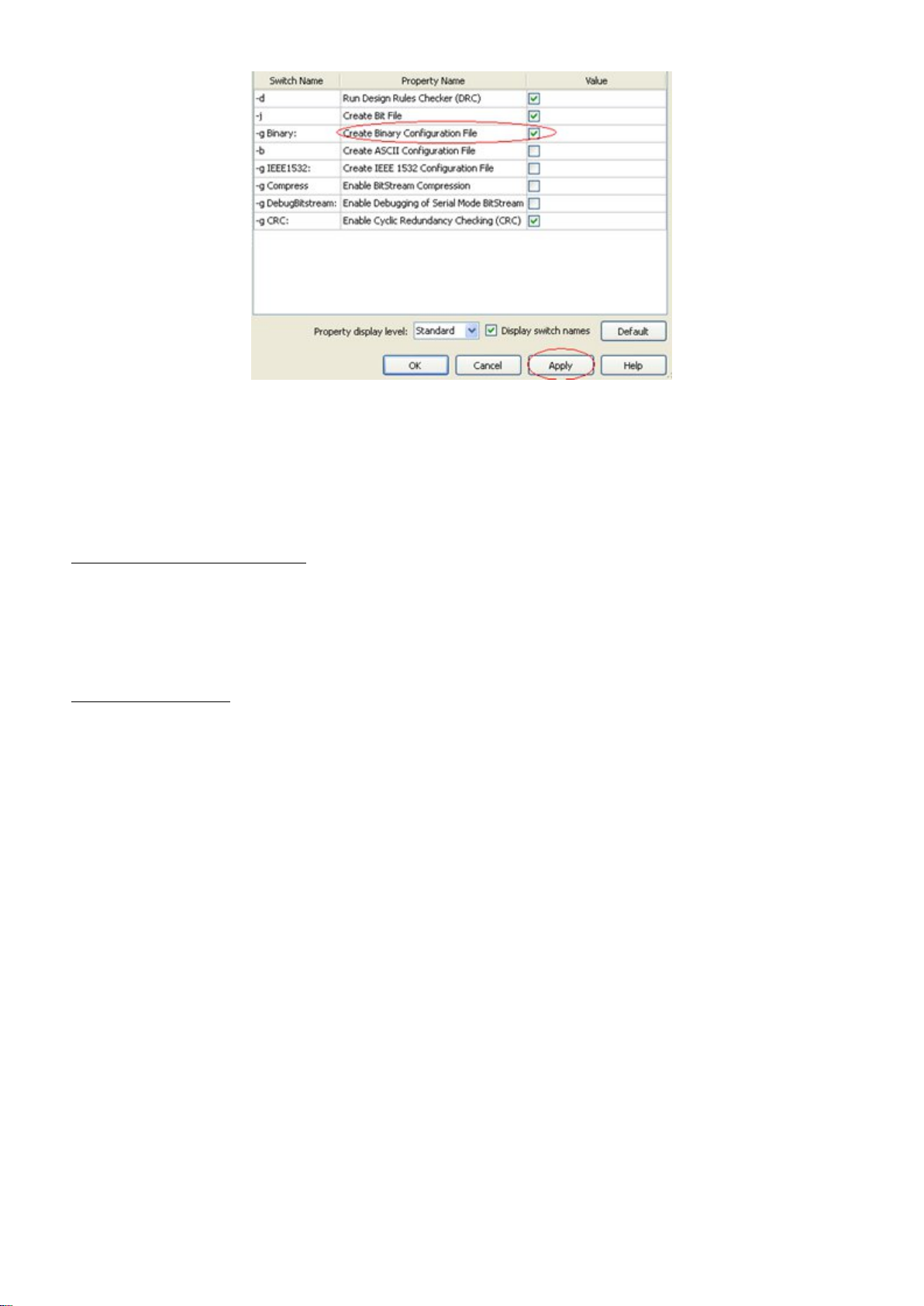
1. Right click on the “Generate Programming File” option in “Processes” window.
2. Select “Process Properties” from the popup menu. In the dialog box, check
“Create Binary Configuration File” Check box and click “Apply”.

3. Click “OK” to close the dialog box. Right click on “Generate Programming File”
option again and select “Run”. Now you will be able to see a .bin file in the project
directory and that file can be directly used for ELBERT configuration.
Programming ELBERT
ELBERT has an on-board microcontroller which facilitates easy reprogramming of on-
board SPI flash through USB interface. The microcontroller receives bit stream from
the host application and program it in to the SPI Flash and lets the FPGA boot from the
flash. The ELBERT configuration application can be downloaded from
www.numato.com [2] for free. When ELBERT is connected to PC, it shows up as a COM
port in Device Manager. Run configuration application, select proper COM Port before
downloading bit stream. Click on “Open File” to select the bit stream file (.bin) and
press “Program” button to download the bit stream. Wait till the download process is
finished. Once the download process is over, the configuration controller will try to
boot the FPGA from the SPI Flash automatically.

On-Board Peripherals
ELBERT is shipped with 1Mbit SPI flash memory on-board which is primarily used for
configuration storage. The first 500 kilobytes of SPI Flash memory will be used by
configuration storage and rest of the memory space can be used for user defined
purposes. Be careful not to write anything to first 500KB while using this memory for
data storage.
8 LEDs, four micro switches and one DIP8 switch are provided on-board for user
defined purposes. These peripherals are connected to FPGA IOs and can be controlled
from user RTL. The switches do not have pull-ups on board so make sure to enable
week pull ups on corresponding IOs in your design.
A 12MHz clock derived from the on board microcontroller oscillator circuit is available
on FPGA’s GCLK14 (Pin No. 40). This clock can be used to drive any user logic
implemented inside the FPGA. Other frequencies can be generated using DCMs
available on FPGA.
IO Connectors

The IOs that are not used for system purposes are available for user defined
applications on headers IO1, IO2, IO 3, IO4 and IO5. IO1, IO2, IO3 and IO4 have four IOs
along with 3.3V supply and ground. These headers can be used to connect optional
peripheral modules or user defined circuitry. For more information on IO connectors,
refer to ELBERT schematics.
Schematics and Files
Please download Schematics, Configuration Downloader tool and User constraints file
from the product page. [3]
Source URL: http://192.254.231.171/elbert-spartan-3a-fpga-development-board-user-guide
Links:
[1] http://www.xilinx.com/tools/webpack.htm
[2] http://www.numato.com/
[3] http://numato.com/elbert-spartan-3a-fpga-development-board
Table of contents
Popular Motherboard manuals by other brands

Texas Instruments
Texas Instruments AMC1100EVM user guide

Texas Instruments
Texas Instruments TPA3136D2 user guide

TYAN
TYAN Tempest i5000PX S5380 user manual

4gon
4gon RouterBOARD 411 Quick setup guide and warranty information

Texas Instruments
Texas Instruments TLV320AIC3212EVM-U user guide

AOpen
AOpen AX6BP user manual