NUVU SC Series User manual

SC Series
Slow Cookers
OWNER'S
MANUAL
Revised:
4 February 2010

NU-VU Food Service Systems® MENOMINEE, MICHIGAN 49858
(906) 863-4401 SALES FAX (906) 863-5889 • SERVICE FAX (906) 863-6322 (906) 863-4401
SC Series
TABLE OF CONTENTS
Nu-Vu® EQUIPMENT WARRANTY...................................................... 3
RECEIPT AND INSTALLATION............................................................ 5
INITIAL START-UP............................................................................... 7
OPERATING INSTRUCTIONS.............................................................. 9
MAINTENANCE AND CLEANING GUIDE............................................. 10
REPLACEMENT PARTS LIST .............................................................. 12
ELECTRICAL SCHEMATICS................................................................ 14

SC SERIES OWNER'S MANUAL Nu-Vu EQUIPMENT WARRANTY
NUVU EQUIPMENT WARRANTY
NUVUproductsarewarrantedagainstdefects inworkmanship andmaterials.Noother express warranty,writtenor
oral, applies. No person is authorized togive anyother warrantyorassume anyother liabilityon behalfofNUVU,
except bywritten statement from an officer ofNUVU.
Your NUVU equipment warrantyis limited to the following time periods for the original owner only:
PARTS LABOR
Inside the United States 24 Months 12 Months
All areas outside the United States 24 Months 12 Months
These time limits will applyin all cases unless prior arrangements havebeen made and agreed to inwriting.
The NUVU EQUIPMENT WARRANTY is composed of the following:
PARTS - -
This limitedwarrantycoverscertainelectrical, electronic, andmechanicalpartsforthetimeperiodsdescribedabove
with the exception ofthoseitems detailed under WarrantyLimitations. Customerswho maintain anopenaccount
maypurchaseagainst their account. MasterCard, Visa and American Express credit cards are also accepted.
The return of defective parts is required. The return of a defective part or component must be made prior to the
issuance of a credit on an open account. If a part that is returned tests satisfactoryin the NUVU factoryor at an
authorized NUVU dealer or service agency, NUVU may withhold issuing credit. Replacement parts will be
warranted for a period of ninety (90) days provided theyare installed in a manner authorized byNUVU.
LABOR - -
We require that you call our NUVU Service Department at (800) 338-9886 for service authorization BEFORE
you call any service agency if you wish to claim a labor expense under the warranty. We maybe ableto solve
your problem over the telephone, or we will schedule a warranty service call bya reliable service agencyin your
area.
WARRANTY LIMITATIONS:
NUVUwill payfor parts and labor under warrantyifthereis a defectivecomponent, but not for:
•Parts damaged in shipment beyond theconfines ofthe NUVU® factory.
• Normal operational wear and tear on the following parts -
Light bulbs and fuses
Door handles, catches and gaskets
• Damage attributable to customer abuse, including but not limited to-
Fan motor damaged from not following outlined Dry-Out Procedure
Lack of regular cleaning and/or maintenance
Leaks resulting from the removal of sealant in the unit
•Power supplyproblems, including -
Insufficient or incorrect voltage
Damage to electrical components caused bya power surge or spike
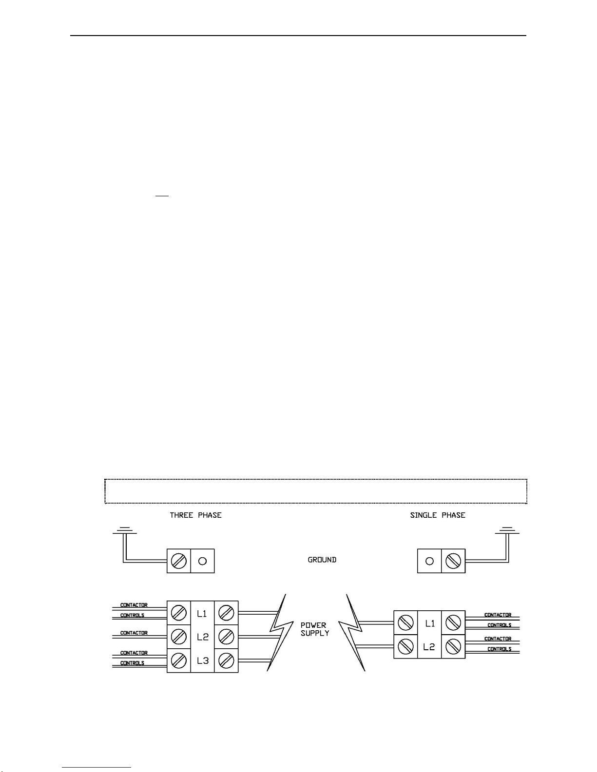
Incorrect installation (i.e., incorrect location ofhigh-voltage power leg for 240-volt 3-phase units)
Damage to electrical components resulting from use of an incorrect power supplycord or circuit breaker
•Operational problems resulting from customer's failure to follow established procedures outlined in the
Owner's Manual.
•Aservice call if nothing wrong is found (parts still work per spec when tested).
•Recalibration of temperature and humidity controls (all controls are carefully calibrated and tested at our
facility before shipment).
•Any equipment moved from the place of original installation unless NUVU agrees in writing to continue the
warrantyafter the relocation.
•Ongoing operational adjustments due to changing environmental conditions or normal wear and tear.
•Any overtime charges. NUVU will paystraight time onlyfor anywork performed on NUVU equipment.

Nu-Vu® EQUIPMENT WARRANTY SC SERIES OWNER'S MANUAL
Foodservice equipment and parts must be installed andmaintained inaccordancewith NUVUinstructions. Users
are responsible for the suitability of the units or parts to their application. There is no warrantyagainst damage
resulting from accident, abuse, alteration, misapplication, inadequate storage prior to installation, or improper
specification or other operating conditions beyond our control. Claims against carrier's damage in transit must be
filed by the buyer and, therefore, the buyer must inspect the product immediatelyupon receipt.
THIS WARRANTY DOES NOT COVER ADJUSTMENTS
DUE TO NORMAL ON-GOING USE!!!
PARTS RETURN PROCEDURES AND CONDITIONS:
The following procedure shall be followed for the return of parts to the factory for credit consideration:
•Allparts receivedbyNUVUmust haveacompletedReturnAuthorizationFormassupplied byNUVUwith
the part. Complete and return this Authorization Formwith the defective part(s).
•Parts MUST bepacked securelyso that in-transit damage cannot occur.
• Prepay shipment. Any parts returned collect will be refused byour Receiving Department. Credit will be
issued on proper returns only.
•As soon as parts are tested and confirmed as defective, credit will be issued against them.
•If the engineering test shows the component is not defective and in good working condition, it may be
returned to you along with your request for payment.

SC SERIES OWNER'S MANUAL Nu-Vu EQUIPMENT WARRANTY
RECEIPT AND INSTALLATION
RECEIPT:
It is essential to inspect the unit immediatelywhenit arrives. NUVUhas placed instructions onthe
packagingtohelpavoiddamageintransit.However,negligenthandlingcanproducehiddendamage.
These steps should be carefully followed:
A. Inspect the entire perimeter of the package for damage or punctures to the packing
material. This mayindicatedamagetotheunitinside. Callanyandallpackingdamagetotheattention
of the deliveryperson.
B. If anypacking damage is found uncrate the unit immediatelyin the presence of the delivery personto
determine if theunit is damaged. If anydamageis found indicatethetypeandamount ofdamageonthe
shipping documents and notifyNUVUat 1-800-338-9886 immediatelyafter filing a freight claim.
C.Uncratetheunit carefullyandchecktheentireunit(top, front,backand both sides)foranyvisibleorhidden
damage.
D. Remove the unit from the shipping pallet and inspect the bottom for any damage.
E. If any damage is noted after the driver leaves immediatelycontact the freight company and NUVU.
F.CheckeachOvenDoor.MakesuretheDoorclosescompletely,andthattheDoorGasketsealsfirmly.Ifthe
Gasket does not seal correctly please contact the NUVU Service Department for instructions and
assistance in any required adjustments.
INSTALLATION:
A.Checktodeterminethatthepowersourceisthesamevoltageandphaseasthatindicatedonthelabelonthe
side of the unit.
B. If you have received an SC7 you should attach the included Appliance Legs to the bottomof the unit.
Each Leg stud screws into a threaded hole in each corner ofthe base.
C. Position the unit where it is to be operated and adjust the Appliance Legs oftheSC-7 so theunit stands
levelandsolid.IfyouhaveanSC-14youmayneedtousemetalshims undertheCasterstoleveltheunit.
D. Make sure the GREASE PAN is installed inside the bottom of the unit. This PAN will catch most ofthe
drippings from your product as it is processed, making clean-up that much easier.
E. MakesuretheDRIP TROUGHisinstalledbeneaththeunit.ThisPANwillcatchtheliquidthatdrainsout
the front of the unit when the door is opened
F. Carefullyset all Controls and Switches to their OFF positions.
Electrical Connections

Nu-Vu® EQUIPMENT WARRANTY SC SERIES OWNER'S MANUAL
G.TheinstallingtechnicianorelectricianshouldcompletetheelectricalconnectionsbyremovingtheOutside
Top ofthe unit, this panel is heldinplace with two screws located on thetop oftheunit.Connect
the unit to the available power supply either through an attached cord and receptacleor through
direct wiring byfollowing these steps:
1.Take note of the labeling on the Power Terminal Block (Line 1, Line 2, Line 3, ).
2.Carefully identify the power source leads and attach them to the appropriate terminal connections.
Make sure all connections are clean and tight.
3.Properly ground the unit BEFORE USE byattachinga groundingwire to the Ground Lugor Clamp
provided next to the Power Terminal Block.
4.Allowenoughslackinthewiringtoallowforequipmenttobemovedaboutduringinstallationandany
future servicing.
H. Check thevoltage at the terminals on thePower Terminal Block with a voltmeter and comparethevalues
with the label listings on the side of the Oven. If the values match the unit is ready for its INITIAL
START–UP. If the readings DO NOT coincide you must call the NUVU Service Department for
instructions on changing the voltage and/or the phase.
I. Carefully position the Outside Top on the unit but do not press it into place. Position the unit in its final
operating location and refer to theappropriate INITIAL START–UP PROCEDURE for your unit.

SC SERIES OWNER'S MANUAL INITIAL START-UP
INITIAL START-UP
This START-UP procedure is used to verify that your NU-VU® SC Slo-Cooker has been
installed correctlyand willperformas intended when put into use. This INITIALSTART-UP
procedure should be carried out byyour electrician, licensed installer oraNU-VU®approved
service agency. Please read completely through all of this START-UP procedure before
beginning.
This procedure includes all optionalmanualfeatures for your SC model. If your unit doesnot
include one of these features you can skip over that step in the START-UP procedure.
Verify that the correct electrical supply has been properly installed.
Make sure all controls and switches are in their OFFpositions and engage the main
electrical supply.
Set the POWER switch to ON. The indicator light should illuminate.
Set the 24-HOUR TIMER to 2 hours time.
Set the HOLD control to 100F. The control indicator light should not light up.
Set the COOK control to 150F. The control indicator light should illuminate and
the HEATING ELEMENTS should begin to heat the Slo-Cooker.
Reset the 24-HOUR TIMER to 0. The COOK control should stop (its indicator
light will go out) and the HOLD control should activate (the indicator light will
illuminate).
Set the 24-HOUR TIMER to OFF. The HOLD control should stop (its indicator
light willgo out). The COOKcontrol should also be deactivated (the indicator light
will not illuminate).
Set the COOK control and the HOLD control to their OFF positions.
Set the COOK controlto 150F with the 24–HOUR TIMER in the OFFposition. The
red COOK indicator light should not illuminate. Set the PROBE control to 100F and
the PROBE switch to its ON position. The red PROBE and COOK indicator lights
shouldilluminate. AssoonastheOveninterior temperaturereachesthePROBE control
setting (100F) the PROBE indicator light should go out and the COOKcontrolshould
de-activate. Set the PROBE switch to its OFF position.
Set the 24–HOUR TIMER to 0, the HOLD control to 200F, and leave the COOK
controlset at 150F. The red HOLD indicator light should illuminate. Set the PROBE
switchto its ON position and the PROBE control to 125F. The red PROBE indicator
light should illuminate, the red COOK indicator light should illuminate, and the red
HOLD indicator light should go out. When the Oven interior temperature reaches the
PROBE control setting (125F) the red PROBE controlindicator light should go out,
the redCOOKcontrolindicator light should go out, and the red HOLDcontrolindicator
light should illuminate.
Return all switches and controls to their OFF positions.

INITIAL START-UP SC SERIES OWNER'S MANUAL
Clean the SC both inside and out according to all local and regional health
codes.
Repeat these listed steps to check out the operation of the lower Slo-Cook
section of the SC-14.
YOUR MANUAL CONTROL NU-VU® SC SHOULD NOW
BE READY FOR NORMAL OPERATIONS.

SC SERIES OWNER'S MANUAL OPERATING INSTRUCTIONS
OPERATING INSTRUCTIONS
The NU-VU®SC Series Slo-Cookers are designed to offer maximumflexibilityfor different
products. ManualControlunits are equipped with our COOK-N-HOLD feature, allowing you
to cook your product at one temperature and hold it at another. This lets you finishproducts
quickly, but stillholdthemat optimumtemperatures to prevent loss ofmoisture and resulting
shrinkage.
1) Set the POWER switch to its ON position. Select the correct cooking temperature
for your product on the COOK control and set the 24-HOUR TIMER to at least 1
hour, allowing the Slo-Cooker to preheat.
2) Prepare your product as outlined in your recipe. Load theprepared product into the
SC at your convenience.
3) Set the 24-HOUR TIMER to the required length of processing time your product
requires.
4) Set the HOLD control to the temperature you wish your finished product to remain
at. The 24-HOUR TIMER willautomaticallyshift control oftheOven'stemperature
from the COOK control to the HOLD control at the end of the timed processing
cycle. Your product will remain at the set HOLD temperature until the setting is
changed or the unit is turned OFF.
IMPORTANT: YOUR NU-VU® SC IS WELL INSULATED AND WILL MAINTAIN THE
ORIGINAL COOK TEMPERATURE FOR 1/2TO 1 HOUR DEPENDING ON THE
PRODUCT, PRODUCT DENSITY AND LOAD SIZE. THE TEMPERATURE WILL NOT
INSTANTLY DROP TO THE HOLD SETTING AT THE END OF THE TIMED COOK
CYCLE. PLAN YOUR COOK TEMPERATURE, COOK TIME AND HOLD
TEMPERATURE ACCORDINGLY TO MAINTAIN THE BEST POSSIBLE PRODUCT!!!

MAINTENANCE AND CLEANING GUIDE SC SERIES OWNER'S MANUAL
MAINTENANCE AND CLEANING GUIDE
NU-VU® equipment is designed to last for years of useful service. Careful consideration is
given in selecting components for durability, performance and ease of maintenance.
While NU-VU® equipment is designed for minimum care and maintenance certain steps are
required by the user for maximum life and effectiveness:
!Proper installation of the equipment.
!Correct application and usage of the equipment.
!Dry-out Procedures performed daily.
!Thorough cleaning on a regular basis.
EQUIPMENT INSTALLATION:
A. Install the NU-VU®SC Slow Cooker with adequate clearance around the unit.This
is important for cleaning and maintenance, as well as providing cooling air for the
Controls.
B. The installation must be on a level counter, table or floor to prevent the Door or
Doors from swinging when left in an open position.
C. The SC must be connected to the proper power supply as indicated on the
equipment label.
APPLICATION AND USAGE:
Each unit in the SC Series is designed for the low to medium temperatures normally
found in smoking and/or slow-cooking operations. IT IS NOT DESIGNED TO
OPERATE AT HIGH TEMPERATURES FOR LONG PERIODS OF TIME!!!
Continuous operation at maximum temperature settings may result in premature
component failure.
DRY-OUT PROCEDURE:
A. WIPE UP ANY STANDING LIQUIDS IN THE SLO-COOKER BOTTOM.
B. Set the POWER switch to the ON position. Set the COOKcontrolto 150Fand the
HOLD control to OFF. Set the 24-HOUR TIMER to 2 hours so that the COOK
control operates.
C. Leave the Doors open about 1" to 2". Allow the unit to run for approximately 30
minutes.
D. Set the POWER switch to the OFF position. Leave the Doors slightly open (about
1" to 2") while the unit is not in use.
THESE DRY-OUT PROCEDURES MUST BE CARRIED OUT DAILY TO
HELP MAINTAIN YOUR EQUIPMENT IN THE BEST POSSIBLE
CONDITION. THE REMOVAL OF ALL RESIDUAL MOISTURE IN THE
EQUIPMENT RETARDS ANY CORROSION OR DETERIORATION OF
THE INSULATION AND ELECTRICAL COMPONENTS AND EXTENDS
THE USEFUL LIFETIME OF YOUR NU-VU® EQUIPMENT.

SC SERIES OWNER'S MANUAL MAINTENANCE AND CLEANING GUIDE
CLEANING:
Your NU-VU®SC should be cleaned daily and as soon as possible after a spillhas occurred.
It is essential to maintain a clean unit, especially if the public views the unit in your place of
business. The following should be used for cleaning:
A. The stainless steel exterior may be cleaned with any good stainless steel cleaner or
polish, or with hot soapy water followed by a clear rinse if it is very soiled.
B. Any glass may be cleaned with any good glass-cleaning formula. Be sure to wipe
down the Door frame, and to clean the Gasket on the inside of the Door. Dried-on
debris or heavy soiling can be removed with hot soapy water followed by a rinse
with clean fresh water. Wipe the Door dryto prevent spotting.CAUTION:DONOT
USE ABRASIVE CLEANERS ON THE DOOR OR YOU MAY SCRATCH THE
GLASS!!!
C. Wipe up any standing liquids in the bottom of the Slo-Cooker and sweep up any
solid particles of debris.
D. The interior should be cleaned daily with mild soap and hot water followed by a
thorough rinse with clean fresh water and a sanitizing agent; wiping the interior dry
will help to prevent water spotting. Any water spotting and other mineral deposits
should be removed with any mild mineral removal agent as soon as they are
noticeable.
E. Leave the Door or Doors open by about 1" to 2" while the unit is not in use.
* * * CAUTION * * *
NU-VU® DOES NOT RECOMMEND the use of anystrong commercialor caustic product
on this equipment. DO NOT allow anytype of caustic cleaner to come into contact with any
aluminum parts (such as the Door Frame), the silicon rubber Door Gaskets, or any of the
sealant in the seams and joints. These caustic compounds may cause discoloration and/or
degradation of these parts, and may result in permanent damage. DO NOT use bleach or
bleach compounds on any chromed parts; bleach may damage chrome plating.
NOTE:
NU-VU® has had very good results with a product called JIFFY CLEANER. For standard
cleaning simplysprayJIFFY on and wipe off. Heavilysoiled areas mayrequire ashort period
of soaking. This cleaner is available through NU-VU® (Part #51-0002) or throughyourlocal
Rochester/Midland distributor or representative.

REPLACEMENT PARTS LIST
(SC SLO-COOKER Series)
Reference# Description Replacement Part #
ELECTRICAL COMPONENTS:
1 Power Terminal Block ................................................................................ 50-1332
2 Ground Lug/Clamp ..................................................................................... 50-1329
3 Contactor
120v coil .................................................................................................... 66-2013
240v coil..................................................................................................... 66-2017
4 Heating Element:
208v, 1000w...................................................................................... 60-0194
240v, 1000w...................................................................................... 60-0195
Thermal Overload prior to 07/01/11.......................................................... 252-1021
Thermal Overload after to 07/01/11............................................................. 66-1114
5 Temperature Control Sensors:
SC-7, SC-14 upper (4 ft).................................................................. 252-3001
SC-14 lower (10 ft)........................................................................ 50-0883-B
6 Cooling Fan Assembly
120v ........................................................................................................ 250-3001
240v ............................................................................................................. 97525
7 Electrical Relay, DPDT (120V)................................................................... 50-0433
8 Electrical Relay, DPDT (240V)................................................................... 66-9025
CONTROLS:
9Power Switch.............................................................................................. 66-3008
10 Cook Temperature Control:
425F Solid State............................................................................. 252-5008
Control Knob................................................................................ 253-2003
Indicator Light................................................................................... 50-0030
11 Hold Temperature Control:
250F Solid State............................................................................. 252-4001
Control Knob................................................................................ 253-2003
Indicator Light................................................................................... 50-0030
12 24-Hour Timer
120v ........................................................................................................ 252-1005
240v .......................................................................................................... 66-1160
Timer Knob............................................................................................... 253-2002

SC SERIES OWNER'S MANUAL REPLACEMENT PARTS LIST
INTERIOR COMPONENTS:
13 Side Rack (7-Tier).....................................................................................101-7013
14 Shelf ........................................................................................................101-0025
15 Grease Pan w/Handles and Plug...........................................................................47-9219
Grease Pan Plug only.................................................................................47-9279
EXTERIOR COMPONENTS:
16 Outside Top.............................................................................................47-2249-A
17 Appliance Legs:
6" Stainless Steel................................................................................50-0555
4" Chrome..........................................................................................50-0628
18 Caster..........................................................................................................50-0058
DOOR COMPONENTS:
19 Door:
Solid...................................................................................................47-9292
20 Door Hinge .................................................................................................50-1395
21 Latch Assembly CAM..................................................................................50-1407
Catch..................................................................................................50-1408
Handle Screws....................................................................................53-0016
Catch Screws .....................................................................................53-0403
22 Door Gasket
1 door........................................................................................................254-1011
2 doors .....................................................................................................254-1010


SC SERIES OWNER'S MANUAL ELECTRICAL SCHEMATICS

ELECTRICAL SCHEMATICS
Table of contents
Popular Slow Cooker manuals by other brands

Crock-Pot
Crock-Pot CPSCRM20-BP owner's guide

Crock-Pot
Crock-Pot CSC011X instruction manual

EUROPRO
EUROPRO KC272PW owner's manual

Silvercrest
Silvercrest 360599 2010 operating instructions

Continental Refrigerator
Continental Refrigerator Platinum CP43729 instruction manual

Continental Platinum
Continental Platinum CE33341 instruction manual