NVE Defender 500 User manual

Defender 500 | 1www.natvac.com | 800.253.5500
Defender 500
Owner’s Record
Date of Purchase: _________________________
Purchased from: __________________________
Serial Number: ____________________________
National Vacuum Equipment, Inc.

2| Defender 500 www.natvac.com | 800.253.5500
CONTENTS
Limited Warranty�����������������������������������������������������������������3
Warranty ����������������������������������������������������������������������������������������3
Defender 500������������������������������������������������������������������������7
General Suggestions���������������������������������������������������������������������7
Technical Data and Performances ������������������������������������������������7
PumpSpecications ����������������������������������������������������������������������8
Drive System ���������������������������������������������������������������������������������9
Factory Settings�����������������������������������������������������������������������������9
Operating Instructions �����������������������������������������������������11
Recommended Lubricant ������������������������������������������������������������ 11
Maintenance ��������������������������������������������������������������������������������12
Check Vane Wear������������������������������������������������������������������������12
Cold Weather Operation��������������������������������������������������������������12
Troubleshooting��������������������������������������������������������������� 13
Pump overheats ��������������������������������������������������������������������������13
Pump doesn’t turn �����������������������������������������������������������������������13
No vacuum�����������������������������������������������������������������������������������14
Vacuum/Pressure Changeover Valve �����������������������������������������15
Pump Layout ��������������������������������������������������������������������16
Vacuum Lines �����������������������������������������������������������������������������16
Technical Dimensions������������������������������������������������������������������17
Parts Diagram �������������������������������������������������������������������18
Parts List��������������������������������������������������������������������������������������19

Defender 500 | 3www.natvac.com | 800.253.5500
Warranty
National Vacuum Equipment, Inc�
Guarantees that the product it provides is free of manufacturer’s
defects, including materials and workmanship� Properly installed and
maintained product is warranted for a period of one (1) year subject to
the following conditions:
1� A properly completed warranty registration card must be received
by us within 30 days of sale to end user for pump sales to be
considered warrantable� All pumps received for warranty
consideration must retain the original NVE serial number tag�
2� The one (1) year period shall begin the day the product is shipped
from our warehouse, unless we are provided with an authentic
copy of the original resale invoice, in which case the one (1) year
period shall begin at such invoice date�
3� The covered product must be used in an application for which it
was intended� We do not recommend our product for particular
uses or applications�
4� Vane breakage, or damage caused by vane breakage, is not
warrantable�
5� Damage caused by improper use or lack of proper maintenance is
not warrantable�
6� Manufacturer’s liability under this or any other warranty, whether
express or implied, is limited to repair of or, at the manufacturer’s
option, replacement of parts which are shown to have been
defective when shipped�
NVE Defender 500
LIMITED WARRANTY

4| Defender 500 www.natvac.com | 800.253.5500
7� Manufacturer’s liability shall not be enforceable for any product
until National Vacuum Equipment, Inc� has been paid in full for
such product�
8� Except to the extent expressly stated herein, manufacturer’s
liability for incidental and consequential damage is hereby
excluded to the full extent permitted by law�
9� Manufacturer’s liability as stated herein cannot be altered except in
writingsignedbyanofcerofNationalVacuumEquipment,Inc.
10� Certain products provided by National Vacuum Equipment, Inc�
are covered by their respective manufacturer’s warranties (e�g�,
engines used in the NVE engine drive packages)� These products
are not covered by the National Vacuum Equipment, Inc�
Manufacturer’s Warranty�
11� Final assemblers responsibility� NVE goes to great lengths to
ensure the quality and proper functionality of the products it sup-
plies� Many products we supply are purchased for resale or are
impossible or impractical to test prior to the installation of the item
inavacuumsystem.Itisthereforetheresponsibilityofthenal
assembler to thoroughly test the vacuum system and components
suppliedtotheassemblerbyNVEpriortothedeliveryofthenal
product to the end user�
12� Not responsible for pump coupling tightness or alignment�
Customer needs to inspect periodically to ensure proper alignment
and to check tightness of set screws�
Any items found to be defective after delivery to the end user that
should have been discovered prior to deliver will qualify replacement
of the defective part only with absolutely no compensation for outside
labor or travel expenses� Any subsequent damage to other compo-
nents caused by the defective part will be the sole responsibility of the
assembler�

Defender 500 | 5www.natvac.com | 800.253.5500
WARRANTY PROCEDURES
Should a potential warranty situation arise, the following
Procedures must be followed:
• Contact your dealer or NVE immediately upon the occurrence of
the event and within the warranty period�
• Customer must receive a return goods authorization (RGA)
before returning product�
• All serial-numbered products must retain the NVE serial number
tagtobequaliedforwarranty.
• Product must be returned to NVE intact for inspection before
warranty will be honored�
• Product must be returned to NVE freight prepaid in the most
economical way�
• Credit will be issued for material found to be defective upon our
inspection, based upon prices at the time of purchase�

6| Defender 500 www.natvac.com | 800.253.5500
_______________________________
_______________________________
_______________________________
_______________________________
_______________________________
_______________________________
_______________________________
_______________________________
_______________________________
_______________________________
_______________________________
_______________________________
_______________________________
_______________________________
_______________________________
_______________________________
_______________________________
_______________________________
_______________________________
_______________________________
_______________________________
_______________________________
_______________________________
Notes

Defender 500 | 7www.natvac.com | 800.253.5500
The sliding vane vacuum pump, cooled by ballast air
induction, are supplied complete with:
• High temperature asbestos-free vanes
• Forced lubrication, oil pump with a remote oil tank
• 4-way vacuum/pressure changeover valve
• Non-return check valve
• Aluminum inlet/outlet connections
• “Ballast Port” cooling
General Suggestions ____________________________________________
• Designedforextendedoperation
• Ordinary and extraordinary maintenance has to be done
while the unit is stopped and the drive disconnected�
• Repairs on plumbing have to be done after disconnecting
pressure/vacuum from the same�
• Never start the pump if adequate safety devices are not
installed� Damaged safety equipment must be immediately
replaced�
• Be aware that the pump’s body can reach temperature of
over 280oFahrenheit�
• Maximumspeedshowninthetechnicalspecications
tablesmustnotbeexceeded.
NVE DEFENDER 500
Model-Specic
Information
Technical Data and Performances ____________________________

8| Defender 500 www.natvac.com | 800.253.5500
Pump Specifications _____________________________________________
PERFORMANCE AT 1200 R�P�M� - MAX SPEED
Normal Use _______________________________________________________
• The Defender 500 used for the suction of air for the movement of
liquids� Should be run at a max pressure of 21�8 PSI and a max
vacuum rate of 92%�
• As cooling is given by atmospheric air through the ballast system
pumps used to pressurize are for non-continuous duty�
• Overheating the pump will cause serious damage to the pump and/
or rotor seizure�
• Inordertomaximizeefciencyoftheballastaircoolingsystem,the
ltersmustbekeptclean.
Air Flow - CFM free air 310
Air Flow - CFM 60% vacuum 257
Max vacuum - % 92
Max absolute pressure-PSI 21�8
Weight-LBS 397
Oil consumption g/h=(drops / min) total 135 (80)
Remote Oil tank capacity - QT 5
Sound level at 60% vac� 7 m, dist - db(A) -
with silencer
84
108-500-D
CLOCKWISE SHOWN
SCALE 1 / 4
SECTION F-F
SCALE 1 / 2
SECTION G-G
SCALE 1 / 2
108-500-S
CCW SHOWN
SCALE 1 / 4
1
1
2
2
3
3
4
4
5
5
6
6
7
7
8
8
A A
B B
C C
D D
NVE National
Vacuum
Equipment, Inc.
2670 Aero Park Drive, Traverse City, MI 49686
Phone: (231) 941-0215 Fax: (231) 941-2354
TOLERANCES UNLESS OTHER WISE SPECIFIED
One place (.X) ±.1
Two places (.XX) ±.01
Three places (.XXX) ±.005
Angles ±1°
All machined surfaces 125 RMS max.
Remove all burrs and sharp edges.
CAD drawing - NO manual changes.
All dimensions in inches unless specified.
This document may contain confidential trade
secret information which is the exclusive
property of National Vacuum Equipment. Any
information on this drawing is not to be
disclosed to anyone not having a "Need to
Know." The information contained herein is to
be used only in accordance with the best
interests of National Vacuum Equipment.
PART NAME:
MATERIAL:
DRAWN BY:
SCALE:
CHECKED BY:
DATE:
BOB
PART NO.SHEET
2 108-500-D OR S
2 of
SEE BOM
APPROX. WT.
CAD FILE LOCATION: P:\Data\CAD - Production\108-500-D OR S.idw
SHEET SIZE D
DEFENDER 500, CW OR CCW
F
F
G
G(6.890)
(9.815)
(4.908)
(.752)
(11.170)
(11.417)
(5.275)
(31.617)
(8.751)
(3.000)
(3.150)
(16.879)
(8.195)
(21.726)
(1.499) (1.375)
(1.289)
(.375) SQ
(.3125) SQ
(1.201)
13.000
REVISION HISTORY
REV DATE DESCRIPTION APPROVED ZONE
A4/27/10 COMPLETE REDESIGN OF
ASSEMBLY ECN 1126 -
B6/9/2010
ITEM 22 802-063-500 WAS
120-063-500, CORRECT
OILPUMP
ECN 1132 C2
Filter
Valve
Figure 1

Defender 500 | 9www.natvac.com | 800.253.5500
• The pump must be installed so that it is easily accessible for
inspection and maintenance�
• The vacuum pump must be installed on a rigid base or stand� The
drive can be by shaft, belts and pulley, or hydraulic motor�
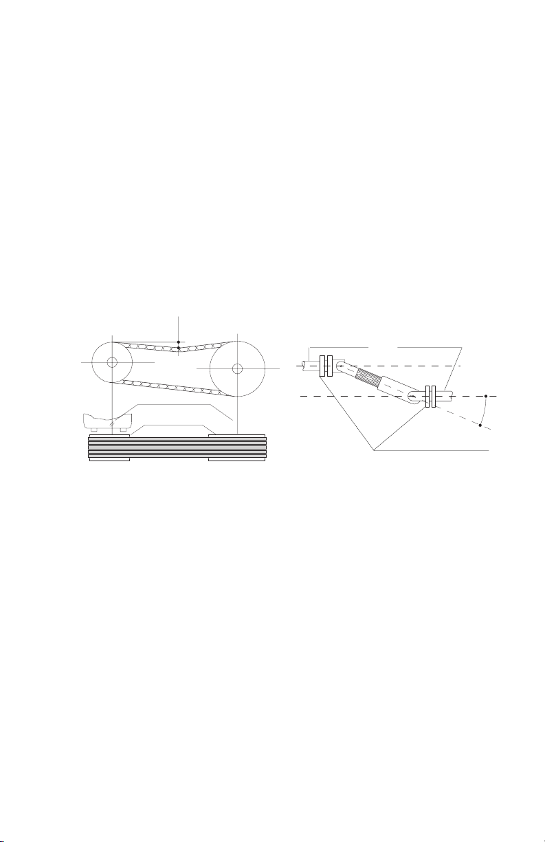
• The drive shaft must be mounted so that it does not create any
axial thrust; the inclination of the shaft must not exceed 15 degrees
(seeg.2)
• When using belts and pulley, the pulley can be mounted directly on
the rotor shaft on the larger diameter inboard portion of the shaft�
The alignment between the pulley of the pump and the driving
pulley must be thoroughly checked� The tension must be adjusted
sothebeltsexforabout1/16th between pulleys�
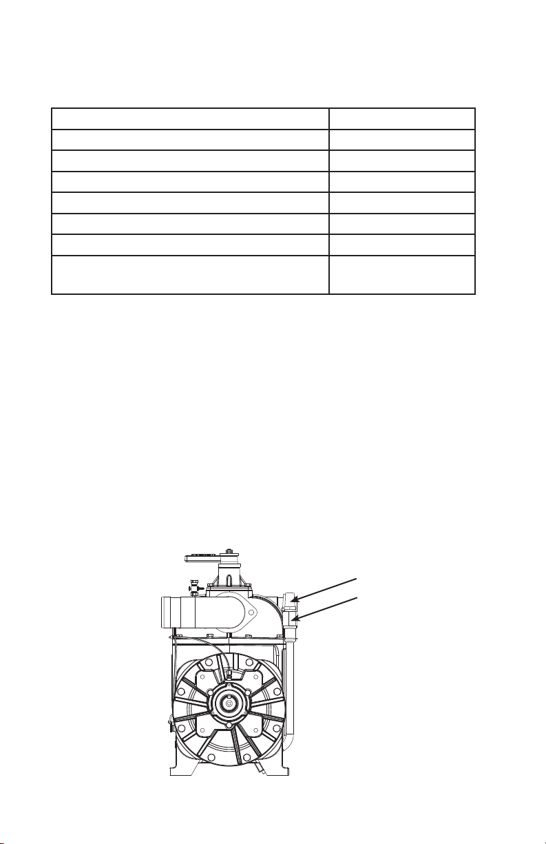
• The direction of rotation and RPM are marked on the front of the
pump�
• The direction of rotation required by your drive system should be
determined prior to ordering the pump�
Drive System ______________________________________________________
Direction of Rotation ___________________________________________
7
4. Installation
4.1 Checking at arrival
- upon receipt check that the pump and related accessories are
not damaged.
4.2 Pump mounting / Drive connection
- The pump must be installed so that it is easely accessible for
inspection and maintenance.
- The vacuum pump must be installed on a rigid base or stand.
The drive can be by cardan shaft, belts and pulley or by hydraulic
motor.
- The cardan shaft must be mounted so that it does not create any
axial thrust; the inclination of the shaft must not exceed 15°(see
fig. 2).
- When using the belts and pulley, the pulley can be mounted
directly on the rotor shaft eccept for R 430 .
For model R 430 pumps the pulley must be mounted with the
suitable support, supplied by JUROP.
The alignment between the pulley of the pump and the driving
pulley must be thoroughly checked.
The V-belts tension must be normal, that means the belts must
flex for about 2 cm. under the thumb pressure.
- With the hydraulic transmission the motor must be connected by
means of a support and a flexible joint.
The transmission must be protected according
to current safety standards (for Europe 89/
392 CEE standards).
Check that the actual shaft rotation
direction matches that of the arrow on
the label fixed on the front of the pump.
Fig. 2
15°
Transmission drive
Vacuum pump axle
axles must be parallel
16 - 20 mm
Flange must be
perfectly parallel
V-belts must be
exactly in line
- Check that the rotor/shaft is not blocked.
Figure 2

10 | Defender 500 www.natvac.com | 800.253.5500
Before starting-up the pump, check oil level in translucent tank�
Ifrellisneeded,usetherecommendedoilsshowninthenext
section�
Verifyoilisowingthrougheachlineatareasonablerate.
Oil lines are translucent to allow viewing oil�
Oil Usage Checking ______________________________________________
• The automatic lubrication pumps are set at the factory during pump
testing and should require no further adjustment during pump
installation� The pump should consume 12oz - 15oz of oil per hour�
Please contact us if oil usage is outside of these parameters�
• It is the responsibility of the installer to ensure proper vacuum relief
settings, pressure relief settings and RPM�
Factory Settings _________________________________________________

Defender 500 | 11www.natvac.com | 800.253.5500
Recommended Lubricant ______________________________________
• We recommend that non-synthetic turbine oil be used in our
pumps� Turbine oil is much more resistant to breakdown due to
heat than normal motor oil, thereby avoiding the problems
associated with motor oil such as lacquering and excessive wear�
Acceptable oils include:
1� *NVE ISO 68 Oil
2� Penzoil Penzabell 68 T�O�
3� Shell Turbo 68
4� Mobil D�T�E� Heavy - Medium
5� Texaco Regal R & O 68
* NVE ISO 68 Oil is our recommended pump oil for the Challenger
series vacuum pumps� Challenger Vacuum Pump Oil is sold by the
case, six-1 gallon containers of oil per case�
OPERATING INSTRUCTIONS

12 | Defender 500 www.natvac.com | 800.253.5500
Ordinary maintenance
•Re-llthelubricationoiltankperiodically
•Checkthatthedriveprotectionsareproperlyxed
•Cleantheltersoftheinjectionvalves(ballastports)
Checking Vane Wear
• We recommend checking vane wear at least every 12 months�
• Anewvaneisushwiththeoutsidediameteroftherotor.
• Unscrewtheplug(g.3)andinsertarodofdia.1/4”andturnthe
shaft by hand� With the checking rod touching the outside diam-
eteroftherotor,markitarsttimewithascribe.Continueturning
the shaft until the checking rod falls inside a vane groove touching
the vane� Mark the rod a second time� If the distance between
the two marks exceeds 3/16” the vanes must be replaced� Once
nishedthecheckingprocedurereplacetheplugof(g.3).
• Vanes should be replaced in sets and it is always a good idea to
have an extra set of vanes on hand for emergencies�
Figure 3
Maintenance _____________________________________________________
108-500-D
CLOCKWISE SHOWN
SCALE 1 / 4
SECTION F-F
SCALE 1 / 2
SECTION G-G
SCALE 1 / 2
108-500-S
CCW SHOWN
SCALE 1 / 4
1
1
2
2
3
3
4
4
5
5
6
6
7
7
8
8
A A
B B
C C
D D
NVE National
Vacuum
Equipment, Inc.
2670 Aero Park Drive, Traverse City, MI 49686
Phone: (231) 941-0215 Fax: (231) 941-2354
TOLERANCES UNLESS OTHER WISE SPECIFIED
One place (.X) ±.1
Two places (.XX) ±.01
Three places (.XXX) ±.005
Angles ±1°
All machined surfaces 125 RMS max.
Remove all burrs and sharp edges.
CAD drawing - NO manual changes.
All dimensions in inches unless specified.
This document may contain confidential trade
secret information which is the exclusive
property of National Vacuum Equipment. Any
information on this drawing is not to be
disclosed to anyone not having a "Need to
Know." The information contained herein is to
be used only in accordance with the best
interests of National Vacuum Equipment.
PART NAME:
MATERIAL:
DRAWN BY:
SCALE:
CHECKED BY:
DATE:
BOB
PART NO.SHEET
2 108-500-D OR S
2 of
SEE BOM
APPROX. WT.
CAD FILE LOCATION: P:\Data\CAD - Production\108-500-D OR S.idw
SHEET SIZE D
DEFENDER 500, CW OR CCW
F
F
G
G(6.890)
(9.815)
(4.908)
(.752)
(11.170)
(11.417)
(5.275)
(31.617)
(8.751)
(3.000)
(3.150)
(16.879)
(8.195)
(21.726)
(1.499) (1.375)
(1.289)
(.375) SQ
(.3125) SQ
(1.201)
13.000
REVISION HISTORY
REV DATE DESCRIPTION APPROVED ZONE
A4/27/10 COMPLETE REDESIGN OF
ASSEMBLY ECN 1126 -
B6/9/2010
ITEM 22 802-063-500 WAS
120-063-500, CORRECT
OILPUMP
ECN 1132 C2
Vanes wear
control plug

Defender 500 | 13www.natvac.com | 800.253.5500
Conrmpumpisnotfrozen.
• Priortoengagingthepump,turnbyhandtoconrmitisnotfrozen.
Ifpumpisfrozen,thawit.
• If the pump is frozen, thaw it out by heating the bottom of the pump
with a torch or move the truck into a heated building�
Avoidfreezingproblems
• You can avoid freezing problems by putting a small amount of
diesel fuel into the pump at the end of the day�
Cold Weather Operation ________________________________________

14 | Defender 500 www.natvac.com | 800.253.5500
Defender 500
Vacuum Pump
Cause Correction
Faulty lubrication Check the lubrication
Oilmissing Re-llthetank
RPM to high Reduce RPM
Operation-time too long at Stop the pump for a while and
high vacuum let it cool down�
Cloggedltersof“ballastport” Thoroughlycleanthelters
injection valves�
Cause Correction
Drip-oiler/s badly adjusted Adjustment as described
Oiler’s pin not sealing Clean the related seat�
Cause Correction
Broken vanes due to suction of Dismount the pump and replace
damaged parts, foreign objects, damaged parts� Check primary
or bad lubrication� shut-off and lubrication system�
Frozen pump Unfreeze the vacuum pump
Damaged drive system Check and replace damaged
parts�
Flange bolts too tight Loosen the bolts
TROUBLESHOOTING
Pump overheats ________________________________________________
Pump uses too much oil ________________________________________
Pump doesn’t turn _______________________________________________

Defender 500 | 15www.natvac.com | 800.253.5500
Cause Correction
Change-over lever in neutral position Place lever in correct position
as shown�
Worn sliding-vanes Replace the vanes
Loose check-valve Replace the valve
Worn lip seals Replace the seals
Blocked vacuum pump See previous instructions
Leaking of the gate-valves on the tank Tighten the valves
Leaking of the seals on the tank Repair or replace the seals
Primary shut-off blocked Dismount and clean the parts
Clogged connecting pipeline Clean the metal pipelines or
replace the rubber ones�
No vacuum _______________________________________________________

16 | Defender 500 www.natvac.com | 800.253.5500
Layout of vacuum line
1� Primary shutoff
2� Tank
3� Secondary Shutoff
4. SilencerandOilCatchMufer
5� Vacuum Pump
6� Safety Relief Valve
• The mounting of a secondary shutoff (pos� 3) is suggested in
between the pump and the tank, for protecting the vacuum pump�
• A silencer (pos� 4) is suggested in order to reduce sound level�
6
5
3
6
12
66
4
PUMP LAYOUT

Defender 500 | 17www.natvac.com | 800.253.5500
F
F
G
G(6.890)
(11.170)
(11.417)
(5.275)
(31.617)
(8.751)
(3.000)
(3.150)
(16.879)
(8.195)
(21.726)
SECTION F-F
SECTION G-G
(1.499)
(1.375)
(1.289)
(.375) SQ
(.3125) SQ
(1.201)
(9.815)
(4.908)
(.752)
13.000

18 | Defender 500 www.natvac.com | 800.253.5500
108-500-D
CW SHOWN
SCALE 1 / 4
DETAIL E
SCALE 1 / 2
1
1
2
2
3
3
4
4
5
5
6
6
7
7
8
8
A A
B B
C C
D D
NVE National
Vacuum
Equipment, Inc.
2670 Aero Park Drive, Traverse City, MI 49686
Phone: (231) 941-0215 Fax: (231) 941-2354
TOLERANCES UNLESS OTHER WISE SPECIFIED
One place (.X) ±.1
Two places (.XX) ±.01
Three places (.XXX) ±.005
Angles ±1°
All machined surfaces 125 RMS max.
Remove all burrs and sharp edges.
CAD drawing - NO manual changes.
All dimensions in inches unless specified.
This document may contain confidential trade
secret information which is the exclusive
property of National Vacuum Equipment. Any
information on this drawing is not to be
disclosed to anyone not having a "Need to
Know." The information contained herein is to
be used only in accordance with the best
interests of National Vacuum Equipment.
PART NAME:
MATERIAL:
DRAWN BY:
SCALE:
CHECKED BY:
DATE:
BOB
PART NO.SHEET
2 108-500-D OR S
1 of
1/4
SEE BOM
APPROX. WT.
CAD FILE LOCATION: P:\Data\CAD - Production\108-500-D OR S.idw
SHEET SIZE D
397 LBS
DEFENDER 500, CW OR CCW
PARTS LIST
ADD'L INFO
DESCRIPTIONPART NUMBERUOMQTYITEM
D500, HOUSING, MACHINED120-001-260EA11
NOTE 7VANE, DEFENDER 500120-007-260
EA5
2
O-RING, 2-267 VITON120-064-010EA23
D500 GEN2, ENDPLATE, MACHINED120-003-500
EA
2
4
GASKET, END CAP, 260120-056-2601EA25
D500 BEARING COVER, MACHINED120-054-004
EA16
SEAL, 40 X 72 X 15 DC, VITON120-018-500-3
EA17
WAVE WASHER, D500120-046-001EA28
BEARING, BALL-6308120-019-406
EA
29
SEAL, 48 X 72 X 15 DC, VITON120-018-260-2EA210
NOTE 2, 4FITTING, STRT 1/8 NPT-TUBE320-408-004
EA
9
11
SEAL SLEEVE, D500120-009-260
EA
212
NOTE 4
ADAPTER, LONG ELBOW 1/8 MBSPT-FNPT
320-408-003EA213
ROTOR, D500 STUFFED120-005-500
EA114
SEE NOTE 12
KEY, 5/16 x 5/16 x 2" 1018 BER
120-006-500EA115
SEE NOTE 12KEY, 3/8" X3/8" X 2120-006
EA116
NOTE 8
OIL LINE, 1/8" OD PFA
320-407-001
FT
6.86517
NOTE 8
OIL LINE PROTECTOR, 1/4"
320-409-002FT6.19818
NOTE 4PLUG, 1/4" BSPT120-059-001
EA1
19
GASKET, MANIFOLD, 260120-039-260EA120
D500, CHECK VALVE, EXHAUST120-041-260
EA1
21
ELBOW, ALUM D500802-063-500
EA
2
22
FLANGE, D500 4-WAY120-063-001EA223
O-RING, 2-336 VITON120-064-009
EA
224
D500 MANIFOLD, MACHINED120-309-260EA125
P-CLIP, OIL LINE 1/4" X 5/16320-409-003
EA
326
GASKET, TOWER 260120-040-260
EA
127
NOTE 4
Valve, Drain 1/8" NPT
120-102EA128
D500, PLUG, MACHINED120-062-260
EA1
29
SPRING, 4-WAY VALVE, 260120-045-260EA130
D500, TOWER, MACHINED120-065-260
EA1
31
SEAL, 27 X 41 X 10 ADL, NITRILE (27 X 41 X 7 ADL OPTIONAL)
120-018-260
EA
132
D500, HANDLE, 4-WAY120-060-260EA133
WASHER, BRASS, VALVE HANDLE, D500120-099-260-B
EA1
34
NOTE 4
Filter, 3/4"NPT
120-099-406-SEA235
BRACKET, OIL LINE D500320-083-007
EA1
36
NOTE 4
ADAPTER, ELBOW 1/8 BSPTM-NTPF
320-408-001EA537
Drive Tab
320-LF8EA138
D500, OIL PUMP MOUNT, MACHINED120-054-500
EA1
39
NOTE 6
Gasket, Oil Pump
320-R31EA140
FITTING, ELBOW 1/4" OD X 1/8" NPTF WORLD320-006
EA141
GUARD, OIL PUMP 607 POWDERCOAT120-079-001EA142
NOTE 5, 6OIL PUMP, 4 PORT CW
OIL PUMP, 4 PORT CCW
320-LW32-BD
320-LW32-BS
EA143
BALLAST PORT CHECK VALVE VENT120-099-406-4EA244
WASHER, .920"ODx.406"IDx.135"120-099-406-3
EA
2
45
SPRING, 406 BALLAST PORT CHECK120-099-406-6EA246
Body, Ballast port check
120-099-406-5EA247
BRACKET, BALLAST TUBE, 260120-088-260
EA
248
SEALING WASHER, ALUM 3/8" BSPP
120-099-260-1EA249
PLUG, 3/8" BSPP120-047-002
EA
250
BALLAST TUBE WELDMENT, D500120-096-001EA251
NOTE 3
FITTING, COMPRESSION 18MM X 1/2" NPT120-186-260C
EA252
E
FASTENERS: NON-INVENTORY (SEE NOTE 1)
DESCRIPTION
PART NUMBER
QTY
ITEM
Toothed Lock Washer
DIN 6797 - J 10.516301
Metric Hex Cap Screw
ANSI B18.2.3.1M - M10 x 1.5 x 2516302
Metric Hex Cap ScrewANSI B18.2.3.1M - M8 x 1.25 x 2018303
Spring Washer
DIN 127 - A 818304
Washer, Fender 3/8" x 1 3/4" X 3/16" THICK, PLATEDFW - 3_8 X 1.75
1
305
Hex Jam NutANSI B18.2.4.5M - M8 x 1.252306
ISO metric hexagon socket set screwsAS 1421 - M8 x 40 Flat Point
1
307
SHCS - 1_4-20 UNC X 0.75SHCS - 1_4-20 UNC X 0.752308
HHCS - 1/2-13 UNC X 1.00
HHCS - 1_2-13 UNC X 1.00465
LOCK WASHER, 1/2LW - 1_2
4
66
ACCESSORIES LIST (PACKAGE SEPARATELY) SEE NOTE 11
DESCRIPTION
PART NUMBER
UOMQTY
ITEM
PIN, T-HANDLE, .250 X 4"
120-0T5EA2201
FITTING, 1/4" TUBE X 1/8" NPTF WORLD320-005
EA1
202
OIL LINE, 1/4"OD X 3/16"ID PFA
320-407-002FT5203
FILTER, OIL TANK PLASTIC320-083-001
EA1
204
OIL TANK, 5QT, W/LOGO
320-082-001
EA
1205
CAP, OIL TANK, BLACK 2 1/4"
320-083-002EA1206
OWNERS MANUAL - DEFENDER 500OWNERS MANUAL - D500
EA1
207
50
49
51
52
1
2
14 11
13
3
4
302
301
11
10 9
8
5
7
6
304
303
12
22
23
24
20
25
26
27
28
30
22
29
31
32
33
34
306
307
305
303
304
48
302
301
26
36
11
37
12
9
38
8
5
39
304
303
40
37 11
43
42
41
37
11
10
NOTES:
1. ALL FASTENERS ARE GRADE 8 UNLESS OTHERWISE SPECIFIED.
2. BRASS COMPRESSION FITTING ASSEMBLY INSTRUCTIONS: FIRST TIME-FINGER
TIGHT PLUS ONE WRENCH TURN. REMAKE INSTRUCTIONS: FINGER TIGHT PLUS
1/16 TURN. APPROX. 8 REMAKES ARE POSSIBLE WITH THIS SETUP.
3. TIGHTEN COMPRESSION NUT OF 18 MM FITTING FINGER TIGHT PLUS 1/4
TURN. TIGHTEN NPT THREADS FINGER TIGHT PLUS 1 FULL TURN. USE TEFLON
TAPE AS NEEDED.
4. WRAP ALL PIPE THREAD FITTINGS AND OTHER THREADS REQUIRING SEALING
WITH TEFLON TAPE, 3 WRAPS MINIMUM.
5. PRESET OIL PUMP FLOW BY BACKING OFF ADJUSTING SCREWS FULLY CCW
(FULL FLOW) AND TURNING EACH SCREW 5 1/2 TURNS CW TO REDUCE FLOW
(APPROXIMATELY 1 DROP/7 SECONDS/PORT). SEAT LOCKING NUTS. VERIFY
REASONABLE FLOW THROUGH OIL LINES DURING ONE HOUR TEST.
6. APPLY SEALANT TO BOTH SIDES OF OIL PUMP GASKET BEFORE ASSEMBLY. USE
EITHER LOCTITE AVIATION GASKET SEALANT #30517, PERMATEX AVIATION FORM
A GASKET #80019 OR EQUIVALANT.
7. BRUSH A LIBERAL AMOUNT OF ISO 68 TURBINE OIL TO THE VANES BEFORE
INSERTING INTO ROTOR SLOTS.
8. PRE-CUT OIL LINE AND PROTECTOR TO THE BELOW LENGTHS:
320-407-001 320-409-002 108-500-D (CW) 108-500-S (CCW)
10.25" 8.25" REAR BORE REAR BORE
7.875" 5.875" REAR BEARING REAR BEARING
32.50" 30.50" FRONT BORE FRONT BEARING
31.75" 29.75" FRONT BEARING FRONT BORE
9. PAINT PUMP GREY AFTER ALLOWING TO COOL AND AFTER CLEANING OFF ALL
OILS/DIRT. USE PPG ACR-100 ACRYLIC LACQUER OR EQUIVALENT AND PROCESS
PER MANUFACTURERS REQUIREMENTS WITH THE EXCEPTION OF PRIMING METAL.
EXCEPTION TO PRIMING IS VENDOR APPROVED. MASK OFF 2-3 INCHES OF OIL
LINE AT THE OIL PUMP END OF PUMP BEFORE PAINTING. ALSO PLACE MASKING
PLUGS IN INLET AND OUTLET FLANGES, MASK OFF SHAFT, OIL PUMP INLET AND
DIESEL FLUSH INLET.
10. PERFORMANCE TEST PUMP ACCORDING TO THE PROCEDURE OUTLINED IN
THE DOCUMENT: SPREADSHEET1(R:)\PUMP TEST PROCEDURES.XLS UNDER TAB
PUMP TEST NEW. USE STANDARDS SHOWN UNDER TAB "STANDARDS". NO
BLANKS SPACES ARE ALLOWED ON THE TEST FORM. THE FOLLOWING
PERFORMANCE REQUIREMENTS MUST BE MET.
MINIMUM VACUUM: 23 IN HG
MAXIMUM EXHAUST TEMP: 380°F
OIL USAGE: 12-15 OZ/HR (10.7 TO 8.5 HRS/GAL)
PRESSURE TEST: NO LEAKS AT 20 PSI (WATER JACKET & PUMP)
VACUUM RUN TEST: 60 MINUTES @ 18 IN HG
PRESSURE RUN TEST: 5 MINUTES AT 5 PSI BACK PRESSURE
11. EACH PUMP TO BE SUPPLIED WITH THE 200 SERIES COMPONENTS, PACKAGED
SEPERATELY IN BAG & ATTACHED TO HANDLE.
12. FIRMLY ATTACH KEY TO SHAFT USING MASKING TAPE.
206
205
204
202
201
203
19
35
44
45
46
47
3
REVISION HISTORY
REV DATE DESCRIPTION APPROVED ZONE
A4/27/10 COMPLETE REDESIGN OF
ASSEMBLY ECN 1126 -
B6/9/2010
ITEM 22 802-063-500 WAS
120-063-500, CORRECT
OILPUMP
ECN 1132 C2
21
17 18
15
16
208
207
Defender 500 - Parts Diagram

Defender 500 | 19www.natvac.com | 800.253.5500
Defender 500 - Parts List
108-500-D
CW SHOWN
SCALE 1 / 4
DETAIL E
SCALE 1 / 2
1
1
2
2
3
3
4
4
5
5
6
6
7
7
8
8
A A
B B
C C
D D
NVE National
Vacuum
Equipment, Inc.
2670 Aero Park Drive, Traverse City, MI 49686
Phone: (231) 941-0215 Fax: (231) 941-2354
TOLERANCES UNLESS OTHER WISE SPECIFIED
One place (.X) ±.1
Two places (.XX) ±.01
Three places (.XXX) ±.005
Angles ±1°
All machined surfaces 125 RMS max.
Remove all burrs and sharp edges.
CAD drawing - NO manual changes.
All dimensions in inches unless specified.
This document may contain confidential trade
secret information which is the exclusive
property of National Vacuum Equipment. Any
information on this drawing is not to be
disclosed to anyone not having a "Need to
Know." The information contained herein is to
be used only in accordance with the best
interests of National Vacuum Equipment.
PART NAME:
MATERIAL:
DRAWN BY:
SCALE:
CHECKED BY:
DATE:
BOB
PART NO.SHEET
2 108-500-D OR S
1 of
1/4
SEE BOM
APPROX. WT.
CAD FILE LOCATION: P:\Data\CAD - Production\108-500-D OR S.idw
SHEET SIZE D
397 LBS
DEFENDER 500, CW OR CCW
PARTS LIST
ADD'L INFO
DESCRIPTIONPART NUMBERUOMQTYITEM
D500, HOUSING, MACHINED120-001-260EA11
NOTE 7
VANE, DEFENDER 500120-007-260
EA5
2
O-RING, 2-267 VITON120-064-010EA23
D500 GEN2, ENDPLATE, MACHINED120-003-500
EA
2
4
GASKET, END CAP, 260120-056-2601EA25
D500 BEARING COVER, MACHINED120-054-004
EA16
SEAL, 40 X 72 X 15 DC, VITON120-018-500-3
EA17
WAVE WASHER, D500120-046-001EA28
BEARING, BALL-6308120-019-406
EA
29
SEAL, 48 X 72 X 15 DC, VITON120-018-260-2EA210
NOTE 2, 4
FITTING, STRT 1/8 NPT-TUBE320-408-004
EA
9
11
SEAL SLEEVE, D500120-009-260
EA
212
NOTE 4
ADAPTER, LONG ELBOW 1/8 MBSPT-FNPT
320-408-003EA213
ROTOR, D500 STUFFED120-005-500
EA114
SEE NOTE 12
KEY, 5/16 x 5/16 x 2" 1018 BER
120-006-500EA115
SEE NOTE 12
KEY, 3/8" X3/8" X 2120-006
EA116
NOTE 8
OIL LINE, 1/8" OD PFA
320-407-001
FT
6.86517
NOTE 8
OIL LINE PROTECTOR, 1/4"
320-409-002FT6.19818
NOTE 4
PLUG, 1/4" BSPT120-059-001
EA1
19
GASKET, MANIFOLD, 260120-039-260EA120
D500, CHECK VALVE, EXHAUST120-041-260
EA1
21
ELBOW, ALUM D500802-063-500
EA
222
FLANGE, D500 4-WAY120-063-001EA223
O-RING, 2-336 VITON120-064-009
EA
224
D500 MANIFOLD, MACHINED120-309-260EA125
P-CLIP, OIL LINE 1/4" X 5/16320-409-003
EA
326
GASKET, TOWER 260120-040-260
EA
127
NOTE 4
Valve, Drain 1/8" NPT
120-102EA128
D500, PLUG, MACHINED120-062-260
EA1
29
SPRING, 4-WAY VALVE, 260120-045-260EA130
D500, TOWER, MACHINED120-065-260
EA1
31
SEAL, 27 X 41 X 10 ADL, NITRILE (27 X 41 X 7 ADL OPTIONAL)
120-018-260
EA
132
D500, HANDLE, 4-WAY120-060-260EA133
WASHER, BRASS, VALVE HANDLE, D500120-099-260-B
EA1
34
NOTE 4
Filter, 3/4"NPT
120-099-406-SEA235
BRACKET, OIL LINE D500320-083-007
EA1
36
NOTE 4
ADAPTER, ELBOW 1/8 BSPTM-NTPF
320-408-001EA537
Drive Tab
320-LF8EA138
D500, OIL PUMP MOUNT, MACHINED120-054-500
EA1
39
NOTE 6
Gasket, Oil Pump
320-R31EA140
FITTING, ELBOW 1/4" OD X 1/8" NPTF WORLD320-006
EA141
GUARD, OIL PUMP 607 POWDERCOAT120-079-001EA142
NOTE 5, 6OIL PUMP, 4 PORT CW
OIL PUMP, 4 PORT CCW
320-LW32-BD
320-LW32-BS
EA143
BALLAST PORT CHECK VALVE VENT120-099-406-4EA244
WASHER, .920"ODx.406"IDx.135"120-099-406-3
EA
2
45
SPRING, 406 BALLAST PORT CHECK120-099-406-6EA246
Body, Ballast port check
120-099-406-5EA247
BRACKET, BALLAST TUBE, 260120-088-260
EA
248
SEALING WASHER, ALUM 3/8" BSPP
120-099-260-1EA249
PLUG, 3/8" BSPP120-047-002
EA
250
BALLAST TUBE WELDMENT, D500120-096-001EA251
NOTE 3
FITTING, COMPRESSION 18MM X 1/2" NPT120-186-260C
EA252
E
FASTENERS: NON-INVENTORY (SEE NOTE 1)
DESCRIPTION
PART NUMBER
QTY
ITEM
Toothed Lock Washer
DIN 6797 - J 10.516301
Metric Hex Cap Screw
ANSI B18.2.3.1M - M10 x 1.5 x 2516302
Metric Hex Cap ScrewANSI B18.2.3.1M - M8 x 1.25 x 2018303
Spring Washer
DIN 127 - A 818304
Washer, Fender 3/8" x 1 3/4" X 3/16" THICK, PLATEDFW - 3_8 X 1.75
1
305
Hex Jam NutANSI B18.2.4.5M - M8 x 1.252306
ISO metric hexagon socket set screws
AS 1421 - M8 x 40 Flat Point
1
307
SHCS - 1_4-20 UNC X 0.75SHCS - 1_4-20 UNC X 0.752308
HHCS - 1/2-13 UNC X 1.00
HHCS - 1_2-13 UNC X 1.00465
LOCK WASHER, 1/2LW - 1_2
4
66
ACCESSORIES LIST (PACKAGE SEPARATELY) SEE NOTE 11
DESCRIPTION
PART NUMBER
UOMQTY
ITEM
PIN, T-HANDLE, .250 X 4"
120-0T5EA2201
FITTING, 1/4" TUBE X 1/8" NPTF WORLD320-005
EA1
202
OIL LINE, 1/4"OD X 3/16"ID PFA
320-407-002FT5203
FILTER, OIL TANK PLASTIC
320-083-001
EA1
204
OIL TANK, 5QT, W/LOGO
320-082-001
EA
1205
CAP, OIL TANK, BLACK 2 1/4"
320-083-002EA1206
OWNERS MANUAL - DEFENDER 500OWNERS MANUAL - D500
EA1
207
50
49
51
52
1
2
14 11
13
3
4
302
301
11
10 9
8
5
7
6
304
303
12
22
23
24
20
25
26
27
28
30
22
29
31
32
33
34
306
307
305
303
304
48
302
301
26
36
11
37
12
9
38
8
5
39
304
303
40
37 11
43
42
41
37
11
10
NOTES:
1. ALL FASTENERS ARE GRADE 8 UNLESS OTHERWISE SPECIFIED.
2. BRASS COMPRESSION FITTING ASSEMBLY INSTRUCTIONS: FIRST TIME-FINGER
TIGHT PLUS ONE WRENCH TURN. REMAKE INSTRUCTIONS: FINGER TIGHT PLUS
1/16 TURN. APPROX. 8 REMAKES ARE POSSIBLE WITH THIS SETUP.
3. TIGHTEN COMPRESSION NUT OF 18 MM FITTING FINGER TIGHT PLUS 1/4
TURN. TIGHTEN NPT THREADS FINGER TIGHT PLUS 1 FULL TURN. USE TEFLON
TAPE AS NEEDED.
4. WRAP ALL PIPE THREAD FITTINGS AND OTHER THREADS REQUIRING SEALING
WITH TEFLON TAPE, 3 WRAPS MINIMUM.
5. PRESET OIL PUMP FLOW BY BACKING OFF ADJUSTING SCREWS FULLY CCW
(FULL FLOW) AND TURNING EACH SCREW 5 1/2 TURNS CW TO REDUCE FLOW
(APPROXIMATELY 1 DROP/7 SECONDS/PORT). SEAT LOCKING NUTS. VERIFY
REASONABLE FLOW THROUGH OIL LINES DURING ONE HOUR TEST.
6. APPLY SEALANT TO BOTH SIDES OF OIL PUMP GASKET BEFORE ASSEMBLY. USE
EITHER LOCTITE AVIATION GASKET SEALANT #30517, PERMATEX AVIATION FORM
A GASKET #80019 OR EQUIVALANT.
7. BRUSH A LIBERAL AMOUNT OF ISO 68 TURBINE OIL TO THE VANES BEFORE
INSERTING INTO ROTOR SLOTS.
8. PRE-CUT OIL LINE AND PROTECTOR TO THE BELOW LENGTHS:
320-407-001 320-409-002 108-500-D (CW) 108-500-S (CCW)
10.25" 8.25" REAR BORE REAR BORE
7.875" 5.875" REAR BEARING REAR BEARING
32.50" 30.50" FRONT BORE FRONT BEARING
31.75" 29.75" FRONT BEARING FRONT BORE
9. PAINT PUMP GREY AFTER ALLOWING TO COOL AND AFTER CLEANING OFF ALL
OILS/DIRT. USE PPG ACR-100 ACRYLIC LACQUER OR EQUIVALENT AND PROCESS
PER MANUFACTURERS REQUIREMENTS WITH THE EXCEPTION OF PRIMING METAL.
EXCEPTION TO PRIMING IS VENDOR APPROVED. MASK OFF 2-3 INCHES OF OIL
LINE AT THE OIL PUMP END OF PUMP BEFORE PAINTING. ALSO PLACE MASKING
PLUGS IN INLET AND OUTLET FLANGES, MASK OFF SHAFT, OIL PUMP INLET AND
DIESEL FLUSH INLET.
10. PERFORMANCE TEST PUMP ACCORDING TO THE PROCEDURE OUTLINED IN
THE DOCUMENT: SPREADSHEET1(R:)\PUMP TEST PROCEDURES.XLS UNDER TAB
PUMP TEST NEW. USE STANDARDS SHOWN UNDER TAB "STANDARDS". NO
BLANKS SPACES ARE ALLOWED ON THE TEST FORM. THE FOLLOWING
PERFORMANCE REQUIREMENTS MUST BE MET.
MINIMUM VACUUM: 23 IN HG
MAXIMUM EXHAUST TEMP: 380°F
OIL USAGE: 12-15 OZ/HR (10.7 TO 8.5 HRS/GAL)
PRESSURE TEST: NO LEAKS AT 20 PSI (WATER JACKET & PUMP)
VACUUM RUN TEST: 60 MINUTES @ 18 IN HG
PRESSURE RUN TEST: 5 MINUTES AT 5 PSI BACK PRESSURE
11. EACH PUMP TO BE SUPPLIED WITH THE 200 SERIES COMPONENTS, PACKAGED
SEPERATELY IN BAG & ATTACHED TO HANDLE.
12. FIRMLY ATTACH KEY TO SHAFT USING MASKING TAPE.
206
205
204
202
201
203
19
35
44
45
46
47
3
REVISION HISTORY
REV DATE DESCRIPTION APPROVED ZONE
A4/27/10 COMPLETE REDESIGN OF
ASSEMBLY ECN 1126 -
B6/9/2010
ITEM 22 802-063-500 WAS
120-063-500, CORRECT
OILPUMP
ECN 1132 C2
21
17 18
15
16
208
207
108-500-D
CW SHOWN
SCALE 1 / 4
DETAIL E
SCALE 1 / 2
1
1
2
2
3
3
4
4
5
5
6
6
7
7
8
8
A A
B B
C C
D D
NVE National
Vacuum
Equipment, Inc.
2670 Aero Park Drive, Traverse City, MI 49686
Phone: (231) 941-0215 Fax: (231) 941-2354
TOLERANCES UNLESS OTHER WISE SPECIFIED
One place (.X) ±.1
Two places (.XX) ±.01
Three places (.XXX) ±.005
Angles ±1°
All machined surfaces 125 RMS max.
Remove all burrs and sharp edges.
CAD drawing - NO manual changes.
All dimensions in inches unless specified.
This document may contain confidential trade
secret information which is the exclusive
property of National Vacuum Equipment. Any
information on this drawing is not to be
disclosed to anyone not having a "Need to
Know." The information contained herein is to
be used only in accordance with the best
interests of National Vacuum Equipment.
PART NAME:
MATERIAL:
DRAWN BY:
SCALE:
CHECKED BY:
DATE:
BOB
PART NO.SHEET
2 108-500-D OR S
1 of
1/4
SEE BOM
APPROX. WT.
CAD FILE LOCATION: P:\Data\CAD - Production\108-500-D OR S.idw
SHEET SIZE D
397 LBS
DEFENDER 500, CW OR CCW
PARTS LIST
ADD'L INFO
DESCRIPTIONPART NUMBERUOMQTYITEM
D500, HOUSING, MACHINED120-001-260EA11
NOTE 7VANE, DEFENDER 500120-007-260
EA5
2
O-RING, 2-267 VITON120-064-010EA23
D500 GEN2, ENDPLATE, MACHINED120-003-500
EA
2
4
GASKET, END CAP, 260120-056-2601EA25
D500 BEARING COVER, MACHINED120-054-004
EA16
SEAL, 40 X 72 X 15 DC, VITON120-018-500-3
EA17
WAVE WASHER, D500120-046-001EA28
BEARING, BALL-6308120-019-406
EA
29
SEAL, 48 X 72 X 15 DC, VITON120-018-260-2EA210
NOTE 2, 4FITTING, STRT 1/8 NPT-TUBE320-408-004
EA
9
11
SEAL SLEEVE, D500120-009-260
EA
212
NOTE 4
ADAPTER, LONG ELBOW 1/8 MBSPT-FNPT
320-408-003EA213
ROTOR, D500 STUFFED120-005-500
EA114
SEE NOTE 12
KEY, 5/16 x 5/16 x 2" 1018 BER
120-006-500EA115
SEE NOTE 12KEY, 3/8" X3/8" X 2120-006
EA116
NOTE 8
OIL LINE, 1/8" OD PFA
320-407-001
FT
6.86517
NOTE 8
OIL LINE PROTECTOR, 1/4"
320-409-002FT6.19818
NOTE 4PLUG, 1/4" BSPT120-059-001
EA1
19
GASKET, MANIFOLD, 260120-039-260EA120
D500, CHECK VALVE, EXHAUST120-041-260
EA1
21
ELBOW, ALUM D500802-063-500
EA
2
22
FLANGE, D500 4-WAY120-063-001EA223
O-RING, 2-336 VITON120-064-009
EA
224
D500 MANIFOLD, MACHINED120-309-260EA125
P-CLIP, OIL LINE 1/4" X 5/16320-409-003
EA
326
GASKET, TOWER 260120-040-260
EA
127
NOTE 4
Valve, Drain 1/8" NPT
120-102EA128
D500, PLUG, MACHINED120-062-260
EA1
29
SPRING, 4-WAY VALVE, 260120-045-260EA130
D500, TOWER, MACHINED120-065-260
EA1
31
SEAL, 27 X 41 X 10 ADL, NITRILE (27 X 41 X 7 ADL OPTIONAL)
120-018-260
EA
132
D500, HANDLE, 4-WAY120-060-260EA133
WASHER, BRASS, VALVE HANDLE, D500120-099-260-B
EA1
34
NOTE 4
Filter, 3/4"NPT
120-099-406-SEA235
BRACKET, OIL LINE D500320-083-007
EA1
36
NOTE 4
ADAPTER, ELBOW 1/8 BSPTM-NTPF
320-408-001EA537
Drive Tab
320-LF8EA138
D500, OIL PUMP MOUNT, MACHINED120-054-500
EA1
39
NOTE 6
Gasket, Oil Pump
320-R31EA140
FITTING, ELBOW 1/4" OD X 1/8" NPTF WORLD320-006
EA141
GUARD, OIL PUMP 607 POWDERCOAT120-079-001EA142
NOTE 5, 6
OIL PUMP, 4 PORT CW
OIL PUMP, 4 PORT CCW
320-LW32-BD
320-LW32-BS
EA143
BALLAST PORT CHECK VALVE VENT120-099-406-4EA244
WASHER, .920"ODx.406"IDx.135"120-099-406-3
EA
2
45
SPRING, 406 BALLAST PORT CHECK120-099-406-6EA246
Body, Ballast port check
120-099-406-5EA247
BRACKET, BALLAST TUBE, 260120-088-260
EA
248
SEALING WASHER, ALUM 3/8" BSPP
120-099-260-1EA249
PLUG, 3/8" BSPP120-047-002
EA
250
BALLAST TUBE WELDMENT, D500120-096-001EA251
NOTE 3
FITTING, COMPRESSION 18MM X 1/2" NPT120-186-260C
EA252
E
FASTENERS: NON-INVENTORY (SEE NOTE 1)
DESCRIPTION
PART NUMBER
QTY
ITEM
Toothed Lock Washer
DIN 6797 - J 10.516301
Metric Hex Cap Screw
ANSI B18.2.3.1M - M10 x 1.5 x 2516302
Metric Hex Cap ScrewANSI B18.2.3.1M - M8 x 1.25 x 2018303
Spring Washer
DIN 127 - A 818304
Washer, Fender 3/8" x 1 3/4" X 3/16" THICK, PLATEDFW - 3_8 X 1.75
1
305
Hex Jam NutANSI B18.2.4.5M - M8 x 1.252306
ISO metric hexagon socket set screws
AS 1421 - M8 x 40 Flat Point
1
307
SHCS - 1_4-20 UNC X 0.75SHCS - 1_4-20 UNC X 0.752308
HHCS - 1/2-13 UNC X 1.00
HHCS - 1_2-13 UNC X 1.00465
LOCK WASHER, 1/2LW - 1_2
4
66
ACCESSORIES LIST (PACKAGE SEPARATELY) SEE NOTE 11
DESCRIPTION
PART NUMBER
UOMQTY
ITEM
PIN, T-HANDLE, .250 X 4"
120-0T5EA2201
FITTING, 1/4" TUBE X 1/8" NPTF WORLD320-005
EA1
202
OIL LINE, 1/4"OD X 3/16"ID PFA
320-407-002FT5203
FILTER, OIL TANK PLASTIC
320-083-001
EA1
204
OIL TANK, 5QT, W/LOGO
320-082-001
EA
1205
CAP, OIL TANK, BLACK 2 1/4"
320-083-002EA1206
OWNERS MANUAL - DEFENDER 500OWNERS MANUAL - D500
EA1
207
50
49
51
52
1
2
14 11
13
3
4
302
301
11
10 9
8
5
7
6
304
303
12
22
23
24
20
25
26
27
28
30
22
29
31
32
33
34
306
307
305
303
304
48
302
301
26
36
11
37
12
9
38
8
5
39
304
303
40
37 11
43
42
41
37
11
10
NOTES:
1. ALL FASTENERS ARE GRADE 8 UNLESS OTHERWISE SPECIFIED.
2. BRASS COMPRESSION FITTING ASSEMBLY INSTRUCTIONS: FIRST TIME-FINGER
TIGHT PLUS ONE WRENCH TURN. REMAKE INSTRUCTIONS: FINGER TIGHT PLUS
1/16 TURN. APPROX. 8 REMAKES ARE POSSIBLE WITH THIS SETUP.
3. TIGHTEN COMPRESSION NUT OF 18 MM FITTING FINGER TIGHT PLUS 1/4
TURN. TIGHTEN NPT THREADS FINGER TIGHT PLUS 1 FULL TURN. USE TEFLON
TAPE AS NEEDED.
4. WRAP ALL PIPE THREAD FITTINGS AND OTHER THREADS REQUIRING SEALING
WITH TEFLON TAPE, 3 WRAPS MINIMUM.
5. PRESET OIL PUMP FLOW BY BACKING OFF ADJUSTING SCREWS FULLY CCW
(FULL FLOW) AND TURNING EACH SCREW 5 1/2 TURNS CW TO REDUCE FLOW
(APPROXIMATELY 1 DROP/7 SECONDS/PORT). SEAT LOCKING NUTS. VERIFY
REASONABLE FLOW THROUGH OIL LINES DURING ONE HOUR TEST.
6. APPLY SEALANT TO BOTH SIDES OF OIL PUMP GASKET BEFORE ASSEMBLY. USE
EITHER LOCTITE AVIATION GASKET SEALANT #30517, PERMATEX AVIATION FORM
A GASKET #80019 OR EQUIVALANT.
7. BRUSH A LIBERAL AMOUNT OF ISO 68 TURBINE OIL TO THE VANES BEFORE
INSERTING INTO ROTOR SLOTS.
8. PRE-CUT OIL LINE AND PROTECTOR TO THE BELOW LENGTHS:
320-407-001 320-409-002 108-500-D (CW) 108-500-S (CCW)
10.25" 8.25" REAR BORE REAR BORE
7.875" 5.875" REAR BEARING REAR BEARING
32.50" 30.50" FRONT BORE FRONT BEARING
31.75" 29.75" FRONT BEARING FRONT BORE
9. PAINT PUMP GREY AFTER ALLOWING TO COOL AND AFTER CLEANING OFF ALL
OILS/DIRT. USE PPG ACR-100 ACRYLIC LACQUER OR EQUIVALENT AND PROCESS
PER MANUFACTURERS REQUIREMENTS WITH THE EXCEPTION OF PRIMING METAL.
EXCEPTION TO PRIMING IS VENDOR APPROVED. MASK OFF 2-3 INCHES OF OIL
LINE AT THE OIL PUMP END OF PUMP BEFORE PAINTING. ALSO PLACE MASKING
PLUGS IN INLET AND OUTLET FLANGES, MASK OFF SHAFT, OIL PUMP INLET AND
DIESEL FLUSH INLET.
10. PERFORMANCE TEST PUMP ACCORDING TO THE PROCEDURE OUTLINED IN
THE DOCUMENT: SPREADSHEET1(R:)\PUMP TEST PROCEDURES.XLS UNDER TAB
PUMP TEST NEW. USE STANDARDS SHOWN UNDER TAB "STANDARDS". NO
BLANKS SPACES ARE ALLOWED ON THE TEST FORM. THE FOLLOWING
PERFORMANCE REQUIREMENTS MUST BE MET.
MINIMUM VACUUM: 23 IN HG
MAXIMUM EXHAUST TEMP: 380°F
OIL USAGE: 12-15 OZ/HR (10.7 TO 8.5 HRS/GAL)
PRESSURE TEST: NO LEAKS AT 20 PSI (WATER JACKET & PUMP)
VACUUM RUN TEST: 60 MINUTES @ 18 IN HG
PRESSURE RUN TEST: 5 MINUTES AT 5 PSI BACK PRESSURE
11. EACH PUMP TO BE SUPPLIED WITH THE 200 SERIES COMPONENTS, PACKAGED
SEPERATELY IN BAG & ATTACHED TO HANDLE.
12. FIRMLY ATTACH KEY TO SHAFT USING MASKING TAPE.
206
205
204
202
201
203
19
35
44
45
46
47
3
REVISION HISTORY
REV DATE DESCRIPTION APPROVED ZONE
A4/27/10 COMPLETE REDESIGN OF
ASSEMBLY ECN 1126 -
B6/9/2010
ITEM 22 802-063-500 WAS
120-063-500, CORRECT
OILPUMP
ECN 1132 C2
21
17 18
15
16
208
207
Table of contents
Other NVE Water Pump manuals
Popular Water Pump manuals by other brands

BRINKMANN PUMPS
BRINKMANN PUMPS SFC Series operating instructions

Linkstyle
Linkstyle Smart Air Pump Full user guide

Urrea
Urrea 23628 User manual and warranty

Oase
Oase AquaMax Eco Titanium 50000 operating instructions

STA-RITE
STA-RITE BOOST-RITE EVO installation guide

NUK
NUK BP7 Series operating instructions