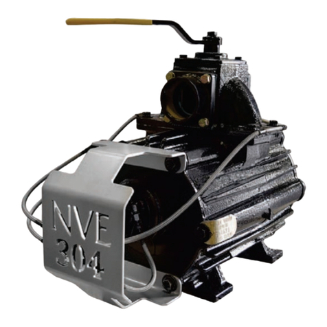
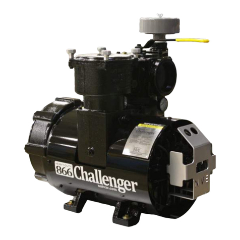
NVE 866 Challenger Series User manual

National Vacuum Equipment
800-253-5500 natvac.com
Owner’s Manual
866 Challenger Rotary Vane Pump

2| 866 Challenger Series www.natvac.com | 800.253.5500
© 2019 National Vacuum Equipment, Inc.
Revision: 8 (Release) August 2019
No part of this manual may be reproduced without the written permission of
National Vacuum Equipment, Inc.
866 CHALLENGER
Owner’s Record
Date of Purchase: _________________________
Purchased from: __________________________
Serial Number: ____________________________
If your pump was manufactured after June 1, 2014,
it contains a NVE manufactured 4 port oil pump.
See pages 12 - 13 for additional information

866 Challenger Series | 3www.natvac.com | 800.253.5500
Counter Clockwise
Rotation
Clockwise
Rotation
IMPORTANT INFORMATION FOR INSTALLING
PUMP
866 CHALLENGER SERIES PUMPS AERIAL VIEW
SHADED AREA MUST BE KEPT CLEAR
FOR SERVICING THE FILTER

4| 866 Challenger Series www.natvac.com | 800.253.5500
CONTENTS
Introduction .................................................................................. 5
General Information�������������������������������������������������������������������������������������������5
Limited Warranty......................................................................... 6
Warranty ��������������������������������������������������������������������������������������������������������������6
Warranty Procedures.................................................................. 8
866 Challenger ............................................................................ 9
Application�����������������������������������������������������������������������������������������������������������9
Pump Specications ������������������������������������������������������������������������������������������9
System Requirements ������������������������������������������������������������������������������������ 10
Drive System ��������������������������������������������������������������������������������������������������� 11
Factory Settings ����������������������������������������������������������������������������������������������� 11
Adjusting Factory Oil Settings������������������������������������������������������������������������ 12
Operating Instructions ........................................................... 14
Normal Operation ������������������������������������������������������������������������������������������� 14
Recommended Lubricant������������������������������������������������������������������������������� 15
Ballast Valve System���������������������������������������������������������������������������������������16
Ballast Valve Troubleshooting������������������������������������������������������������������������16
Adjusting Ballast Valve Opening Level ��������������������������������������������������������� 17
Ballast Valve Rebuilding���������������������������������������������������������������������������������18
Maintenance ���������������������������������������������������������������������������������������������������� 20
Cold Weather Operation��������������������������������������������������������������������������������� 21
Troubleshooting........................................................................ 22
Pump overheats����������������������������������������������������������������������������������������������� 22
Pump uses too much oil��������������������������������������������������������������������������������� 22
Pump doesn’t turn������������������������������������������������������������������������������������������� 22
No vacuum�������������������������������������������������������������������������������������������������������� 23
System Troubleshooting ��������������������������������������������������������������������������������� 23
Making a Vacuum Tester�������������������������������������������������������������������������������� 24
Parts Breakdown......................................................................25
866 Fan Parts List ������������������������������������������������������������������������������������������ 26
866 Liquid Parts List�������������������������������������������������������������������������������������� 30

866 Challenger Series | 5www.natvac.com | 800.253.5500
INTRODUCTION
General Information
About National Vacuum Equipment
Congratulations! You now own a quality vacuum/pressure pump
proudly manufactured in the U.S.A. by National Vacuum Equipment,
Inc. You have not only acquired a superior piece of equipment from a
qualied dealer, you have hired a team of vacuum experts. We stand
ready to work with your dealer to answer your questions and provide you
with the information necessary to keep your equipment in peak working
condition�
Thank you for putting your trust in National Vacuum Equipment.
Our Mission
We are dedicated to the production and wholesale distribution of quality
vacuum system products at a reasonable price, on a timely basis. We
are a “one-stop shop” for manufacturers and distributors of vacuum
equipment.
Our History
National Vacuum Equipment, Inc. was founded in 1980 by Bruce Luoma.
The Company started as a retailer of vacuum pumps. Soon after it
started, the Company secured the rights to exclusive distribution of the
Battioni vacuum pumps in North America. This helped the Company to
evolve into its current status as a wholesale supplier.
To reach the goal of becoming a full service supplier of vacuum
system components, the Company began fabrication of its own line of
componentry, purchased and developed its own line of vacuum pumps,
and began purchasing for resale, various valves and accessories.
Today, NVE has full service machine, fabrication and powder-coating
shops complete with CNC-controlled production equipment designed
for close tolerance work. The company has a highly trained staff, all of
whom are dedicated to quality.

6| 866 Challenger Series www.natvac.com | 800.253.5500
Warranty
National Vacuum Equipment, Inc.
Guarantees that the product it provides is free of manufacturer’s
defects, including materials and workmanship. Properly installed and
maintained product is warranted for a period of one (2) year subject to
the following conditions:
1�A properly completed warranty registration card must be
received by us within 30 days of sale to end user for pump sales
to be considered warrantable. All pumps received for warranty
consideration must retain the original NVE serial number tag.
2�The one (2) year period shall begin the day the product is shipped
from our warehouse, unless we are provided with an authentic copy
of the original resale invoice, in which case the one (2) year period
shall begin at such invoice date.
3�The covered product must be used in an application for which it was
intended. We do not recommend our product for particular uses or
applications.
4�Vane breakage, or damage caused by vane breakage, is not
warrantable�
5�Damage caused by improper use or lack of proper maintenance is
not warrantable�
LIMITED WARRANTY
866 Challenger

866 Challenger Series | 7www.natvac.com | 800.253.5500
6�Manufacturer’s liability under this or any other warranty, whether
express or implied, is limited to repair of or, at the manufacturer’s
option, replacement of parts which are shown to have been
defective when shipped.
7� Manufacturer’s liability shall not be enforceable for any product
until National Vacuum Equipment, Inc. has been paid in full for such
product�
8�Except to the extent expressly stated herein, manufacturer’s
liability for incidental and consequential damage is hereby
excluded to the full extent permitted by law.
9�Manufacturer’s liability as stated herein cannot be altered except in
writing signed by an ofcer of National Vacuum Equipment, Inc.
The maximum allowable operating vacuum will vary
depending on R.P.M., ambient temperature, altitude and
time running. The basic principle to keep in mind is - faster
R.P.M., higher air temperature and longer run time all equal
more heat in pump. When installing an NVE 866 pump we
recommend a normal R.P.M. of 1000. Other speeds are ok
as long as exhaust gas temperatures read on the supplied
thermometer do not exceed 380 degrees F.
Weights and measurements are for reference only.

8| 866 Challenger Series www.natvac.com | 800.253.5500
Application
Designed for extended operation
• Duty cycle will vary depending on several factors, including altitude,
RPM & ambient temperature�
• The 866 Challenger is a severe duty vacuum pump, designed to be
used in liquid waste pumping systems where extended operation is
desired.
• Proven applications are:
- Oil eld - Septic
- Restaurant Grease - Industrial Waste
Pump Specifications
866 Calculated Flow Data
866 CHALLENGER
Model-Specific
Information
RPM
Pressure (PSI) Free Flow Vacuum (in Hg)
20 15 10 5 0 6 12 15 18 21 27
1150 Hp 44 36 30 23 19 18 22 23 25 26 29
CFM 461
1000 Hp 37 30 24 18 10 14 18 20 22 23 26
CFM 410
900 Hp 33 25 22 16 812 15 17 18 20 23
CFM 352
Note: Ambient temperature, altitude, and a variety of other factors will
affect the values listed above.

866 Challenger Series | 9www.natvac.com | 800.253.5500
System Requirements
High Quality Components
• The 866 Challenger is a high performance vacuum pump and
requires compatible, high quality components as manufactured by
NVE�
Shutoffs
• We recommend the use of NVE Part #: 200-1206-4HB portal/portal
shutoff, and NVE Part #: 216-140-4NPT-C, 14 gallon scrubber/
secondary shutoff.
Final filter
• We also require the use of a nal lter. You can use our remote
mounted lter. (NVE Part #: 220-120-4NPT)
Hose
• Use 4” or larger hose to pump your system. We recommend you use
a hose that can withstand high temperatures and pressures such as
hot tar-asphalt hose.
Pressure relief and vacuum relief valves
• A pressure relief valve (2” or larger) and vacuum relief valve (1.5”
or larger) should also be incorporated into the system between the
vacuum pump and moisture trap.
• Your vacuum pump will potentially produce more pressure than
is safely allowed for you vacuum tank. Consult with your tank
manufacturer to determine the appropriate pressure rating.
• The vacuum relief valve will vary due to factors such as vacuum
pump RPM, ambient temperature, altitude of operation, and should
be set for operating vacuum of 20” Hg.
• Run the pump for 30 minutes with all tank valves closed
monitoring exhaust temperature. The relief valves should be set
to where the pump operates at a maximum temperature of 375
degrees F.
• Extremely hot and humid days will require close monitoring of pump
exhaust temperatures and may limit maximum duty cycle vacuum.
WARNING: The vacuum pump will likely put up far more pressure than
your vacuum pressure tank is designed to withstand. Over pressurizing

10 | 866 Challenger Series www.natvac.com | 800.253.5500
Drive System
• The pump should be mounted on a level, horizontal surface, secured
with Grade 8 fasteners.
• The drive system should be sized to supply the required horsepower
to the pump plus a reserve to insure long life.
• Make certain that all shafts, pulleys or turning parts are properly
guarded�
• Check the ratio of the drive system prior to installation to verify that
the pump will be turning at the proper speed and direction.
• Immediate engagement at working rpm for any rotating equipment
will cause failure or premature wear. It is the responsibility of the
installer and user to ensure the vacuum pump or blower is not being
over torqued at start up.
• The pump should be set up to engage slowly to avoid initial torque
damage�
Direction of Rotation
• The direction of rotation and RPM are marked on the front of the
pump�
• The direction of rotation required by your drive system should be
determined prior to ordering the pump.
• If during assembly of your unit you nd you need the opposite
rotation, call NVE for instructions.
Factory Settings
• The automatic lubrication pumps are set at the factory during pump
testing and should require no further adjustment during pump
installation. The pump should consume 12-14 oz of oil per hour if
operated at 900 RPM�
• It is the responsibility of the installer to ensure proper vacuum/

866 Challenger Series | 11www.natvac.com | 800.253.5500
Oil Pump Flow Rate Adjustment Procedures
1. Remove oil pump cap (3/32 hex).
� Ensure o-ring stays intact.
3/32 Hex
2. Move cam so adjustment screws
� are resting on lower ats
Upper Flat
Lower Flat
3. Hold adjustment screw (9/64 hex or at
� head screw) while loosening jam nut
� 1/4” wrench). Spin jam nut all the way
� up to the head.
Adjustment
Screw 9/64
Hex or Flat
Head Screw
Depending
on Unit
Jam Nut
4. Tighten adjustment screw (CW) until
� it seats on the cam. (Do not force!
Seated
Against Flat
of Cam
5. Back the screw off the desired amount
of turns (CCW) - 5 turns if running at
900 RPM
Tip: More turns out equals less oil ow.
� Fewer turns out equals more oil ow.
6. Retighten jam nut while holding
� adjustment screw.
7. Repeat process for other
� adjustment screw.
8. Reassemble cover onto pump
� assuring o-ring does not fall out of
groove, and springs are located over
� adjustment screws
Springs
Located Over
Screws
If oil pump requires further adjustment, the
rule is 1/2 turn CW = 1 oz/ hr higher oil ow.
Jam Nut Tight
Against Piston
O-ring
Seated in
Groove

12 | 866 Challenger Series www.natvac.com | 800.253.5500
Adjusting Factory Oil Settings Continued
Turns From Bottom Ounces Per Hour
7�5 6
7�25 7
7 8
6�75 9
6�5 10
6 11
5�5 12
5 13
4�75 14
4�5 15
4�25 16
NVE 4 Port Oil Pump Adjustment Rate Chart
Tested at 1100 RPM

866 Challenger Series | 13www.natvac.com | 800.253.5500
866 Challenger
Normal Operation
Oil Reservoir
• Check oil reservoir daily and ll as required.
• Drain and clean periodically depending on service.
• Clean the ballast air lter with diesel fuel regularly
Recommended RPM
• The 866 vacuum/pressure pump operates between 900 and 1200
RPM. Lower RPM result in less airow (352 CFM at 900 RPM) but
will result in higher working vacuum level (27 “ Hg at 900 RPM).
Higher RPM will result in increased air ow (461 CFM at 1150 RPM)
and less working vacuum (23 “ Hg at 1150 RPM). RPM should be
set to meet the needs and expectations of the operator. Vacuum
relief valves should be adjusted for a maximum working exhaust
temperature of 375 degrees Fahrenheit. Pressure relief valves
should be adjusted to meet the tank manufacturer specications.
• Too low of an RPM can cause the vanes to clatter (inconsistent
contact with the housing) causing wear.
Suction Valve
• To operate the suction valve, move the handle in the
appropriate direction for either vacuum or pressure;
center is neutral.
Vacuum Levels
• Do not operate your pump for extended periods of time at vacuum
levels which cause the pump exhaust gas temperature to exceed
375 degrees Fahrenheit.
OPERATING INSTRUCTIONS

14 | 866 Challenger Series www.natvac.com | 800.253.5500
Guards
Make certain all guards are in place prior to running your pump.
Think Safety!
Recommended Lubricant
• We recommend that turbine oil be used in our pumps. Turbine oil is
much more resistant to breakdown due to heat than normal motor
oil, thereby avoiding the problems associated with motor oil such as
lacquering and excessive wear.
• NVE ISO 150 Oil is our recommended pump oil for the Challenger
series vacuum pumps. Challenger Vacuum Pump Oil is sold by the
case, six-1 gallon containers of oil per case.

866 Challenger Series | 15www.natvac.com | 800.253.5500
Ballast Valve System
• The Challenger 866 Vacuum Pump features an integral ballast air
cooling system. It works by allowing cooling air to enter the pump
at higher vacuum levels just prior to the exhaust port. This allows
the pump to dissipate the heat produced by friction. The overall
result is cooling of the housing and rotor will no appreciable drop
in vacuum level. At lower vacuums, sufcient air is moving through
the pump to accommodate heat dissipation. The ballast valve
features an integral check system that automatically opens once
a predetermined vacuum level has been reached (usually at 12”
Hg). Inclusion of the ballast system greatly enhances the 866’s duty
cycle. The 866 should never be run for extended periods above 12”
Hg without the allowance of ballast air.
Ballast Valve Troubleshooting
• Ballast valve not opening
- Ballast valve adjustment screw set to open too high
(see next section)
- Clogged ballast air lter
- Loose vacuum line tting/leaking vacuum line
- Vacuum line blockage
- Torn ballast valve diaphragm
(see ballast valve rebuilding section)
- Defective O-Ring on Boss plug in ballast valve cover
• Ballast valve stays open
- Ballast valve adjustment screw set to open too low
(see next section)
- Debris caught in ballast valve plunger
(see ballast valve rebuilding section)
- Worn ballast valve plunger pilot
(see ballast valve rebuilding section)

16 | 866 Challenger Series www.natvac.com | 800.253.5500
Adjusting Ballast Valve Opening Level
The following tools will be required to adjust the ballast valve
opening level:
- 7/32” hex drive
- 1/4” hex drive
- Flat head screwdriver
• Using the 7/32” hex drive, remove the boss plug from the
cover of the ballast valve.
• Using the 1/4” hex drive, remove the locking jam nut.
• The ballast valve opening adjustment screw lies under the
locking jam nut�
• Remove the ballast air lter from the top of the ballast valve.
• Run pump to desired ballast opening vacuum level
(recommend 12” Hg).
• If ballast is not open (and should be), turn adjustment screw CCW
slowly with at-head screwdriver until air just begins to ow.
• If ballast opens before desired vacuum has been reached,
turn adjustment screw CW slowly with at-head screwdriver until
air is just owing.
• Place thumb over adjustment hole and ensure opening
level is accurate.
*Without the boss plug, vacuum chamber is not sealed, thus opening level
may vary slightly.
• If adjustment holds accurate, replace locking jam nut, boss
plug, and the ballast air lter.
BALLAST AIR FILTER
CHECK AIRFLOW HERE
BY FEEL AND/OR NOISE
ADJUSTMENT SCREW
INSIDE STEM
LOCKING JAM NUT
BOSS PLUG

866 Challenger Series | 17www.natvac.com | 800.253.5500
Ballast Valve Rebuilding
If, from the troubleshooting guide shown previously, a ballast valve is
determined to require rebuild, a rebuilding kit can be obtained from NVE.
This kit will include all the components necessary to rebuild the ballast
valve. The ballast valves have been designed to be eld rebuild-able. The
procedure is shown below:
1� Remove the ballast valve vacuum line from the ballast valve cover
(1/2” Wrench).
2� Remove the six socket head bolts from the ballast valve cover.
Caution: The cover will be under slight spring tension
3� Remove cover carefully (spring should stay in cover).
4� Remove plunger assembly from ballast valve.
5� Remove nut from plunger assembly and disassemble.
6� Replace ballast valve diaphragm and the ballast valve protective
gasket and reassemble plunger assembly.
7� Place a small amount of Loc-tite on threads and an mating face of
nut and tighten.
8� Ensure plunger sealing face and internal housing sealing face are
free of burrs.
9� Insert plunger assembly back into ballast valve housing.
10. Place spring in the cover pilot, align JIC tting downward and close
to the pump, and replace cover.
Note: Spring tension will have to be overcome to start bolts
Important: The shorter bolt goes in the 6 o’clock position
11. Tighten bolts evenly.
12. Remove and replace the boss plug in the ballast valve cover.

18 | 866 Challenger Series www.natvac.com | 800.253.5500
Ballast Valve Rebuilding
Ballast Valve Rebuilding_____________________________________________________________
If, from the troubleshooting guide shown previously, a ballast valve is determined to require
rebuild, a rebuilding kit can be obtained from NVE. This kit will include all the components
necessary to rebuild the ballast valve. The ballast valves have been designed to be field rebuild-
able. The procedure is shown below:
1. Remove the ballast valve vacuum line from the ballast valve cover (1/2” Wrench)
2. Remove the six socket head bolts from the
ballast valve cover
Caution: The cover will be under slight spring
tension
3. Remove cover carefully (spring should stay in
cover)
4. Remove plunger assembly from ballast valve
5. Remove nut from
plunger assembly and
disassemble
6. Replace ballast valve diaphragm and the ballast valve
protective gasket and reassemble plunger assembly
7. Place a small amount of Loctite on threads and an mating face
of nut and tighten
8. Ensure plunger sealing face and internal housing sealing face
are free of burrs
9. Insert plunger assembly back into ballast valve housing
10. Place spring in the cover pilot, align JIC fitting downward and close to the pump, and
replace cover
Note: Spring tension will have to be overcome to start bolts
Important: The shorter bolt goes in the 6 o’clock position
11. Tighten bolts evenly
12. Remove and replace the boss plug in the ballast valve cover
*Since adjustment wasn’t altered, ballast valve should retain previous opening level
REMOVECOVER&
SPRING
BALLASTVALVE
DIAPHRAGM
(120-097-004)
BALLASTVALVE
PROTECTIVEGASKET
(120-095-012)
*Since adjustment wasn’t altered, ballast valve should retain
previous opening level

866 Challenger Series | 19www.natvac.com | 800.253.5500
Maintenance
Washing
• Periodically wash the mud and dirt off of your pump as it must be
clean to allow the ns to dissipate heat properly.
Flushing
We recommend periodic ushing of your pump. To do this:
1�Connect the hose to the ush valve located on the side of the inlet
port�
2�Put the end of the hose in a one pint container of diesel fuel. Start
your pump and run as slow as possible.
3�With the 4-way valve in the vacuum position, open the ush valve
and monitor the diesel ow to your pump.
4�When the diesel fuel is gone, switch the 4-way valve to neutral and
run the pump for 2 minutes.
5�Speed the pump up to normal RPM, switch the 4-way valve to
vacuum�
6�Close the valve and remove the hose.
7� Drain oil catch mufer and properly dispose of used oil and ushing
uid.
Checking Vane Wear
We recommend checking vane wear, at a minimum, every 12 months.
• A new vane is ush with the outside diameter of the rotor.
• Remove the plug from the vane check port, insert a clean rod to
rotor O.D., rotate rotor until the rod falls into one of the vane slots. If
the rod falls more than a 1/4” into any of the 6 vane slots, it’s time
to replace the vanes.
• Vanes should be replaced in sets and it is always a good idea to have
an extra set of vanes on hand for emergencies.

20 | 866 Challenger Series www.natvac.com | 800.253.5500
Cold Weather Operation
Confirm pump is not frozen
• Prior to engaging the pump, turn by hand to conrm it is not frozen.
If pump is frozen, thaw it.
• If the pump is frozen, move the truck into a heated building.
Avoid freezing problems
• You can avoid freezing problems by putting a small amount of diesel
fuel into the pump at the end of the day.
VANE ANALYSIS TRACKING SHEET
DATE WEAR (IN) REPLACEMENT? COMMENTS
Other manuals for 866 Challenger Series
1
Table of contents
Other NVE Water Pump manuals
Popular Water Pump manuals by other brands

EBARA
EBARA DMLEU Operating instructions, installation & maintenance manual

SOLARJACK
SOLARJACK SDS installation manual

HNP Mikrosysteme
HNP Mikrosysteme mzr-6359 Ex operating manual

CET
CET PFP-20HPKHL-2D instruction manual

Gianneschi
Gianneschi CP Series operating manual

Edwards
Edwards nEXT 730D instruction manual