nVent RAYCHEM HHS User manual

HHS
Hopper Heating System Installation Instructions
DESCRIPTION
The nVent RAYCHEM Hopper Heating System (HHS) is designed for
use with Electrostatic Precipitator (ESP) hoppers, baghouse hoppers
andmaterial / dust-collector hoppers.
It is highly recommended for all HHS heaters to be used in conjunction
with a temperature control device. These instructions describe the
procedure for installation, storage and handling of HHS heaters.
Carefully follow all directions.
For technical assistance, contact nVent at [email protected]
ADDITIONAL / OPTIONAL MATERIALS REQUIRED
The HHS heater must be installed
correctly to ensure proper operation
and to prevent shock or fire. Read these
important warnings and carefully follow
all the installation instructions.
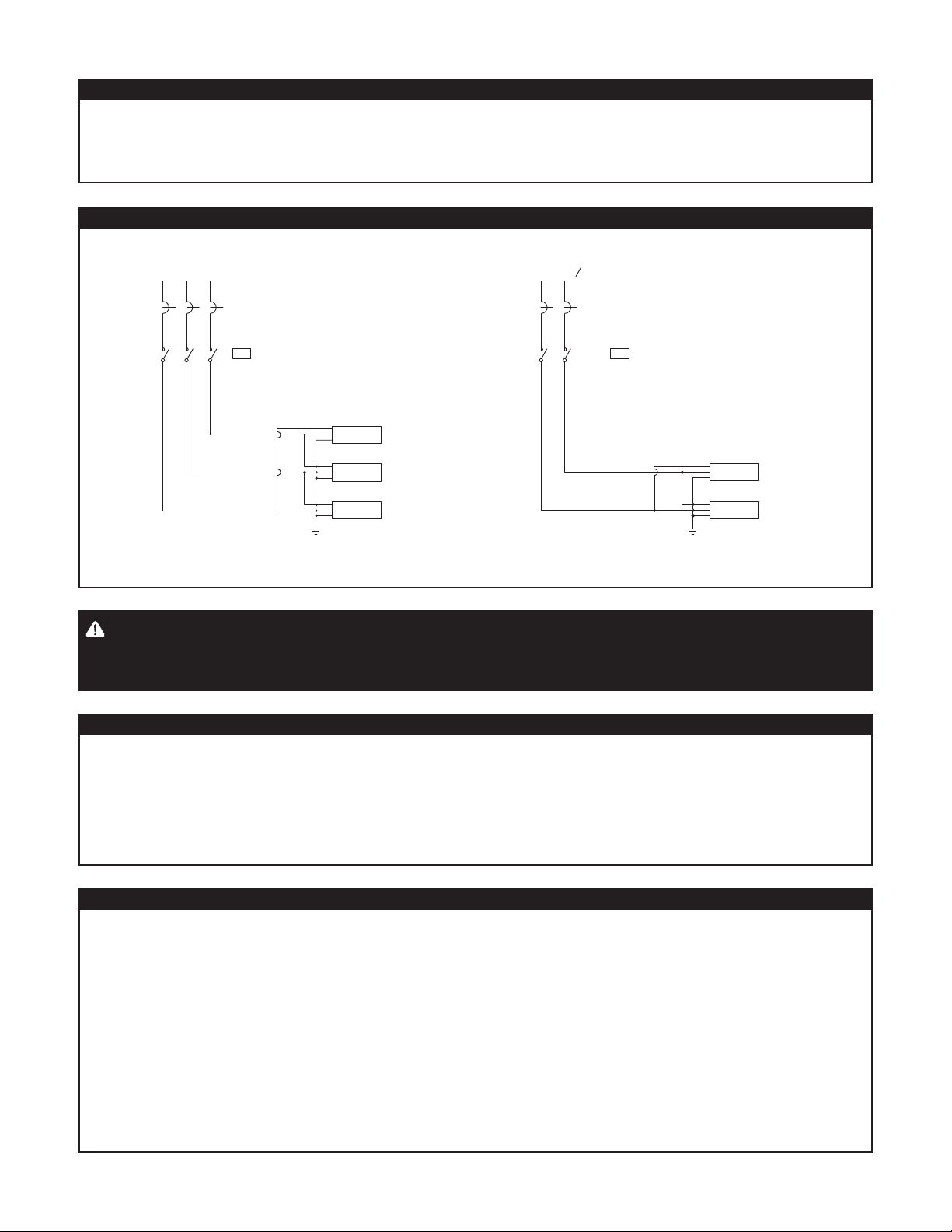
• All electrical wiring must follow
local electrical codes. Ground fault
equipment protection must be used on
each heater branch circuit to minimize
the danger of re if the heater is
damaged or improperly installed
and to comply with nVent design
requirements, agency certications
and national electrical codes.
• Damaged heaters and connections
must be replaced. Do not attempt to
repair or energize if damaged. Only
qualied personnel are allowed to
connect electrical wiring. Disconnect
all supply power at the source before
making any power connections. It is
highly recommended to never operate
heaters without a temperature control
device.
• The end-user is responsible for
providing a suitable disconnecting
device.
• The end-user is responsible for providing
a suitable electrical protection device.
• Final installation / wiring is to be
inspected by the authority who has
jurisdiction in the area that the heater
is installed.
• Approvals and performance are based
on the use of specied parts only.
Do not use vinyl electrical tape or
substitute parts.
• Read and understand this entire manual
before operating this electric heater.
Leave these installation instructions
with the user for future reference.
• Failure to observe these warnings may
result in personal injury or damage to
the heater.
Read and understand this entire manual before operating or servicing these heaters. Failure to understand how to safely operate these
heaters could result in an accident causing serious injury or death. These heaters should only be operated by qualified personnel and any
individual who has not read and understood all installation instructions is not qualified to install this product. Additional copies of this
manual are available upon request.
WARNING:
WARNING: CAUTION:
Approvals valid only when installed in accordance with
all applicable instructions,codes, and regulations.
Ordinary Locations
• Never handle the heater while it is in operation; always
disconnect the heater from the power source and allow for
proper cooling prior to handling.
• Inspect heater before use.
• If spillage of foreign matter onto the heater occurs,
disconnect from the power source and clean after the heater
is allowed to cool.
• Never operate a heater without an appropriate heat sink.
(Device being heated is considered a heat sink).
• Do not operate the heater above the rated temperature value.
• Fasten the heater to the heated surface using approved
methods only.
• Do not repair damaged or faulty heaters.
• Do not crush or apply severe physical stress on the heater or
lead wire assembly.
• Avoid hazards or unsafe practices which could result in
personal injury or property damage.
LIMITED WARRANTY
nVent offers 1 year limited standard warranty for the RAYCHEM HHS.
SAFETY ALERT SYMBOL
The symbol above is used to call your attention to instructions
concerning your personal safety. It points out important safety
precautions. It means “ATTENTION! Become Alert! Your Personal
Safety is involved!” Read the message that follows and be alert to
the possibility of personal injury.
• Wire strippers
• Cleaning / prep supplies
• Wire ties
• Mounting hardware
• Junction box
• Temperature controller
and sensor
• Silicone RTV
• High-temperature
adhesive tape
• Wrap Wound Heater
(HHS-WWH) for the
Conical Throat
• Insulating material
APPROVALS
HHS PRODUCT SPECIFICATIONS
Power density
Standard wattages up to 4650 W/m²
(3.0 W/in²)
Voltage range (nominal)
120 to 600 VAC
Maximum continuous
exposure / maintenance
temperature
260ºC (500ºF)
Maximum intermittent
exposure temperature
(power off)
538ºC (1000ºF)
Minimum installation
temperature
–20ºC (–4ºF)
Dielectric strength
Up to 2,200 VAC
Power leads 5.0m (16 ft.) long, moisture resistant, high-
temperature stainless steel overbraid with
a standard heater ground wire

2 | nVent.com
HOPPER SURFACE PREPARATION
HHS STORAGE
1. Keep each heater in its original packaging until you are ready
to install it.
2. Store the box in a cool, dry environment.
3. Avoid stacking heavy objects on the box, which could damage
the HHS heater.
4. If any heaters are exposed to moisture, please contact nVent
technical support.
1. Inspect the hopper surface. To provide maximum heat
transfer efficiency, verify the installation area is free of:
• Sharp edges or protrusions (weld splatter, rough
seams, etc.)
• Rust and corrosion
• Grease and oil
• Obstructions, such as instrument lines, electrical wiring
or conduit, hopper support, or reinforcements
2. The heater surface should be clean prior to installing the
heaters.
3. Check that the desired placement of the heater will not cause
damage to the heater through impact shock or by neighboring
moving parts.
HEATER PREPARATION
1. Check for suspected damage to the HHS heater prior to
installation and document any identified damages for
settlement with the delivery service.
2. Verify that all parts are received against the packing list.
3. Confirm voltage / wattage rating of heater is appropriate
for the power supply device or temperature controller as
the heater is designed to work at a specific voltage to heat
properly. For additional information, contact nVent.
4. Confirm that the blanket maximum exposure temperature
rating is suitable for the environment. The temperature of the
internal heating element may run up to 25% higher than the
external surface of the blanket.
5. HHS exposure temperature range: –40ºC to 538ºC
(–40ºF to 1000ºF)
• HHS maximum continuous exposure / maintenance
temperature: 260ºC (500ºF)
• HHS maximum intermittent exposure temperature
(power off): 538ºC (1000ºF)
HHS HANDLING
1. All HHS heaters are usually packaged as one set per hopper.
Utilize the layout drawings to match and position each
respective heater to the correct hopper.
2. To avoid mechanical damage do not lay the heater where it
can be stepped on or struck by tools or equipment.
3. Do not fold, twist or bend the heater unless specified by nVent
as a part of the project specific design requirements.
IMPORTANT: This heater is an electrical device. Handle
it with the same care you would use with any electrical
device and carefully follow these instructions.
Do not install any damaged heaters. If a heater is
damaged, replace the complete heating module and
cold leads.
• Do not immerse the heater in liquid.
• Keep volatile or combustible materials away from
the heater when in use.
• Use the heater only in approved locations.
• Keep sharp metal objects away from the heater.
Failure to observe these warnings may result in
electric shock, risk of re, and personal injury.
DANGER:

nVent.com | 3
HEATER INSTALLATION
1
Position the HHS installation template
(sized to correspond to the respective
heating module) against the hopper
sidewall and using a marking pen, mark
the location of the mounting holes to
the hopper surface. Utilize the System
Drawing to identify the proper placement
location for the heaters on the hopper.
This drawing should be used when wiring
and installing the heaters on the hopper
surface.
If two or more heaters are to be placed in close proximity, care should be taken to ensure the proper fit of all modules. By marking
the outline of each template on the hopper wall, sufficient clearance can be verified prior to welding of the studs. In confined or
restricted access areas, the HHS heater module can also be used as the installation template.
IMPORTANT: M. S. Sheet Steel (painted) template is supplied with each unique HHS heater module size for the individual order as
specied in the BOM.
2
A. Insert the M10 x 25mm Stud into
the Welder
B. Weld Stud to Hopper Wall, per the
stud manufacturer's recommendations
and check each connection for a solid
attachment to the hopper wall.
C. Completed Stud
3
Ensure the hopper surface is clean
before securing the heater to the hopper
wall. Position the correct heater frame to
align with the location of the mounting
holes as marked on the hopper surface
and attach the studs (as indicated in
#2 above). Install the hardware in the
following order: flat washer, ground wire,
lock washer, nut (torqued to 30-40 Nm)
and tighten the 2nd jam nut to secure the
heater in place. (Example as shown is
for capacitive discharge stud welding. If
arc-welding is required then an additional
ferrule is included along with the stud.
For additional hardware information, contact nVent.) Carefully route the lead wires to the junction box and connect to the terminal
strip according to the layout drawing.

4 | nVent.com
CONNECTING TO A POWER SOURCE
The heater must be connected to an external control device and
should be operated with some form of temperature control.
1. Install and connect the primary temperature control device
as shown in the installation instructions. The wiring
schematics provided on the next page are for reference only.
See nVent project specific heater layout and wiring drawings
for actual heater wiring.
2. De-energize all power sources before connecting heaters.
The heater ground is the lead wire with green insulation.
Ensure that the lead wires can reach the distance to the
terminal / junction box.
3. The heater is designed to operate at a specific voltage ±10%.
Refer to the label on the heater for the proper operating
voltage and wattage information. Failure to operate the heater
at the specified voltage could result in overheating of the
heating blanket or the heated surface, or personal injury. Also
note lower-than-rated voltage will result in under-heating.
4. All electrical connections must be made by qualified
personnel and in accordance with all applicable codes
and regulations. Proper Personal Protective Equipment (PPE)
should be utilized during installation. Component approvals
and performance ratings are based on the use of nVent
specified parts only.
5. Ensure the heater is protected by a properly rated circuit
breaker or fuse as specified on the design or installation
drawing.
6. Two lead wires (same color) should be connected to the
power source (or temperature control device) directly, through
a junction box, or to a connector that is mated to a receptacle
connected to the power source. HHS heaters are
non-polarized, allowing either wire to be connected to the
neutral or hot. The third wire (if applicable), designated by
the color green (or a green stripe) should be connected to
the ground wire (as indicated in step #3 on the previous
page).
7. Locate the temperature sensors exactly as per the
project drawings.
CONNECTING TO THE CONDUIT FITTING
1. Measure the distance between the heater NPT connection
and power junction box. Use the standard industry practice to
cut the conduit to the appropriate length.
2. Connect the conduit to the power junction box first.
3. Connect the conduit to the heater "hand tighten only" using
a ½” NPT (M) Pipe Size conduit fitting, 90º clamp type flex
connector and ½" female coupling as required.
4. All conduit must be de-burred prior to the feeding of
electrical wires.
IMPORTANT: Reference H60043 for the separate Wrap
Wound Heater (HHS-WWH) installation instructions.
IMPORTANT: Installation example shown is for Capacitive
Discharge stud welding only. If Arc-welding is required then
contact nVent.
IMPORTANT: The HHS Hopper Heating System heater
must be installed with good contact to the hopper surface.
Inadequate contact may result in lower heater eciency.
It is highly recommended to connect the HHS heater to
an external temperature control device, and it is not
recommended to turn on the heater without a temperature
controller. During installation, heaters should not be left
exposed to rain, snow or moisture. It is recommended to
perform a heating system inspection and the necessary
electrical tests before thermally insulating the heaters.
4
Hopper walls
Insulation
gasket
Corners
and bottom
should be
insulated and
well sealed to
prevent ingress
of ambient air
HHS
Heater
Insulation
Insulation
barrier
The design of the hopper heating system is based on the
transfer of heat into the hoppers via convection and conduction
in the openings between each stiffener. The insulation should
be installed flush with the stiffeners to prevent a “chimney”
effect and to ensure an even distribution of heat. It is also
important that an insulation barrier is located at each stiffener
to eliminate these same effects. A 50 mm minimum air space
is recommended for the HHS heaters. (Reference project
installation details as required for unique applications.)

nVent.com | 5
GROUND FAULT PROTECTION
All HHS heater circuits are required to be protected with a ground fault circuit interrupter (GFCI). This device will minimize the risk of
fire or shorting by shutting off the power to the circuit whenever a significant ground-fault current is detected. Suitable circuit breakers
with ground-fault protection can be purchased through nVent.
CONNECTING HHS HEATERS IN PARALLEL
Power Supply
415V Supply
HHS #1
HHS #2
HHS #3
L2 L3
L1
Power Supply
415V/230V Supply
L2 N
L1
3-WIRE, 3-PHASE WITH CONTACTOR
HHS #1
HHS #2
2-WIRE, PHASE-PHASE / PHASE-NEUTRAL WITH CONTACTOR
HHS SYSTEM CONTINUITY AND ELECTRICAL INSULATION RESISTANCE (MEGGER) TESTS
Continuity of each heater should be checked upon removal from packaging and again after installation. Verify that the measured
resistance in ohms agrees with the value printed on the label (with a +/- 10% measured resistance tolerance at 20ºC). Electrical
insulation resistance (IR) should be checked on each heater unit after installation; measure the resistance between the heater element
lead wires and a nearby ground point (e.g., metal heater cladding or welded stud on the hopper wall) at 500 VDC for 1 minute. All IR
values should be greater than 20 megaohms.
IMPORTANT: Ground fault protection devices, although required are not normally displayed in typical single or parallel
wiring diagrams similar to those shown above. Contactors in the diagrams shown above should be controlled by a temperature
control device.
HHS SYSTEM PERFORMANCE TESTING
This test verifies that the system is working properly.
1. When the heaters and controls are installed and connected to
power, and the hopper surface is thermally insulated, turn the
circuit breaker on.
2. Set the primary temperature control device temperature about
20°C higher than the maintain / ambient temperature. This
action energizes the heaters.
3. Allow the heater(s) to be powered for about five minutes,
then measure the voltage and current. Note these values
in the maintenance log as a reference for future
maintenance checks.
4. Lower the temperature control device set point to ensure
that the heater shuts off.
5. Switch off.
6. Set the primary temperature control device to the desired
set point.

6 | nVent.com
SYMPTOM POSSIBLE CAUSE SOLUTION
1. No heat / No current A. Loss of power (voltage) A. Restore power to the heater circuit (check circuit
breaker and electrical connections). Termina-
tions, if not done properly, can cause EPD-type
breakers to trip unexpectedly
B. Controller set point too low B. Adjust set point
C. Heater “Open” C. Check the resistance measurement between the
two lead wires. If no reading, repair or replace
the heater
D. Controller failure D. Repair the sensor or controller
2. Circuit breaker tripping A. Circuit breaker underrated A. Verify rating of the circuit breaker with respect
to the heater output. If breaker is underrated,
replace the breaker
B. Ground fault B. Check insulation resistance between power
leads and the ground lead of the heater. If the
value is less, replace the heater
3. Low system temperature A. Controller set point too low A. Adjust set point
B. Temperature sensor located too close to
the heater
B. Relocate sensor
C. Wet insulation material and / or insulation thick-
ness is different than designed
C. Replace insulation; increase insulation thickness
(if dry)
D. Low voltage (check at power connection point) D. Adjust voltage to meet design requirements
4. High system temperature A. Controller “on” continuously A. Adjust set point or replace sensor
B. Controller failed with contacts closed B. Replace the temperature controller
HHS SYSTEM MAINTENANCE AND TROUBLESHOOTING
It is the responsibility of the end user to ensure that the final
installation meets all local, state and federal codes and
regulations. Please read this manual prior to contacting
nVent, as this manual is designed to answer the most commonly
asked questions.
If you are unable to identify the problem or need additional
assistance, please contact nVent at
.
Perform a continuity test on each HHS heater at least once a
year. The frequency of inspections and tests should depend
on the severity of the environment and operating conditions.
Where multiple heaters are connected in parallel, disconnect and
individually test each heater.
A performance test should also be done once a year. Check
the temperature control device at that time. Things to look for
include the following:
• Control switching at the proper temperature.
• Signs of corrosion around or near the lead wire
connection point.
• Any mechanical damage to the hopper heater cladding
or heating element.

nVent.com | 7

nVent.com
©2018 nVent. All nVent marks and logos are owned or licensed by nVent Services GmbH or its aliates. All other trademarks are the property of their respective owners.
nVent reserves the right to change specications without notice.
Raychem-IM-H59848-HHSIND-EN-1805
North America
Tel +1.800.545.6258
Fax +1.800.527.5703
Europe, Middle East, Africa
Tel +32.16.213.511
Fax +32.16.213.604
UAE
Tel +971 4 378 1700
Fax +971 4 378 1777
Noida-India
Tel +91 120 464 9500
Fax +91 120 464 9548
Mumbai-India
Tel +91 22 6775 8800/01
Fax +91 22 2556 1491
Table of contents
Other nVent RAYCHEM Industrial Electrical manuals
Popular Industrial Electrical manuals by other brands

GE
GE QuiXtra 630 Assembly and mounting instructions

Murata
Murata GRM0335C1H820FA01 Series Reference sheet

Ravas
Ravas SAFECHECK Installation and user manual

Murata
Murata GJM1555C1H1R5BB01 Series Reference sheet

Murata
Murata GRM1885C2A201JA01 Series Reference sheet

Murata
Murata GRM1885C1H6R5CA01 Series Reference sheet