nvent Schroff 24579-416 User manual

3+1 U CPCI Serial System
User‘s Manual
Product Number:
24579-416/417/418/419/420/421/422/423/424
Doc-No: 63972-349_R1.0 January 2016

Impressum:
Schroff GmbH
Langenalber Str. 96 - 100
75334 Straubenhardt, Germany
The details in this manual have been carefully compiled and
checked - supported by certified Quality Management System
to EN ISO 9001/2000
The company cannot accept any liability for errors or misprints.
The company reserves the right to amendments of technical
specifications due to further development and improvement of
products.
Copyright2018
All rights and technical modifications reserved.
R1.0 January 2016 Initial Release

24579-4xx (CPCI Serial Systems 3+1 U)
R1.0, January 2016 I
1 Safety ....................................................................................................................... 1
1.1 Safety Symbols used in this document.............................................................................. 1
1.2 General Safety Precautions ............................................................................................... 1
1.3 References and Architecture Specifications...................................................................... 2
1.4 Product Definition ............................................................................................................. 2
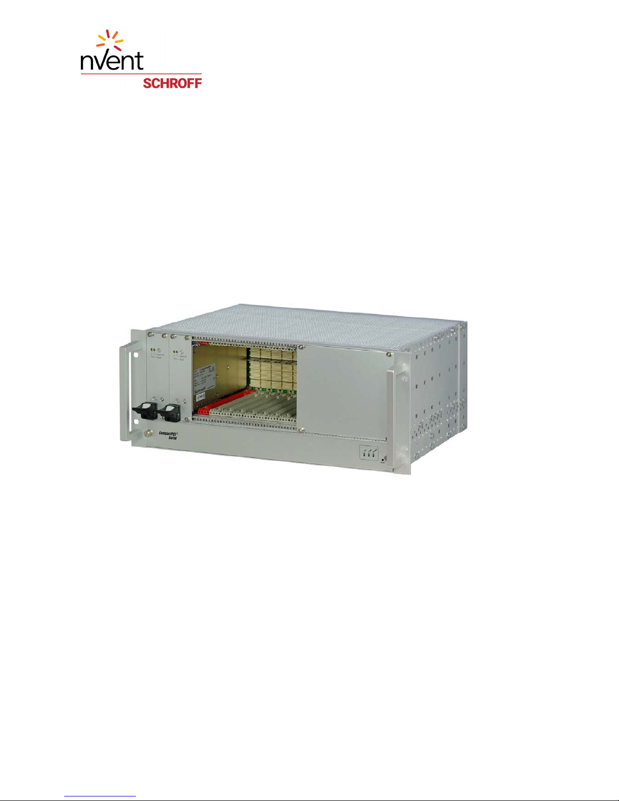
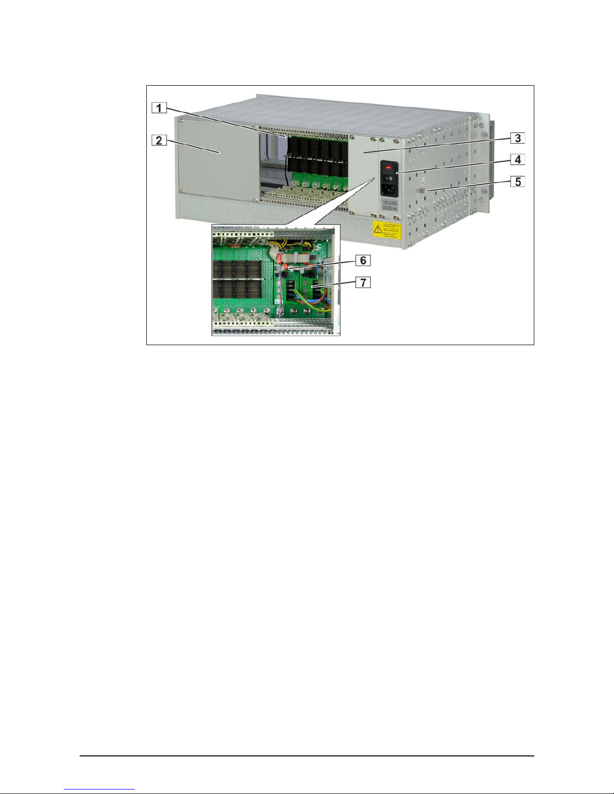
1.5 System Overview............................................................................................................... 3
1.6 Subrack.............................................................................................................................. 4
1.7 Backplane .......................................................................................................................... 5
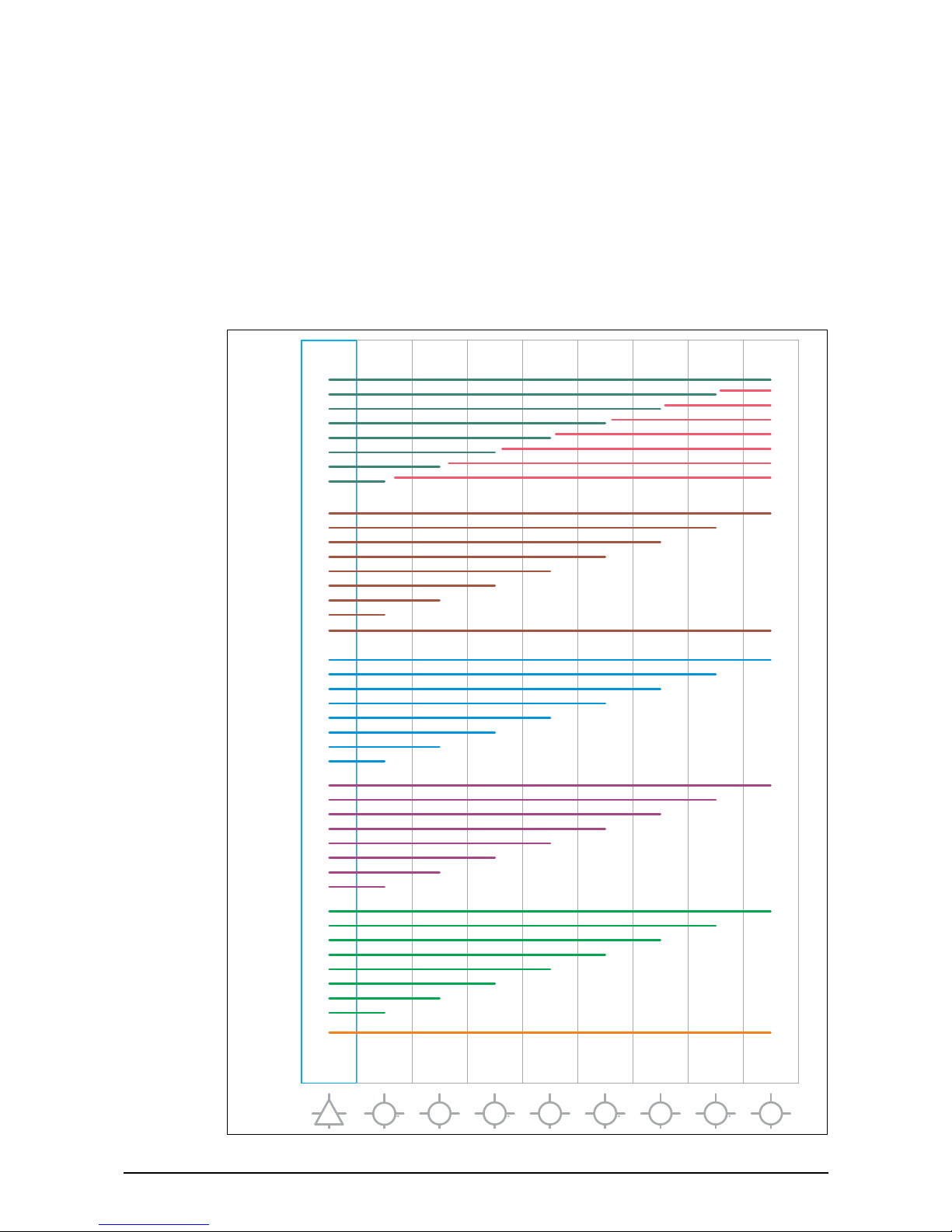
1.8 Topology of a 9 Slot Backplane ......................................................................................... 6
1.9 Power Backplane............................................................................................................... 7
1.10 Power Supply..................................................................................................................... 8
1.10.1 CPCI Plug-In AC Power Supply............................................................................ 9
1.10.2 Grounding/Earthing ........................................................................................... 9
2 Cooling ................................................................................................................... 10
2.1 Air Filter........................................................................................................................... 11
2.2 Airflow............................................................................................................................. 11
3 Installation ............................................................................................................. 12
3.1 General Installation Guidelines ....................................................................................... 12
3.1.1 Unpacking ........................................................................................................ 12
3.1.2 Ensuring Proper Airflow................................................................................... 12
3.2 Rack-Mounting ................................................................................................................ 13
3.3 Initial Operation .............................................................................................................. 13
4 Service.................................................................................................................... 14
4.1 Technical support and Return for Service Assistance ..................................................... 14
4.2 Declaration of Conformity............................................................................................... 14
4.3 Scope of Delivery (24579-421)........................................................................................ 15
4.4 Accessories...................................................................................................................... 15
4.5 Spare Parts ...................................................................................................................... 15
5 Technical Data ........................................................................................................ 16
6 Dimensions............................................................................................................. 17

24579-4xx (CPCI Serial Systems 3+1 U)
II R1.0, January 2016

24579-4xx (CPCI Serial Systems 3+1 U)
R1.0, January 2016 Safety 1
1 Safety
The intended audience of this User’s Manual is system integrators and hardware/software
engineers.
1.1 Safety Symbols used in this document
1.2 General Safety Precautions
• Service personnel must know the necessary electrical safety, wiring and connection
practices for installing this equipment.
• Install this equipment only in compliance with local and national electrical codes.
Hazardous voltage!
This is the electrical hazard symbol. It indicates that there are dangerous voltages inside the
Shelf.
Caution!
This is the user caution symbol. It indicates a condition where damage of the equipment or
injury of the service personnel could occur. To reduce the risk of damage or injury, follow all
steps or procedures as instructed.
Danger of electrostatic discharge!
Static electricity can damage sensitive components in a system. To avoid damage, wear ESD
wrist straps or at regular intervals touch blank enclosure parts.
Warning!
Voltages over 60 VDC can be present in this equipment. This equipment is intended to be
accessed, to be installed and maintained by qualified and trained service personnel only.
This equipment is designed in accordance with protection class 1!
It must therefore be operated only with protective GND/earth connection!.

24579-4xx (CPCI Serial Systems 3+1 U)
2Safety R1.0, January 2016
1.3 References and Architecture Specifications
• User Guide Schroff CPCI Serial Backplanes
Order no.: 63972-333
• User Manual Power Backplanes
Order no.: 63972-334
•User Manual 19“ Power Supply 11098-538
Order no.: 63972-335
1.4 Product Definition
The Schroff CPCI Serial system subracks are available in various backplane and PSU
configurations and consist of:
• A shielded subrack with front and rear card cage for 3 U boards according to CompactPCI
Standard CPCI Serial (CPCI-S.0)
• 1...9 slot 3 U CPCI Serial backplanes with or without Rear I/O
• 1...2 Power Backplanes with SSI-type connector
• 1...2 CPCI Serial plug-in power supplies (300 W) with wide range input and SSI-type con-
nector
• Power input module with IEC 320-C14 connector,mains/line switch, mains/line filter and
fuses
• Fan Trays with or without Fan Control Module (FCM) with 3 axial Fans for the active
cooling of the boards and the power supplies
Available Configurations
The system 24579-421 is described as an example below in this manual.
The system includes:
- 9 slot CPCI Serial backplane with Rear I/O
- 2 power backplanes
- 2 CPCI Serial PSUs (300 W)
- Fan tray with Fan Control Module (FCM2) and Display.
All pictures in this manual may differ from the latest series.
1 x 300 W PSU 2 x 300 W PSU
No Fan Control FCM & Display No Fan Control FCM & Display
Slots w/o Rear I/O with Rear I/O w/o Rear I/O with Rear I/O w/o Rear I/O with Rear I/O w/o Rear I/O with Rear I/O
1On Request On Request On Request On Request On Request On Request On Request On Request
2On Request On Request On Request On Request On Request On Request On Request On Request
3On Request On Request On Request On Request On Request On Request On Request On Request
4On Request On Request On Request On Request On Request On Request On Request On Request
5On Request On Request On Request On Request On Request On Request On Request On Request
6On Request On Request On Request On Request On Request On Request On Request On Request
7On Request On Request On Request On Request On Request On Request On Request On Request
8On Request On Request On Request On Request On Request On Request On Request On Request
924579-416 24579-424 24579-417 24579-423 24579-418 24579-422 24579-419 24579-421

24579-4xx (CPCI Serial Systems 3+1 U)
R1.0, January 2016 Safety 3
1.5 System Overview
Figure 1: Front View
12315801
1PSU 1 6Front Panel 32 U
2PSU 2 7Display
3Fan Tray 89 Slot CPCI-S Backplane
4Power Backplane 1 9Fan Control Module (FCM)
5Power Backplane 2

24579-4xx (CPCI Serial Systems 3+1 U)
4Safety R1.0, January 2016
Figure 2: Rear View
1.6 Subrack
The 4 U chassis is based on the Schroff europacPRO system with EMC shielding. The front card
cage provides 9 CPCI Serial slots.
The lower guide rails of the card cage are equipped with ESD clips.
12315802
1Temperature Sensor 5Ground Terminal
2Front Panel 32 U 6Power Backplane 2
3Front Panel 12 U 7Power Backplane 1
4AC mains/line module

24579-4xx (CPCI Serial Systems 3+1 U)
R1.0, January 2016 Safety 5
1.7 Backplane
Figure 3: Example: 9 Slot Backplane with rear I/O, Systemslot left

24579-4xx (CPCI Serial Systems 3+1 U)
6Safety R1.0, January 2016
1.8 Topology of a 9 Slot Backplane
The CPCI Serial backplane with 9 slots supports the full set of serial links at all slots.
The serial links (SATA/SAS, USB2/3, PCIe) are arranged as a Single Star architecture.
Ethernet is implemented by 4 differential pairs in Single Star routing to support 10/100/1000/
10GBase-T.
More information in the Schroff Backplane manual, order no.: 63972-333
Figure 4: Backplane Topology
1
2
3
4
5
6
7
8
231 456789
GA[3]=GND
GA[2]=GND
GA[1]=GND
GA[0]=GND
GA[3]=GND
GA[2]=GND
GA[1]=GND
GA[0]=OPEN
GA[3]=GND
GA[2]=GND
GA[1]=OPEN
GA[0]=GND
GA[3]=GND
GA[2]=GND
GA[1]=OPEN
GA[0]=OPEN
GA[3]=GND
GA[2]=OPEN
GA[1]=GND
GA[0]=GND
GA[3]=GND
GA[2]=OPEN
GA[1]=GND
GA[0]=OPEN
GA[3]=GND
GA[2]=OPEN
GA[1]=OPEN
GA[0]=GND
GA[3]=GND
GA[2]=OPEN
GA[1]=OPEN
GA[0]=OPEN
1
2
3
4
5
6
7
8
1
2
3
4
5
6
7
8
1
2
3
4
5
6
7
8
2
3
4
5
6
7
8
1
1
1
1
1
1
1
1
1
1
1
1
1
1
1
1
1
1
1
1
1
1
1
1
1
1
1
1
1
1
1
1
1
1
1
1
1
1
1
1
2
2
2
2
2
2
2
7
6
5
4
3
2
1
8
PCIe
SATA
USB 3.0
I2C
ETH
SGPIO
USB 2.0
8x
8x
GA

24579-4xx (CPCI Serial Systems 3+1 U)
R1.0, January 2016 Safety 7
1.9 Power Backplane
The Schroff CompactPCI Serial power backplane accepts a pluggable power supply with SSI-
type connector. The power backplane provides +12 V payload power and for wake-up events
an additional +5 V Standby voltage. More information in the backplane‘s user manual,
order no.: 63972-334
Figure 5: Power Backplane

24579-4xx (CPCI Serial Systems 3+1 U)
8Safety R1.0, January 2016
1.10 Power Supply
The CPCI Serial system is powered by 300 W CPCI Serial plug-in power supplies with wide
range input (100 - 240 VAC). They provide 12 V payload power and 5 V standby power for CPCI
Serial boards.
The power supplies are plugged-in in dedicated slots at the left front side. The power supply
contacts via a SSI-type connector to a Power backplane.
The power input is provided by an AC mains/line module with IEC 320-C14 connector,
integrated mains/line fuses and line filter.
The fuse rating is 10 A slow blow (10AT).
Figure 6: AC mains/line module
Hazardous voltage!
Parts of the power supply may be exposed with hazardous voltage. Always remove mains/
line connector before carry out any assembly work.
Caution!
Your system has not been provided with a AC power cable. Purchase an AC power cable that
is approved for use in your country. The AC power cable must be rated for the product and
for the voltage and current marked on the product's electrical ratings label. The voltage and
current rating of the cable should be greater than the ratings marked on the product.
12309010
1Fuse holder 3AC Connector (IEC320-C14)
2Mains/line switch

24579-4xx (CPCI Serial Systems 3+1 U)
R1.0, January 2016 Safety 9
1.10.1 CPCI Plug-In AC Power Supply
Figure 7: Power Supply
Table 1: Data AC Power Supply
e
More information in the user manual order no.: 63972-335
1.10.2 Grounding/Earthing
Input voltage nominal 100 - 240 VAC
Mains Frequency 50 / 60 Hz
Output (max.) 300 W
Output voltages 5.0
12.0
V
V
-
-
2.5
25
A
A
Ripple < 1 % Peak/Peak
Cooling Requires Airflow > 10 CFM for 300 W Output
Caution!
The unit is designed in accordance with protection class 1! It must therefore be oper-
ated with protective earth/GND connection. Use only a three conductor AC power
cable with a protective earth conductor that meets the IEC safety standards!

24579-4xx (CPCI Serial Systems 3+1 U)
10 Cooling R1.0, January 2016
2 Cooling
The CPCI Serial boards and the power supplies are cooled by forced air convection through
three 12 VDC axial fans located in a hot-swappable fan tray.
2 different fan trays are available:
• Fan Tray with Fan Control Module (FCM), status LEDs and RESET button
(3 fans with 220 m³/h (130 cfm)).
• Fan Tray with constant speed fans
(3 fans with 140 m³/h (85 cfm)).
An air filter is available as an option for both fan trays.
Figure 8: Fan Tray with FCM
The fan speed is determined by a temperature sensor above the card cage. Up to 40 °C the
PWM is 20%, from 40 °C to 60 °C the PWM is increased continously from 20% to 100%.
This control characteristics can be changed by a DIP switch on the FCM. (See user manual,
order no.: 63972-312)
12315803
1Display with Status LEDs 2Fan Control Module
3RESET Push Button (Grounds the PRST# signal)

24579-4xx (CPCI Serial Systems 3+1 U)
R1.0, January 2016 Cooling 11
2.1 Air Filter
An air filter is avalaible as an option. The air filter can be fixed with a mounting frame at the
bottom of the fan tray.
The filter meets the requirements of the Telcordia Technologies Generic Requirements GR-
78-CORE specification.
Figure 9: Fan Tray with Air Filter
2.2 Airflow
Figure 10: Airflow
12315804
1Air Filter with mounting frame
Caution!
To maintain proper airflow, all open slots must be covered with filler panels. The filler panel
should include an airflow baffle that extends to backplane.
12315805

24579-4xx (CPCI Serial Systems 3+1 U)
12 Installation R1.0, January 2016
3 Installation
3.1 General Installation Guidelines
3.1.1 Unpacking
Consider the following when unpacking and storing the system:
• Leave the system packed until it is needed for immediate installation.
• After unpacking the system, save and store the packaging material in case the system
mustbe returned.
If the packaging is damaged and possible system damage is present, report to the shipper and
analyze the damage.
3.1.2 Ensuring Proper Airflow
• Maintain ambient airflow to ensure normal operation. If the airflow is blocked or
restricted, or if the intake air is too warm, an over temperature condition can occur.
• Ensure that cables from other equipment do not obstruct the airflow through the sys-
tems.
• Use filler panels to cover all empty chassis slots. The filler panel should include an airflow
baffle that extends to backplane. The filler panel prevents fan air from escaping out of the
front of an open slot.
Caution!
When opening the shipping carton, use caution to avoid damaging the system.

24579-4xx (CPCI Serial Systems 3+1 U)
R1.0, January 2016 Installation 13
3.2 Rack-Mounting
This subrack system can be installed in 19“ equipment racks. The rack must be accessible
from the front and rear for equipment installation.
Mounting Instructions:
• Ensure that the rack is constructed to support the weight and dimensions of the system.
• Install any stabilizers that came with your equipment rack before mounting or servicing
the system in the rack.
Load the rack from the bottom to the top, with the heaviest system at the bottom, avoid
uneven mechanical loading of the rack.
3.3 Initial Operation
• Ensure that the system has not been damaged during transport, storage or assembly.
•Check the Protective Earth (PE) resistance, should be < 0,1 Ohm.
• Plug-in the boards.
• Cover all open Slots with filler panels.
•Switch on the system.
Warning!
This equipment is intended to be accessed, to be installed and maintained by qualified and
trained service personnel only.
This eqipment is designed in accordance with protection class 1!
It must therefore be operated only with protective GND/earth connection!

24579-4xx (CPCI Serial Systems 3+1 U)
14 Service R1.0, January 2016
4 Service
4.1 Technical support and Return for Service Assistance
We generally recommend to return the complete system. For all product returns and support
issues, please contact your Schroff sales distributor.
We recommend that you save the packing material. Shipping without the original packing
material might void the warranty.
4.2 Declaration of Conformity
SCHROFF CompactPCI systems are developed and manufactured according to EN 60950-1.
SCHROFF CompactPCI systems are not end-products with independent functionality as
described in the definition of the EMC regulations, and therefore a CE marking is not required.
However, when CPCI cards are assembled according to specification, the systems fulfill the
requirements in accordance with EMC Directive 2004/108/EG and Low-voltage Directive
2006/95/EG.
Interference resistance and interference emissions are factors which are heavily influenced
by the type and quantity of CPCI cards used in the system assembly. Through the use of high
quality line filters and EMC optimized enclosure design, SCHROFF offers CPCI systems which
serve as an ideal base for system integrators, which comply with the prescribed limits of EN
6100-6-3 and EN 61000-6-2
The systems are generally equipped with power supplies which possess
CE markings in accordance with EN 60950-1, EN 61000-6-3, EN 61000-6-2).
Before delivery a high-voltage, protective earth and functionality test is carried out on each
individual system.

24579-4xx (CPCI Serial Systems 3+1 U)
R1.0, January 2016 Service 15
4.3 Scope of Delivery (24579-421)
Please order the power cable separately.
4.4 Accessories
4.5 Spare Parts
On request.
Quantity Description
1Shielded europacPRO chassis 4 U / 84 HP with front handles
1CPCI Serial backplane 9 slot 3 U with Rear I/O
2Power backplanes with SSI-type connector
1Front card cage for max. 9 boards 3 U 160 mm deep
IEEE guide rails inc. ESD clips)
1Rear card cage for max. 9 boards 3 U 80 mm deep
IEEE guide rails inc. ESD clips
2300 W CPCI Serial plug-in power supply with input range of 100 VAC to 240 VAC
1Power input module with IEC 320-C14 connector, mains/line switch, mains/line filter and fuses
1Complete AC/DC cabling
1Fan Tray 1 HP with FCM and 3 fans 220 m³/h (140 cfm) each
2Front panel 3 U, 32 HP
1Front panel 3 U, 12 HP
Order No. Description
20848-75x Front panels for Rear I/O Boards, dimensions see catalogue
24579-632 Air filter mounting frame
60713-471 Air filter
20848-7xx Slot covers with front panel and EMC shielding for vacant slots. For dimensions, please see catalogue.
34562-8xx Slot covers for vacant slots. For dimensions, please see catalogue.
24579-03x Printed Circuit Board covers (solder side covers). For dimensions, please see catalogue

24579-4xx (CPCI Serial Systems 3+1 U)
16 Technical Data R1.0, January 2016
5 Technical Data
Table 2: Technical Data
Dimensions
Height 177 mm (4 U)
Width 482.60 mm (19“)
Depth (Card cage) 275 mm
Depth (Overall with handles) 330 mm
Weight
Completely assembled approx. 9 kg
Power Supply
Input Voltage 100 VAC bis 240 VAC
Frequency 50 / 60 Hz
Power input up to 600 W
Ambient Temperature
Operation +0 °C to +50 °C
Storage -40 °C to +85 °C
Humidity
Admissible humidity 30 % to 80 %, non-condensing
EMC, fulfils requirements for:
Transient Emissions EN 61000-6-3
Interference Resistance EN 61000-6-2
Safety
Test voltages according to EN 60950-1 Input - Output:
Input - PE:
Output - PE:
Output - Output:
4,3 kVDC
2,2 kVDC
0,7 kVDC
0,7 kVDC
Shock and vibration: EN 60068-2-6 and EN 60068-2-27
Electromagnetic Shielding
Shielding attenuation typ. 40 dB at 1 GHz if shielded front
panels are used.
This manual suits for next models
8
Table of contents
Popular Desktop manuals by other brands

Moxa Technologies
Moxa Technologies MC-5150-AC Series Quick installation guide

Smooth Fitness
Smooth Fitness LED 15 Computer operating instructions

Intel
Intel Compute Stick STK1A32SC user guide

Advantech
Advantech UNO-2483G User manual and manual

Panasonic
Panasonic CF-W2 Series Service manual

Olivetti
Olivetti M20 user guide