NXS NX200.2 Service manual

POWER AMPLIFIERS
w/ DIGITAL SIGNAL PROCESSORS
Installation Instructions / Owner's Manual
NX200.2 NX400.2
NX400.4 NX1000.1

INTRODUCTION
Congratulations on your purchase of a NXS state-of-the-art power amplifier with digital
signal processing. At NXS Mobile Audio we strive to provide some of the latest
technology tools that make the quest for “the perfect tune” so much easier. Our goal was
to develop technologically advanced amplifiers completely adjustable to the acoustics
of each vehicle.
RECOMMENDATION
A power amplifier’s performance is only as good as its installation. Proper installation
will maximize the system’s overall performance. It is recommended that you have our
product installed by an authorized NXS retailer. However, if you decide to install it
yourself, please carefully read through this manual and take your time to do a quality
installation.
Due to continuing product improvements and possible manual revisions, we
recommend checking our website for latest product information at
www.nxsmobileaudio.com.
WARNING!
Exposure to high power sound system can cause hearing loss or damage. Listening to
your system at loud levels while driving, will impair your ability to hear traffic sounds and
emergency vehicles. Use common sense when listening to your system.
WARNING!
Exposure to high power sound system can cause hearing loss or damage. Listening to
your system at loud levels while driving, will impair your ability to hear traffic sounds and
emergency vehicles. Use common sense when listening to your system.
IMPORTANT! Before making any connections, disconnect the car’s battery until the installation
is completed to avoid possible damage to the electrical system.
Serial # Model #
1
ENGLISH

TAKE CONTROL
The NXS amplifiers feature built-in digital signal processors (DSP). The DSP allows for
control and adjustment of sophisticated features previously found only in mid-to high
end dedicated pre-amplifier equipment. The DSP features are controlled and adjusted
with one of the two following components (sold separately).
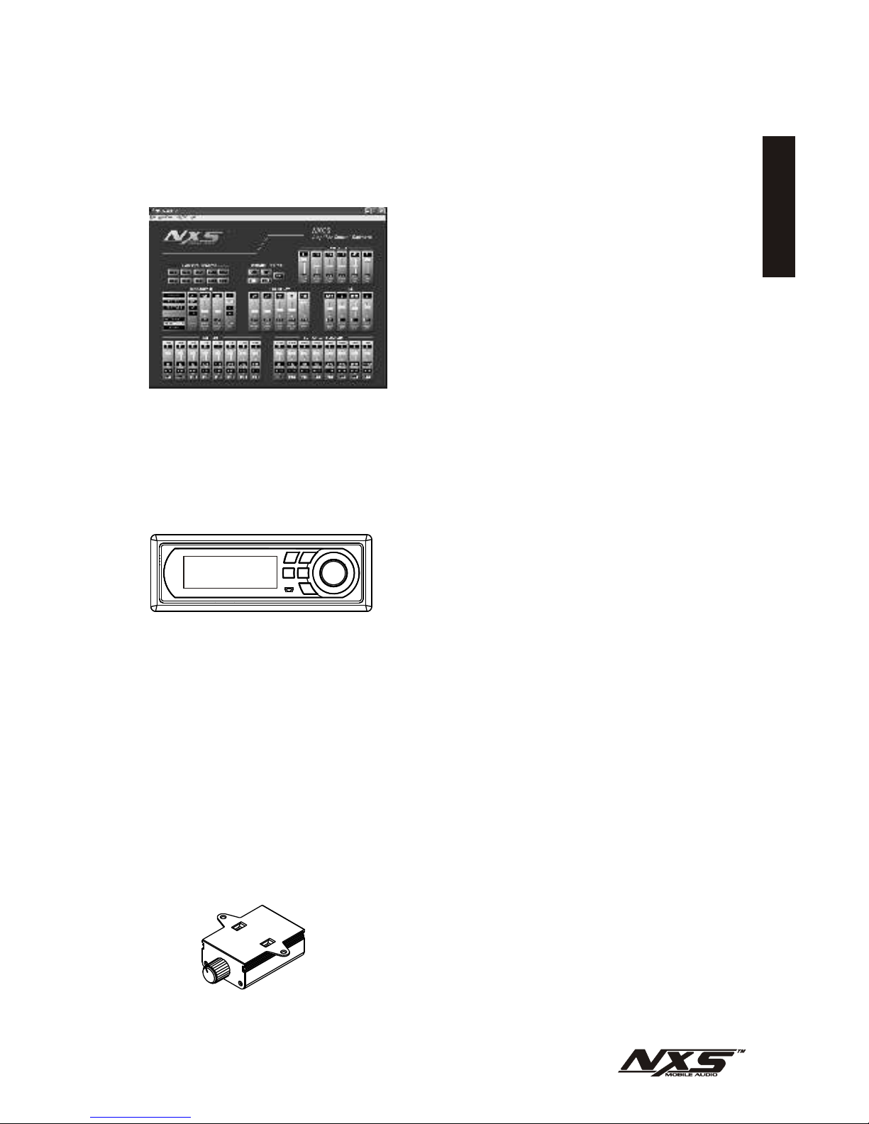
NXLI computer interface and NXCS software:
The NXLI is an control interface which allows
the amplifier's DSP to be controlled by a PC.
The NXLI provides a standard USB plug to
connect to a PC and a RJ11 socket for a cable
connection to the Amplifier's DSP Netlink.
The NXLI is powered by the USB connection
eliminating the need for additional power
connections. This makes the NXLI portable
and simple to connect.
Unlike traditional amplifier installations with the adjustments made on the amplifier in the
back of the car, the NXLI gives the flexibility to position a Laptop PC within the vehicle
while sitting in the listening position making the adjustments real-time. This allows for
ideal calibration of the system including equalization and time delay.
NXLCDC In-Dash Controller:
The NXLCDC is an optional in-dash controller
for users who do not want to use a PC to setup
and control their NXS Amplifiers. Shaped in a
convenient DIN size, the NXLCDC features a
4 line LCD Display, a function selecting scroll
wheel, 4 preset buttons and a 'back' button.
This enables the user to select and adjust different amplifiers connected via DSP Netlink
in the same car. Basic settings like EQ, Gain, Sub-woofer level and Crossover can be
selected and adjusted.
The 4 presets on the NXLCDC can be programmed to recall up to 4 individual
configurations saved to the NXLCDC. The user can easily toggle configurations biased
toward 'classical' vs 'techno' music for instance.
There is also a Mini-USB PC computer input connection at the front of the controller.
This is to allow PCs with the NXCS software installed the convenience of connecting
and controlling the amps through the NXLCDC instead of having to run additional
cables.
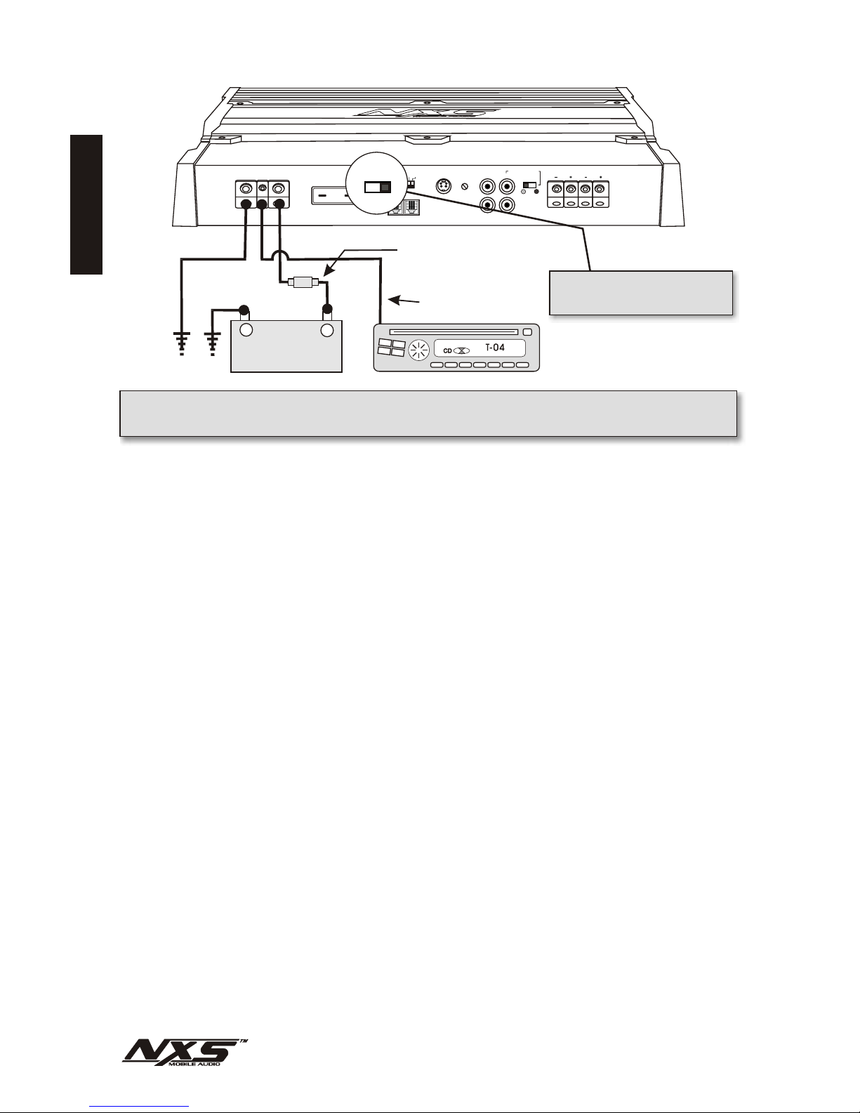
NXLC Remote Level Control:
The NXLC is a remote level control that gives hands-
on-control over the amplifier(s) output level. The
NXLC operates through the amplifier’s DSP Netlink
connection and features an intelligent circuit
allowing you to select which amplifier and/or
channels you would like to control remotely.
Additionally, only one remote is needed to control
ENGLISH
2

SAFETY PRECAUTIONS
Fuse amplifier’s power wire at the battery.
Be sure to fuse the power wire within 6” of the car's battery. This will protect the car's
battery in case of a short circuit between the power amplifier and battery. THIS IS A
MUST, the amplifier's built-in fuse will only protect the power amplifier not the car's
battery!
Use high grade wire connectors.
To ensure maximum power transfer and secure safe connections, it is recommended to
use high grade barrier spades (for connection at amplifier) and terminal rings (for
connection at battery).
Do not run any wires underneath vehicle.
Exposed wires have a chance of being cut or damaged. It is best to run all wires through
the vehicle under the carpet and/or side panels. This lends to a cleaner installation and
less risk of damage.
Use caution when mounting amplifier.
Remember there are many electrical wires, gas lines, vacuum lines, brake lines as well
as a gas tank in the automobile. Make sure you know where they are when mounting
the amplifier to avoid puncturing lines, shorting wires or drilling holes in the gas tank.
Run signal wires away from electrical wires.
To avoid possibility of induced noise from the car's electrical system (i.e. popping noises
or engine noise), run wires away from the car's electrical wiring.
Make all ground wires as short as possible and at the same point.
In order to reduce the chance of ground loops (i.e. engine noise), make the grounding
wire as short as possible to reduce the wire's resistance. Also, when using multiple
components, make sure all units are grounded at the same point.
Avoid sharp edges when running the wires.
To avoid the possibility of power, signal or speaker shorts, be careful not to allow the
amplifier’s wires to come in contact with sharp edges. Use a grommet to protect the wire
when running through the fire wall .
ENGLISH
3

FEATURES AND BENEFITS
Digital Signal Processor
Built-in Digital Signal Processor that can be electronically controlled by the NXLCDC,
NXLI or NXCS (Sold Separately). The processor features the adjustment of gain, X-
over, tone, time delay, equalization.
DC Offset Protection
This circuit protects the output of the amplifier against DC voltage. If for some reason
DC voltage is detected at the output stage, the amplifier will shut down protecting the
speakers from direct current.
Short Circuit Protection
The circuit protects the amplifier from damage due to a short found in the speakers or
wiring. If one of the speakers or its wiring comes in contact with ground, the amplifier will
shut down. To resume normal operation, correct the problem and turn the head unit off,
then back on. The amplifier will reset and play again.
Thermal Protection
To protect the amplifier circuitry against damage caused by prolonged exposure to high
temperatures, a thermal protection circuit is activated if the amplifier reaches
excessively high operating temperature. Once the thermal circuit is activated, the
amplifier will shut down to cool off. The amplifier will automatically turn back on once it
cools down to a safe operating temperature.
Power / Protect Indicator
The power LED Illuminates blue when the amplifier is on and receiving power. The
protect LED Illuminates red when the amplifier has gone into protection mode.
Power Bridge Technology (NX1000.1)
NXS’ Power Bridge technology gives you the flexibility to combine the power of two
NX1000.1 amplifiers to double the output power into one speaker load.
High Level Input
High Level inputs have been included to connect the amplifier to a radio without low-
level outputs (i.e. factory radio).
RemoteAuto Sensing for High Level Input
For added convenience when connecting to factory installed radio’s, the high level input
has a ‘Remote Auto Sensing” circuit allowing the amplifier to turn on when it receives
signal from the radio.
4
ENGLISH

Line Out (NX200.2, 400.2 & 400.4)
One set of full range line outputs have been provided for convenient connection to
additional amplifiers in the system.
Power Fusing
This protects the amplifier against short circuits and excessive current.
Remote Turn-on
Automatically turns amplifier on when connected to the head unit's remote output. The
amplifier will turn on and off with the head unit to save current consumption. This control
also operates the reset circuit for the amplifier's protection. It must be connected with
the head unit in order to reset protection circuits.
Adjustable Input Sensitivity
Allows you to fine-tune the level matching between your source and the power amplifier.
5
ENGLISH

MOUNTING LOCATION
Before you start the installation, it will be necessary to find a mounting location for the
amplifier. Find a location in which the amplifier will receive adequate ventilation in order
to dissipate the heat it develops during operation. Two popular mounting locations are
in the trunk or under the seat.
Select the location in which you wish to mount the amplifier. Use caution when
mounting amplifier, there are many wires, gas lines, vacuum lines, brake lines as well as
a gas tank in the automobile. Make sure you know where they are when mounting the
amplifier to avoid puncturing lines, shorting wires or drilling holes in the gas tank. Once
you are ready, use a pencil to mark the mounting holes in the bottom panel. After you
have marked the locations of the holes move amplifier out of the way and drill small
starter holes to make the tapping screws easier to install. Use provided screws to
tighten down the amplifier.
HIGH LEVEL
CH1&2
NX400.4
CH3&4
MAXMIN
INPUT
LEVEL
INPUT CH3CH1
CH4CH2
OUTPUT
ON
OFF
L
R
DSP NETLINK
IN OUT
8A4 2 1/2
13/4
PRIMARYAMP
ADDRESS
LEVEL
CONTROL
MULTI-AMP
ADDRESS REMOTE
AUTO SENSING
ON OFF
SPEAKERS
BRIDGED
CH2CH1 CH3
BRIDGED
PRT
PWR
CH4
FUSE
60A
POWER
+12V REM GND
6
ENGLISH

POWER BRIDGE
POWER
REMGND +12V
FUSE
REMOTE
AUTO SENSING
ON
DSP NETLINK
IN OUT
8A
4 2 1
PRIMARY AMP
ADDRESS
MULTI-AMP
ADDRESS
OFF
HIGH
LEVEL
ON
OFF
SW
LEVEL
CONTROL INPUT
LEVEL
MIN MAX
INPUT
L
R
IN
OUT
PRT
MASTER
MODE
SLAVE
PWR
SPEAKER
NX1000.1
100A
POWER CONNECTIONS (NX1000.1)
IMPORTANT! Before making any connections, disconnect the car’s battery until
the installation is completed to avoid possible damage to the electrical system.
CAR BATTERY
+12V
--
++
RADIO'S REMOTE
TURN-ON OUTPUT
“REMOTE AUTO SENSING” SWITCH
MUST BE IN THE “OFF” POSITION
FOR THE AMPLIFIER TO TURN ON
IN-LINE POWER FUSE
MOUNTED WITHIN 6"
FROM BATTERY RECOMMENDED
GROUND
(NOT PROVIDED)
Connect the amplifier to the car's battery.
At times, the amplifier will need to draw large levels of current that cannot be provided by
any circuit in the car's fuse box. We recommend using a 4 gauge power wire for your
connections depending on the amplifier and length of the wire. Strip one end of the wire
and connect to the terminal on the amplifier marked “+12V”. Loosen the set screw on
the terminal and insert wire and tighten. Use caution to make sure no stray wire strands
come in contact with surrounding terminals causing short circuits. Run the wire directly
to the positive terminal of the car's battery. Make sure to use an in-line fuse within 6” of
the car's battery to protect the electrical system and amplifier against short circuits
and/or power surges.
Connect the ground terminal of the amplifier to the car's chassis.
For the ground connection, use a 4 gauge wire (black) to connect to the terminal marked
“GND” and then connect it to the car's chassis. Try to keep the length of the cable as
short as possible, preferably less than 6". Make sure that the point on the car where the
connection is to be made is free of paint and dirt.
Connect the remote terminal of the amplifier to a switchable +12V source.
Please note: If you intend to use the high level inputs for your signal connections, we
provide a “Remote Auto Sensing” feature that will automatically turn-on the amplifier
when the high level inputs sense input signal. Please skip this step and see page 10.
This connection allows the amplifier to be turned on and off with the power control of the
radio. If the radio has a REMOTE output terminal, connect it to the amplifier's terminal
marked “REM” (using a 16 gauge wire or heavier). Now when the radio is turned on, the
amplifier will automatically turn on. When using this wire, the “REMOTE AUTO
SENSING” switch should be in the “OFF” position.
7
ENGLISH

50A
DSP NETLINK
IN OUT
MAX
POWER
+12V REM GND
SPEAKERS
PWR
PRT
LR
FUSE
BRIDGED
INPUT
L
OUTPUT
R
HIGH
LEVEL INPUT
LEVEL
MIN
L
R
NX400.2
REMOTE
AUTO SENSING
PRIMARYAMP
ADDRESS
MULTI-AMP
ADDRESS
LEVEL
CONTROL
ON
ON
OFF
OFF 84 2 1 A SW
POWER CONNECTIONS (NX200.2, 400.2 & 400.4)
IMPORTANT! Before making any connections, disconnect the car’s battery until
the installation is completed to avoid possible damage to the electrical system.
CAR BATTERY
+12V
--
++
RADIO'S REMOTE
TURN-ON OUTPUT
“REMOTE AUTO SENSING” SWITCH
MUST BE IN THE “OFF” POSITION
FOR THE AMPLIFIER TO TURN ON
IN-LINE POWER FUSE
MOUNTED WITHIN 6"
FROM BATTERY RECOMMENDED
GROUND
(NOT PROVIDED)
Connect the amplifier to the car's battery.
At times, the amplifier will need to draw large levels of current that cannot be provided by
any circuit in the car's fuse box. We recommend using a 4 or 8 gauge power wire for
your connections depending on the amplifier and length of the wire. Strip one end of the
wire and connect to the terminal on the amplifier marked “+12V”. Loosen the set screw
on the terminal and insert wire and tighten. Use caution to make sure no stray wire
strands come in contact with surrounding terminals causing short circuits. Run the wire
directly to the positive terminal of the car's battery. Make sure to use an in-line fuse
within 6” of the car's battery to protect the electrical system and amplifier against short
circuits and/or power surges.
Connect the ground terminal of the amplifier to the car's chassis.
For the ground connection, use a 4 or 8 gauge wire (black) to connect to the terminal
marked “GND” and then connect it to the car's chassis. Try to keep the length of the
cable as short as possible, preferably less than 6". Make sure that the point on the car
where the connection is to be made is free of paint and dirt.
Connect the remote terminal of the amplifier to a switchable +12V source.
Please note: If you intend to use the high level inputs for your signal connections, we
provide a “Remote Auto Sensing” feature that will automatically turn-on the amplifier
when the high level inputs sense input signal. Please skip this step and see page 10.
This connection allows the amplifier to be turned on and off with the power control of the
radio. If the radio has a REMOTE output terminal, connect it to the amplifier's terminal
marked “REM” (using a 16 gauge wire or heavier). Now when the radio is turned on, the
amplifier will automatically turn on. When using this wire, the “REMOTE AUTO
SENSING” switch should be in the “OFF” position.
50A
DSP NETLINK
IN OUT
MAX
POWER
+12V REM GND
SPEAKERS
PWR
PRT
LR
FUSE
BRIDGED
INPUT
L
OUTPUT
R
HIGH
LEVEL INPUT
LEVEL
MIN
L
R
NX400.2
REMOTE
AUTO SENSING
PRIMARY AMP
ADDRESS
MULTI-AMP
ADDRESS
LEVEL
CONTROL
ON
ON
OFF
OFF 84 2 1 A SW
POWER CONNECTIONS (NX200.2, 400.2 & 400.4)
IMPORTANT! Before making any connections, disconnect the car’s battery until
the installation is completed to avoid possible damage to the electrical system.
CAR BATTERY
+12V
--
++
RADIO'S REMOTE
TURN-ON OUTPUT
“REMOTE AUTO SENSING” SWITCH
MUST BE IN THE “OFF” POSITION
FOR THE AMPLIFIER TO TURN ON
IN-LINE POWER FUSE
MOUNTED WITHIN 6"
FROM BATTERY RECOMMENDED
GROUND
(NOT PROVIDED)
Connect the amplifier to the car's battery.
At times, the amplifier will need to draw large levels of current that cannot be provided by
any circuit in the car's fuse box. We recommend using a 4 or 8 gauge power wire for
your connections depending on the amplifier and length of the wire. Strip one end of the
wire and connect to the terminal on the amplifier marked “+12V”. Loosen the set screw
on the terminal and insert wire and tighten. Use caution to make sure no stray wire
strands come in contact with surrounding terminals causing short circuits. Run the wire
directly to the positive terminal of the car's battery. Make sure to use an in-line fuse
within 6” of the car's battery to protect the electrical system and amplifier against short
circuits and/or power surges.
Connect the ground terminal of the amplifier to the car's chassis.
For the ground connection, use a 4 or 8 gauge wire (black) to connect to the terminal
marked “GND” and then connect it to the car's chassis. Try to keep the length of the
cable as short as possible, preferably less than 6". Make sure that the point on the car
where the connection is to be made is free of paint and dirt.
Connect the remote terminal of the amplifier to a switchable +12V source.
Please note: If you intend to use the high level inputs for your signal connections, we
provide a “Remote Auto Sensing” feature that will automatically turn-on the amplifier
when the high level inputs sense input signal. Please skip this step and see page 10.
This connection allows the amplifier to be turned on and off with the power control of the
radio. If the radio has a REMOTE output terminal, connect it to the amplifier's terminal
marked “REM” (using a 16 gauge wire or heavier). Now when the radio is turned on, the
amplifier will automatically turn on. When using this wire, the “REMOTE AUTO
SENSING” switch should be in the “OFF” position.
8
ENGLISH

50A
DSP NETLINK
IN OUT
MAX
POWER
+12V REM GND
SPEAKERS
PWR
PRT
LR
FUSE
BRIDGED
INPUT
L
OUTPUT
R
HIGH
LEVEL INPUT
LEVEL
MIN
L
R
NX400.2
REMOTE
AUTO SENSING
PRIMARYAMP
ADDRESS
MULTI-AMP
ADDRESS
LEVEL
CONTROL
ON
ON
OFF
OFF 84 2 1 A SW
POWER BRIDGE
POWER
REMGND +12V
FUSE
REMOTE
AUTO SENSING
ON
DSP NETLINK
IN OUT
8A
4 2 1
PRIMARY AMP
ADDRESS
MULTI-AMP
ADDRESS
OFF
HIGH
LEVEL
ON
OFF
SW
LEVEL
CONTROL INPUT
LEVEL
MIN MAX
INPUT
L
R
IN
OUT
PRT
MASTER
MODE
SLAVE
PWR
SPEAKER
NX1000.1
100A
SIGNAL CONNECTIONS
Connect the RCA output of the head unit (AM/FM cassette player, CD, or DAT) to
the RCAinput terminals of the amplifier.
To make these connections, we recommend high quality RCA cables, which are
available at your local car audio retailer. Run signal wires away from electrical wires to
avoid possibility of induced noise from the car's electrical system (i.e. popping noises or
engine noise). Please note that when making these connections the signal inputs
correspond with the speaker outputs.
LL
LL
LL
RR
Optional full range output
for additional amplifiers in
the system.
RR
RR
NX1000.1 CONNECTIONS NX200.2 & NX400.2 CONNECTIONS
The NX400.4 allows for two or four channel input configurations. This gives the
flexibility of using only two channels of input and the amplifier automatically divides the
signal internally for four channels of output (Non Fading). The four channel input
configuration offers normal independent operation allowing for front and rear fading
capability through the head unit.
HIGH LEVEL
CH1&2
NX400.4
CH3&4
MAXMIN
INPUT
LEVEL
INPUT CH3CH1
CH4CH2
OUTPUT
ON
OFF
L
R
DSP NETLINK
IN OUT
8A4 2 1/2
13/4
PRIMARY AMP
ADDRESS
LEVEL
CONTROL
MULTI-AMP
ADDRESS REMOTE
AUTO SENSING
ON OFF
SPEAKERS
BRIDGED
CH2CH1 CH3
BRIDGED
PRT
PWR
CH4
FUSE
60A
POWER
+12V REM GND
LL
RR
NX400.4 CONNECTIONS
USING TWO CHANNEL INPUT
LL
RR
Optional full range output
for additional amplifiers in
the system.
HIGH LEVEL
CH1&2
NX400.4
CH3&4
MAXMIN
INPUT
LEVEL
INPUT CH3CH1
CH4CH2
OUTPUT
ON
OFF
L
R
DSP NETLINK
IN OUT
8A4 2 1/2
13/4
PRIMARY AMP
ADDRESS
LEVEL
CONTROL
MULTI-AMP
ADDRESS REMOTE
AUTO SENSING
ON OFF
SPEAKERS
BRIDGED
CH2CH1 CH3
BRIDGED
PRT
PWR
CH4
FUSE
60A
POWER
+12V REM GND
LL
RR
LL
RR
Optional full range output
for additional amplifiers in
the system.
LL
RR
NX400.4 CONNECTIONS
USING FOUR CHANNEL INPUT
9
ENGLISH

NX200.2 NX400.2 & NX1000.1 CONNECTIONS:
FLOATING GROUND RADIO (MOST COMMON TYPE)
High Level inputs have been included to connect the amplifier to a radio without low-
level outputs (i.e. factory radio). This connection will allow you to connect directly to the
speaker output of the radio without the need of an external adapter.
For added convenience when connecting to factory installed radio’s, the high level input
has a ‘Remote Auto Sensing” circuit allowing the amplifier to turn on when it receives
signal from the radio.
HIGH LEVEL CONNECTIONS (OPTIONAL)
POWER BRIDGE
POWER
REMGND +12V
FUSE
REMOTE
AUTO SENSING
ON
DSP NETLINK
IN OUT
8A
4 2 1
PRIMARY AMP
ADDRESS
MULTI-AMP
ADDRESS
OFF
HIGH
LEVEL
ON
OFF
SW
LEVEL
CONTROL INPUT
LEVEL
MIN MAX
INPUT
L
R
IN
OUT
PRT
MASTER
MODE
SLAVE
PWR
SPEAKER
NX1000.1
100A
REMOTE
AUTO SENSING
ON OFF
RIGHT +RIGHT +
RIGHT +RIGHT +
RIGHT -RIGHT -
RIGHT -RIGHT -
LEFT -LEFT -
LEFT -LEFT -
LEFT +LEFT +
LEFT +LEFT +
WHITEWHITE
WHITE (CH3+)WHITE (CH3+)
GRAYGRAY
GRAY (CH4+)GRAY (CH4+)
WHITE/BLACKWHITE/BLACK
WHITE/BLACK (CH3 -)WHITE/BLACK (CH3 -)
GRAY/BLACKGRAY/BLACK
GRAY/BLACK (CH4-)GRAY/BLACK (CH4-)
HIGH LEVEL
CH1&2
NX400.4
CH3&4
MAXMIN
INPUT
LEVEL
INPUT CH3CH1
CH4CH2
OUTPUT
ON
OFF
L
R
DSP NETLINK
IN OUT
8A4 2 1/2
13/4
PRIMARY AMP
ADDRESS
LEVEL
CONTROL
MULTI-AMP
ADDRESS REMOTE
AUTO SENSING
ON OFF
SPEAKERS
BRIDGED
CH2CH1 CH3
BRIDGED
PRT
PWR
CH4
FUSE
60A
POWER
+12V REM GND
RIGHT +RIGHT +
RIGHT -RIGHT -
LEFT -LEFT -
LEFT +LEFT +WHITE (CH1+)WHITE (CH1+)
GRAY (CH2+)GRAY (CH2+)
WHITE/BLACK (CH1-)WHITE/BLACK (CH1-)
GRAY/BLACK (CH2-)GRAY/BLACK (CH2-)
NX400.4 CONNECTIONS:
FLOATING GROUND RADIO (MOST COMMON TYPE)
The Remote Auto Sensing
Switch is in the “ON” position.
REMOTE
AUTO SENSING
ON OFF
The Remote Auto Sensing
Switch is in the “ON” position.
RCA Plugs
(Included)
The NX400.4 allows for 2 channel or 4
channel high level input
configurations. When you only
connect the CH1 & CH2 input, the
amplifier automatically divides the
signal internally for four channels of
output (Non Fading). If you are using
the 4 channel input configuration (as
shown), then you must use the
supplied RCAplugs for channel 3 & 4.
10
ENGLISH

POWER BRIDGE
POWER
REMGND +12V
FUSE
REMOTE
AUTO SENSING
ON
DSP NETLINK
IN OUT
8A
4 2 1
PRIMARY AMP
ADDRESS
MULTI-AMP
ADDRESS
OFF
HIGH
LEVEL
ON
OFF
SW
LEVEL
CONTROL INPUT
LEVEL
MIN MAX
INPUT
L
R
IN
OUT
PRT
MASTER
MODE
SLAVE
PWR
SPEAKER
NX1000.1
100A
Make the speaker connections using speaker wire that is at least 16 gauge or heavier.
As with any audio component, proper phasing of the amplifier and speakers is essential
for strong bass response. When connecting, make sure that positive (+) from the
amplifier is connected to the positive (+) of the speaker, and the same for negative (-).
Please note that although the NX1000.1 is a mono amplifier, we have provided two sets
of speaker terminals on the amplifier. These terminals are connected in parallel
internally (connected together). The second set of speaker terminals are intended for
ease of connection when running multiple woofers.
SPEAKER CONNECTIONS
IMPORTANT! The speaker connections
shown for the NX1000.1 is a normal mono
configuration. If you are using more than
one NX1000.1 in a Power Bridge
configuration, please see speaker
connections in the Power Bridge section of
this manual.
(*1 Ohm Load)
Dual 4 Ohm Woofer Dual 4 Ohm Woofer
++
++
--
--
++
++
--
--
**CAUTION! The NX1000.1 must see a 1 Ohm
load or higher. Any lower than 1 Ohm will cause
the amplifier to overheat and possibly cause
permanent damage to the amplifier!
SPEAKERS POWER
+12V REM GND
LR
PRT
PWR
NX200.2
HIGH
LEVEL
INPUT OUTPUT PRIMARY AMP
ADDRESS
REMOTE
AUTO SENSING
MULTI-AMP
ADDRESS
LEVEL
CONTROL
ON
ON
84 2 1 A SW
OFF
OFF
FUSE
25A
IN OUT
DSP NETLINK
BRIDGED
L
R
L
R
4 Ohm Speaker
(2 Ohm Minimum)
4 Ohm Speaker
(2 Ohm Minimum)
++
--
++
--
4 Ohm Speaker
(2 Ohm Minimum)
4 Ohm Speaker
(2 Ohm Minimum)
NX1000.1 CONNECTIONS
4 Ohm Speaker
(2 Ohm Minimum)
4 Ohm Speaker
(2 Ohm Minimum)
++
--
++
--
4 Ohm Speaker
(2 Ohm Minimum)
4 Ohm Speaker
(2 Ohm Minimum)
HIGH LEVEL
CH1&2
NX400.4
CH3&4
MAXMIN
INPUT
LEVEL
INPUT CH3CH1
CH4CH2
OUTPUT
ON
OFF
L
R
DSP NETLINK
IN OUT
8A4 2 1/2
13/4
PRIMARY AMP
ADDRESS
LEVEL
CONTROL
MULTI-AMP
ADDRESS REMOTE
AUTO SENSING
ON OFF
SPEAKERS
BRIDGED
CH2CH1 CH3
BRIDGED
PRT
PWR
CH4
FUSE
60A
POWER
+12V REM GND
4 Ohm Speaker
(2 Ohm Minimum)
4 Ohm Speaker
(2 Ohm Minimum)
++
--
++
--
4 Ohm Speaker
(2 Ohm Minimum)
4 Ohm Speaker
(2 Ohm Minimum)
NX400.4 CONNECTIONS
NX200.2 & NX400.2 CONNECTIONS
11
ENGLISH

Adjustments of multiple amplifiers are made simple with NXS' proprietary DSP Netlink
system. Installation friendly RJ11 6 pin telephone cables make networking the
amplifiers a breeze. You can control up to 40 amplifiers with the NXLCDC in-dash
controller or using a NXLI and PC with NXCS control software. Amplifier addressing is
controlled by dip switches located at the front panel of every amplifier and once the
amplifier's address is set, users can choose which amp they want to
setup/adjust/control via the in-dash controller or PC.
A combination of four dip switches
can be used to set up to 10
different primary amplifier
addresses.
The “MULTI-AMP ADDRESS” switch allows up to 4 amplifiers to share the same address. The
factory default setting is in the “OFF” position for the use of only one amplifier. If more than one
amplifier share the same address the first amplifier is set to the “OFF” position and each additional
amplifier must be set to the “ON” position.
When using the two or four channel amplifiers to power
woofers, the “LEVEL CONTROL” switch is turned “ON”
allowing the output level of the amplifier to be controlled
by the NXLCDC or NXLC.
DSP NETLINK CONNECTIONS AND ADDRESSING
NOTE! The DSP NETLINK connections and adjustments require the NXLCDC in-
dash controller or the NXLI and PC with NXCS control software (Sold Separately).
50A
DSP NETLINK
IN OUT
MAX
POWER
+12V REM GND
SPEAKERS
PWR
PRT
LR
FUSE
BRIDGED
INPUT
L
OUTPUT
R
HIGH
LEVEL INPUT
LEVEL
MIN
L
R
NX400.2
REMOTE
AUTO SENSING
PRIMARYAMP
ADDRESS
MULTI-AMP
ADDRESS
LEVEL
CONTROL
ON
ON
OFF
OFF 84 2 1 A SW
PRIMARY AMP
ADDRESS
MULTI-AMP
ADDRESS
LEVEL
CONTROL
ON
OFF
84 2 1 A SW
ON
OFF
84 2 1
Address #1
ON
OFF
84 2 1
Address #2
ON
OFF
84 2 1
Address #3
ON
OFF
84 2 1
Address #4
ON
OFF
84 2 1
Address #5
ON
OFF
84 2 1
Address #6
ON
OFF
84 2 1
Address #7
ON
OFF
84 2 1
Address #8
ON
OFF
84 2 1
Address #9
ON
OFF
84 2 1
Address #10
PRIMARY AMP ADDRESS SETTINGS
VERY IMPORTANT! If only one amplifier is used for each address, the “MULTI-
LINK” switch must be in the “OFF” position (factory default) for the amplifier to be
controlled by the NXLCDC or NXLI.
12
ENGLISH

The following example shows a multiple amplifier installation adjusted by the optional
NXLCDC in dash controller. The NX400.4 powers four Mid/High speakers and two
NX1000.1’s power four woofers. The NX1000.1’s share the same DSP NETLINK
address so the amplifiers can be adjusted together.
If more than one amplifier share
the same address, one needs to
be set as the main amplifier for
the group. This is done by
setting the “MULTI-AMP
ADDRESS” to the “OFF”
position.
By default the level control for
the NX1000.1 is active at all
times regardless of the switch
position (This switch has no
function for the NX1000.1
only).
Because we already set the
NX1000.1 above as the main
amplifier, The MULTI-AMP
ADDRESS on this NX1000.1 is
set in the “ON” position.
Mid/High SpeakersMid/High Speakers
++
--
++
--
Mid/High SpeakersMid/High Speakers
HIGH LEVEL
CH1&2
NX400.4
CH3&4
MAXMIN
INPUT
LEVEL
INPUT CH3CH1
CH4CH2
OUTPUT
ON
OFF
L
R
DSP NETLINK
IN OUT
8A4 2 1/2
13/4
PRIMARYAMP
ADDRESS
LEVEL
CONTROL
MULTI-AMP
ADDRESS REMOTE
AUTO SENSING
ON OFF
SPEAKERS
BRIDGED
CH2CH1 CH3
BRIDGED
PRT
PWR
CH4
FUSE
60A
POWER
+12V REM GND
The following example shows a multiple amplifier installation adjusted by the optional
NXLCDC in dash controller. The NX400.4 powers four Mid/High speakers and two
NX1000.1’s power four woofers. The NX1000.1’s share the same DSP NETLINK
address so the amplifiers can be adjusted together.
If more than one amplifier share
the same address, one needs to
be set as the main amplifier for
the group. This is done by
setting the “MULTI-AMP
ADDRESS” to the “OFF”
position.
By default the level control for
the NX1000.1 is active at all
times regardless of the switch
position (This switch has no
function for the NX1000.1
only).
Because we already set the
NX1000.1 above as the main
amplifier, The MULTI-AMP
ADDRESS on this NX1000.1 is
set in the “ON” position.
Mid/High SpeakersMid/High Speakers
++
--
++
--
Mid/High SpeakersMid/High Speakers
HIGH LEVEL
CH1&2
NX400.4
CH3&4
MAXMIN
INPUT
LEVEL
INPUT CH3CH1
CH4CH2
OUTPUT
ON
OFF
L
R
DSP NETLINK
IN OUT
8A4 2 1/2
13/4
PRIMARY AMP
ADDRESS
LEVEL
CONTROL
MULTI-AMP
ADDRESS REMOTE
AUTO SENSING
ON OFF
SPEAKERS
BRIDGED
CH2CH1 CH3
BRIDGED
PRT
PWR
CH4
FUSE
60A
POWER
+12V REM GND
ON
OFF
8A4 2 1/2
13/4
PRIMARY AMP
ADDRESS
LEVEL
CONTROL
MULTI-AMP
ADDRESS
Mid/High SpeakersMid/High Speakers
++
--
++
--
Mid/High SpeakersMid/High Speakers
NX400.4
INPUT
OUTPUT
Amplifier address
Is set at #1
NXLCDC
Amplifier address
is set at #2
NX1000.1
8A
4 2 1
PRIMARY AMP
ADDRESS
MULTI-AMP
ADDRESS
ON
OFF
SW
LEVEL
CONTROL
INPUT
POWER BRIDGE
POWER
REMGND +12V
FUSE
REMOTE
AUTO SENSING
ON
DSP NETLINK
IN OUT
8A
4 2 1
PRIMARYAMP
ADDRESS
MULTI-AMP
ADDRESS
OFF
HIGH
LEVEL
ON
OFF
SW
LEVEL
CONTROL INPUT
LEVEL
MIN MAX
INPUT
L
R
IN
OUT
PRT
MASTER
MODE
SLAVE
PWR
SPEAKER
NX1000.1
100A
Dual 4 Ohm Woofer Dual 4 Ohm Woofer
++
++
--
--
++
++
--
--
NX1000.1 CONNECTIONS
NX1000.1
Amplifier address
is set at #2
8A
4 2 1
PRIMARY AMP
ADDRESS
MULTI-AMP
ADDRESS
ON
OFF
SW
LEVEL
CONTROL
By default the level control for
the NX1000.1 is active at all
times regardless of the switch
position (This switch has no
function for the NX1000.1
only).
INPUT
OUTPUT
POWER BRIDGE
POWER
REMGND +12V
FUSE
REMOTE
AUTO SENSING
ON
DSP NETLINK
IN OUT
8A
4 2 1
PRIMARYAMP
ADDRESS
MULTI-AMP
ADDRESS
OFF
HIGH
LEVEL
ON
OFF
SW
LEVEL
CONTROL INPUT
LEVEL
MIN MAX
INPUT
L
R
IN
OUT
PRT
MASTER
MODE
SLAVE
PWR
SPEAKER
NX1000.1
100A
Dual 4 Ohm Woofer Dual 4 Ohm Woofer
++
++
--
--
++
++
--
--
13
ENGLISH

POWER BRIDGE
POWER
REMGND +12V
FUSE
REMOTE
AUTO SENSING
ON
DSP NETLINK
IN OUT
8A
4 2 1
PRIMARYAMP
ADDRESS
MULTI-AMP
ADDRESS
OFF
HIGH
LEVEL
ON
OFF
SW
LEVEL
CONTROL INPUT
LEVEL
MIN MAX
INPUT
L
R
IN
OUT
PRT
MASTER
MODE
SLAVE
PWR
SPEAKER
NX1000.1
100A
POWER BRIDGE CONNECTIONS (OPTIONAL)
NXS’ Power Bridge technology gives you the flexibility to combine the power of two
NX1000.1 amplifiers to double the output power into one speaker load.
The “Master” amplifier controls the level, crossover, equalization, subsonic filter for both the
master and slave amplifier.
IMPORTANT! In Power Bridge operation, both amplifiers must be the same model of equal
power.
POWER BRIDGE
POWER
REMGND +12V
FUSE
REMOTE
AUTO SENSING
ON
DSP NETLINK
IN OUT
8A
4 2 1
PRIMARYAMP
ADDRESS
MULTI-AMP
ADDRESS
OFF
HIGH
LEVEL
ON
OFF
SW
LEVEL
CONTROL INPUT
LEVEL
MIN MAX
INPUT
L
R
IN
OUT
PRT
MASTER
MODE
SLAVE
PWR
SPEAKER
NX1000.1
100A
NX1000.1
++
--
NX1000.1
NXLCDC
LL
RR
MASTER
MODE
SLAVE
MASTER
MODE
SLAVE
MODE IS SET TO “SLAVE”
POSITION
MODE IS SET TO
“MASTER” POSITION
2 Ohm Minimum
**CAUTION! In the Power Bridge configuration the pair of NX1000.1’s must see a 2 Ohm load
or higher. Any lower than 2 Ohm will cause the amplifiers to overheat and possibly cause
permanent damage to the amplifiers!
14
ENGLISH

REMOTE LEVEL CONTROL (OPTIONAL)
The overall level of the amplifier can be adjusted using the NXLCDC or NXLC (sold
separately). Unlike conventional level controls (Also known as Sub Level Controls), the
NXS level control is an intelligent circuit allowing you to select which amplifier and/or
channels you would like to remotely control. Additionally only one remote is needed to
control multiple amplifiers.
The following example shows a NX400.4 amplifier with channels 1 & 2 running the mid
and high speakers and channels 3 & 4 bridged running a single woofer. The level
control has been turned “ON” for channels 3 & 4 so the woofer can be adjusted remotely
by the level control (NXLCDC or NXLC).
++
--
Woofer
HIGH LEVEL
CH1&2
NX400.4
CH3&4
MAXMIN
INPUT
LEVEL
INPUT CH3CH1
CH4CH2
OUTPUT
ON
OFF
L
R
DSP NETLINK
IN OUT
8A4 2 1/2
13/4
PRIMARYAMP
ADDRESS
LEVEL
CONTROL
MULTI-AMP
ADDRESS REMOTE
AUTO SENSING
ON OFF
SPEAKERS
BRIDGED
CH2CH1 CH3
BRIDGED
PRT
PWR
CH4
FUSE
60A
POWER
+12V REM GND
REMOTE LEVEL CONTROL (OPTIONAL)
The overall level of the amplifier can be adjusted using the NXLCDC or NXLC (sold
separately). Unlike conventional level controls (Also known as Sub Level Controls), the
NXS level control is an intelligent circuit allowing you to select which amplifier and/or
channels you would like to remotely control. Additionally only one remote is needed to
control multiple amplifiers.
The following example shows a NX400.4 amplifier with channels 1 & 2 running the mid
and high speakers and channels 3 & 4 bridged running a single woofer. The level
control has been turned “ON” for channels 3 & 4 so the woofer can be adjusted remotely
by the level control (NXLCDC or NXLC).
++
--
Woofer
HIGH LEVEL
CH1&2
NX400.4
CH3&4
MAXMIN
INPUT
LEVEL
INPUT CH3CH1
CH4CH2
OUTPUT
ON
OFF
L
R
DSP NETLINK
IN OUT
8A4 2 1/2
13/4
PRIMARY AMP
ADDRESS
LEVEL
CONTROL
MULTI-AMP
ADDRESS REMOTE
AUTO SENSING
ON OFF
SPEAKERS
BRIDGED
CH2CH1 CH3
BRIDGED
PRT
PWR
CH4
FUSE
60A
POWER
+12V REM GND
ON
OFF
8A4 2 1/2
13/4
PRIMARY AMP
ADDRESS
LEVEL
CONTROL
MULTI-AMP
ADDRESS
Mid/High Speakers
++
--
++
--
Mid/High Speakers
NX400.4
INPUT
LEVEL CONTROL IS
SWITCHED “ON” FOR
CHANNELS 3 & 4
NXLCDC
NXLC
CONTROL THE SUB LEVEL WITH
NXLCDC OR NXLC
LEVEL CONTROL IS
SWITCHED “OFF” FOR
CHANNELS 1 & 2
PLEASE NOTE: If a NX1000.1 is used in the system, the amplifier’s output level is
automatically controlled by the NXLC or NXLCDC .
15
ENGLISH

Fine tune the amplifier's input sensitivity.
The input gain sensitivity control for the “NXS” amplifier is
located on the front panel for all amplifiers except the NX200.2
which is located on the left side panel. This gain control has
been included to allow adjustment to properly match the output
of the radio. This is one of the most misunderstood adjustments.
By rotating the control in the clockwise direction, the amplifier‘s input will become more
sensitive and the music will play louder. This is not a volume control and you will not get
more power out of the amplifier in the maximum position! It may seem to deliver more
output, but actually the system is only playing louder faster as you turn the volume
control on the radio. Ideally, to properly level match the system the goal is to achieve
maximum output from the amplifier without distortion at about 3/4 of the volume control.
To determine if the amplifier’s gain is set properly, turn the system on and slowly
increase the volume control. You should be able to use about 3/4 volume before the
system gets loud but not distorting. It is very important when making these adjustments
that you do not over drive the speakers (at point of distortion) this will cause permanent
damage to the speakers. If you are unable to achieve 3/4 volume before distortion you
will need to adjust gain control (in this case you would reduce the gain). The gain
controls should be adjusted very slowly. It may help to have another person to assist
you by adjusting the gain controls while you listen for distortion.
FINE TUNE THE SYSTEM
MAXMIN
INPUT
LEVEL
16
ENGLISH

TROUBLE SHOOTING THE SYSTEM
We have put together this trouble-shooting guide if you experience problems after
installing the amplifier. Please keep in mind that the majority of problems incurred are
caused by improper installation and not the equipment itself. In addition, there are
many components in the system that could cause various signal problems such as
inducted electrical noise and engine noise.
Before you can properly address the problem, you must first find the component that is
causing the problem. This will take patience and a process of elimination.
LOOK FOR.... SOLUTION
No Output
Blown fuse Replace
Bad RCACable(s) Replace
+12V at power terminal Check connection
+12V at remote terminal Check connection
Grounding point clean and tight Check for ground w/meter
Head Unit's fader not in center position Set to center position
Low Output
Check level adjustments Re-adjust
Bad RCAcable(s) Replace
Improper level matching Re-adjust
Engine Noise
Grounding points are clean and tight Check for ground w/meter
Ground all components at same point Ground at same point
Try different grounding point Change for better ground
Bad RCAcable(s) Replace
Use High Quality shielded RCAcables Rejects inducted noise
Low Vehicle charging system and/or battery Fix and/or replace
Red Protection L.E.D. Illuminated
Speaker short Check speakers connection
for short circuit
Speaker grounding out Make sure speaker wires
do not touch chassis ground
Impedance too low Check speaker impedance
(Min 2 ohm Stereo, 4 Mono)
Overheating Check mounting location
forAdequate air Circulation
Speaker impedance too low
For the latest technical information and updates, please visit our website www.nxsmobileaudio.com
17
ENGLISH

SPECIFICATIONS
NX200.2 NX400.2 NX400.4
Size (L x W x H) (mm) 238 x
Output Power @ 14.4 VDC :
4 ohm 2 x 70W 2 x 125W 4 x 70W
2 ohm 2 x 100W 2 x 200W 4 x 100W
Bridged 4 ohm 1 x 200W 1 x 400W 2 x 200W
Circuity Design Class A/B Class A/B Class A/B
Frequency Response 20Hz-30KHz 20Hz-30KHz 20Hz-30KHz
S/N Ratio (A-weight) >93dB >93dB >93dB
THD with 22k filter <0.05% <0.05% <0.05%
Low Input Level 200mV-6V 200mV-6V 200mV-6V
High Input Level 400mV-10V 400mV-10V 400mV-10V
**Digital Signal Processing
Crossover Type HP/LP/BP/OFF HP/LP/BP/OFF HP/LP/BP/OFF
Low Pass Crossover Range 20Hz-20kHz 20Hz-20kHz 20Hz-20kHz
High Pass Crossover Range 20Hz-20kHz 20Hz-20kHz 20Hz-20kHz
Crossover Slope 6/12/18/24dB 6/12/18/24dB 6/12/18/24dB
Equalizer Bands 8 8 8
Equalizer Frequency Range 20Hz - 20kHz 20Hz - 20kHz 20Hz - 20kHz
*Equalizer Q Adjustment 0 - 2.5 0 - 2.5 0 - 2.5
Equalizer Gain -30dB to +6dB -30dB to +6dB -30dB to +6dB
Subsonic Filter --- --- —
*Time Delay 0 - 135cm 0 - 135cm 0 - 135cm
Phase --- --- ---
Battery Voltage Range 10.5VDC-16VDC 10.5VDC-16VDC 10.5VDC-16VDC
Amplifier Fuse & Holder 1 x 25A (ATC) 1 x 50A (MAXI) 1 x 60A (MAXI)
Output Power @ 14.4 VDC :
4 ohm 1 x 500W
2 ohm 1 x 800W
1 ohm 1 x 1000W
Circuitry Design Class D
Frequency Response 20Hz-500Hz
S/N Ratio (A-weight) >90dB
THD with 22k filter <1.0%
Low Input Level 200mV-6V
High Input Level 400mV-10V
**Digital Signal Processing
Crossover Type LP
Low Pass Crossover Range 20Hz-500Hz
Crossover Slope *6/12/*18/24dB
Equalizer Bands 8
Equalizer Frequency Range 20Hz - 500Hz
*Equalizer Q Adjustment 0 - 2.5
Equalizer Gain -30dB to +6dB
Subsonic Filter (HP) 20Hz -100Hz
*Time Delay 0 -135cm
Phase 0 -180
Battery Voltage Range 10.5VDC-16VDC
Amplifier Fuse & Holder 1 x 100A (MAXI)
Due to continuing product improvement, specifications subject to change without notice.
** DSP adjustments require the NXLCDC or NXLI using NXCS software (Sold Separately)
*Some DSP features can only be adjusted through the NXCS software.
219 x 64 288 x 219 x 64 288 x 219 x 64
NX1000.1
Size (L x W x H) (mm) 239 x 219 x 64
18
ENGLISH

EINFÜHRUNG
Vielen Dank für Ihren Kauf eines NXS „State of the Art“-Verstärkers mit digitaler
Audiosignalverarbeitung. Wir von NXS Mobile Audio sind bestrebt die neuesten
Technologien anzubieten, die das „perfekte Tunen“ vereinfachen. Unser Ziel war es
technologisch fortgeschrittene Verstärker zu bauen, um mittels DSP Technologie das
maximale Ergebnis in jedem Fahrzeug erreichen zu können.
EMPFEHLUNG
Die Leistung eines Verstärkers ist immer nur so gut wie seine Installation und die
abschliessend vorgenommenen Einstellungen. Nur mit einer professionellen
Installation erzielt man die volle Leistungsausbeute. Wir empfehlen Ihnen daher die
Montage und die Einstellarbeiten des DSP von einem autorisierten NXS Händler
vornehmen zu lassen. Wenn Sie sich die Installation selbst zutrauen, dann lesen Sie
bitte dieses Handbuch sehr sorgfältig durch.
Aufgrund ständiger Produktverbesserungen und eventueller Handbuchveränderungen
empfehlen wir Ihnen unsere Webseite auf aktuellste Produktinformationen zu prüfen.
www.nxsmobileaudio.com
WARNUNG!
Hohe Lautstärken können Hörschäden hervorrufen und vermindern die Wahrnehmung des Sie
umgebenden Verkehrs, wie auch von Fahrzeugen der Notdienste. Wählen Sie daher eine
vernünftige Lautstärke währendem Sie im Fahrzeug unterwegs sind.
WARNUNG!
Hohe Lautstärken können Hörschäden hervorrufen und vermindern die Wahrnehmung des Sie
umgebenden Verkehrs, wie auch von Fahrzeugen der Notdienste. Wählen Sie daher eine
vernünftige Lautstärke währendem Sie im Fahrzeug unterwegs sind.
WICHTIG! Bevor Sie mit der Installation beginnen, trennen Sie die Fahrzeugbatterie vom
Bordnetz, um mögliche Schäden an der Elektrik zu vermeiden.
Serien # Modell #
DEUTSCH
19
Other manuals for NX200.2
1
This manual suits for next models
3
Table of contents
Languages:
Other NXS Amplifier manuals