O.ERRE TEMPERO ECO HV 950 User manual

IT MANUALE D’INSTALLAZIONE E D’USO
EN INSTALLATION AND USE MANUAL
TEMPERO ECO HV

2
INDICE GENERALE
0. GENERALITÀ pag 3
1. SICUREZZA GENERALE pag 4
2. AVVERTENZA PER IL SOLLEVAMENTO pag 4
3. AVVERTENZE PER L’INSTALLAZIONE pag 4
4. AVVERTENZE PER L’USO pag 6
5. AVVERTENZE DI SICUREZZA PER LA MANUTENZIONE pag 6
6. STOCCAGGIO pag 6
7. ACCANTONAMENTO pag 6
8. SMALTIMENTI pag 6
9. COLLEGAMENTI ELETTRICI pag 7
10. BY-PASS AUTOMATICO pag 7
11. COLLEGAMENTI IDRAULICI pag 8
12. COLLEGAMENTI AERAULICI pag 8
13. VERIFICA CORRENTE ASSORBITA pag 8
14. FUNZIONAMENTO ED USO pag 9
15. MANUTENZIONE ORDINARIA pag 9
16. MANUTENZIONE E INTERVENTI pag 10

3
0. GENERALITÀ
Le unità di recupero calore serie TEMPERO ECO HV devono essere installate e gestite seguendo le
prescrizioni contenute in questo manuale.
La scrupolosa osservanza di queste semplici e fondamentali istruzioni è una premessa necessaria per:
• Eliminare o diminuire fermi macchina per guasti o anomalie imprevisti;
• Aumentare la vita dei componenti e dell’intera unità;
• Diminuire i costi di manutenzione.
MACCHINA NON IDONEA AD OPERARE IN AMBIENTE CON ATMOSFERA ESPLOSIVA E IN AM-
BIENTI CON AGENTI FORTEMENTE CORROSIVI.
• L’unità non deve essere modificata e/o convertita in nessun modo. Ogni modifica eettuata
e non autorizzata ha l’eetto di invalidare la garanzia e la conformità CE.
• Devono essere utilizzati solo ricambi originali. O.erre non è responsabile di danni a persone
e/o cose derivanti da l’utilizzo di ricambi provenienti da terze parti.
TEMPERO
ECO HV 950 TEMPERO
ECO HV 2400 TEMPERO
ECO HV 3200
Portata aria (m3/h) 1000 2000 3500
Pressione statica utile (Pa) 170 180 150
VENTILATORE DIRETTAMENTE ACCOPPIATO
(DATI PER SINGOLO VENTILATORE)
Potenza nominale (W) 420 420 550
Poli (nr) 4 4 4
Giri (RPM) 1350 1350 1350
I nominale (A) 4,6 4,6 6,8
Tensione (V) 230 230 230
Frequenza (Hz) 50 50 50
Velocità (nr) 3 3 3
FILTRI
Acrilici ondulati ecienza G4 G4 G4
TABELLA TECNICA DATI GENERALI
DATI ECODESIGN
Modello Ecienza Portata aria
nominale Pressione
statica utile SFPInt SFPInt-2018 Velocità
frontale Ecienza
ventilatore Leakage
interno Leakage
esterno
% m3/h Pa W/m3/s W/m3/s m/s % % %
TEMPERO
ECO HV 950 81,6 1000 170 1430,3 1580,3 1,56 28,8 7,3 5,5
TEMPERO
ECO HV 2400 81,3 2000 180 1286,4 1355,3 1,59 33,9 5,9 4,1
TEMPERO
ECO HV 3200 80,6 3500 150 1200,5 1421,9 1,58 32,3 5,3 3,2

4
1. SICUREZZA GENERALE
O.ERRE considera la sicurezza e il buon funzionamento del prodotto solo se e l’alimentazione del
luogo di installazione e l’impianto elettrico a servizio sono conformi alle norme vigenti e se il pro-
dotto è utilizzato e installato secondo le norme di seguito descritte.
2. AVVERTENZA PER IL SOLLEVAMENTO
Il carico, sia nella fase di carico che di scarico, dovrà essere sollevato sempre dalla base del prodot-
to mediante gru o carrello elevatore con portata adeguata al peso da sostenere, non capovolgere
ne posizionarlo sui fianchi e sottoporlo a urti violenti. Il prodotto è fornito con apposito imballo
protettivo che ne garantisce soltanto un riparo da polvere ed eventuali gra superficiali, si consi-
glia di proteggerlo dagli agenti atmosferici. Adottare tutte le precauzioni previste dalle norme di
sicurezza per evitare possibili danni a persone o cose.
3. AVVERTENZE PER L’INSTALLAZIONE
La versione orizzontale può essere installata solo a sotto tramite appoggi staaggi o mensole e
l’accessibilità per le periodiche manutenzioni è consentita dalle portine posizionate verso il basso.
È necessario prevedere ulteriore spazio di accesso laterale (spazio di rispetto). Il posizionameno a
terra può eettuabile solo nella versione verticale che è provvista di appositi piedini di sostegno
e le ispezioni del quale si eettuano frontalmente. La messa in opera della macchina, nonché gli
appositi collegamenti elettrici e i raccordi alle canalizzazioni dovranno essere eseguiti da tecnici
specializzati nel settore. La macchina necessita inoltre di uno spazio circostante privo di osta-
coli e che ne consenta l’agevole apertura delle portine di ispezione nonché lo spazio suciente
per l’estrazione dei filtri e il cablaggio elettrico dei ventilatori. Di seguito viene riportato possibile
modalità di staaggio dell’unità di recupero calore. Evidenziamo che i punti di ancoraggio ed il
dimensionamento delle stae deve essere eettuato di volta in volta in relazione della situazione
impiantistica ed a un dimensionamento statico e dinamico del sistema.

5
INSTALLAZIONE ORIZZONTALE
INSTALLAZIONE VERTICALE
Vista in piana
R min
Vista laterale
SCARICO DI CONDENSA
PANNELLO D’ISPEZIONE
Q min
NOTA: È consigliato installare l’unità con una pendenza del 1-2% nella direzione dello scarico della condensa per
facilitare l’evacuazione di quest’ultima
R: TEMPERO ECO HV 950: 800mm
R: TEMPERO ECO HV 2400: 600mm
R: TEMPERO ECO HV 3200: 700mm
Q: TEMPERO ECO HV 950: 465mm
Q: TEMPERO ECO HV 2400: 490mm
Q: TEMPERO ECO HV 3200: 610mm
Vista frontale
Vista superiore
SCARICO
CONDENSA KIT PUNTI DI APPOGGIO
PANNELLO D’ISPEZIONE
R min
Q min
R: TEMPERO ECO HV 950: 800mm
R: TEMPERO ECO HV 2400: 600mm
R: TEMPERO ECO HV 3200: 700mm
Q: TEMPERO ECO HV 950: 465mm
Q: TEMPERO ECO HV 2400: 490mm
Q: TEMPERO ECO HV 3200: 610mm
NOTA: È consigliato installare l’unità con una pendenza del 1-2% nella direzione dello scarico della condensa per
facilitare l’evacuazione di quest’ultima

6
4. AVVERTENZE PER L’USO
Prima di mettere in funzione la macchina accertarsi che i collegamenti elettrici siano correttamente
cablati e lo scarico condensa sia appositamente collegato, verificare inoltre che non siano stati
dimenticati corpi estranei all’interno della macchina e che eventuali cavi elettrici siano fisasti in
maniera adeguata. Non aprire le porte di ispezione con organi in movimento ne introdurre le mani
con la macchina in funzione, come segnalato dagli appositi pittogrammi.
5. AVVERTENZE DI SICUREZZA PER LA MANUTENZIONE
Prima di qualsiasi intervento di manutenzione assicurarsi che la macchina sia scollegata dall’ali-
mentazione elettrica. Il prodotto è realizzato in modo da facilitare gli interventi di manutenzione
che devono essere eettuati da per- sonale qualificato. Qualora venissero eettuati interventi di
riparazione o manutenzione straordinaria rivolgersi alla O.ERRE che provvederà a farli eseguire
da personale autorizzato o darà il consenso per poterlo far eettuare da altro personale profes-
sionalmente qualificato. Per qualsiasi altro problema, dubbio o anomalia prima di procedere con
operazioni che possono risultare dannose o scorrette alla macchina contattare l’ucio assistenza
O.ERRE il quale provvederà a fornire tutte le indicazioni necessarie per riuscire a risolvere, se pos-
sibile, il caso.
6. STOCCAGGIO
È consentito lo stoccaggio della macchina per un lungo periodo purchè il luogo sia asciutto, al
riparo da sole e comunque ad una temperatura compresa tra 0 e 40°C, al riparo da pioggia e
umidità, consigliamo magari di mantenere intatto l’imballo e appoggiare la macchina su pallet o
scaalature.
7. ACCANTONAMENTO
Non è possibile accantonare la macchina.
8. SMALTIMENTO
Non cercare di smontare il sistema da soli: lo smontaggio del prodotto e di qualsiasi altra parte
devono essere eseguiti da un installatore qualificato in conformità con le relative norme locali e
nazionali in vigore. L’unità deve essere trattata presso una struttura specializzata nel riutilizzo,
riciclaggio e recupero dei materiali. Durante lo smaltimento i componenti devono essere separati,
recuperati e smaltiti presso gli appositi centri specializzati in base al materiale di costruzione:
•lamiere in acciaio zincato e/o preverniciato
•poliuretano espanso
•polipropilene espanso
•lana minerale
•materiale elettrico e/o elettronico.
Devono essere adottati tutti gli accorgimenti necessari atti ad evitare danni a persone e cose e
l’inquinamento dell’ambiente circostante. Per maggiori informazioni contattare l’installatore o le
autorità locali.
DIRETTIVA RAEE (SOLO PER UE)
La direttiva RAEE (rifiuti di apparecchiature elettriche ed elettroniche) definisce lo smaltimento

7
ed il riciclaggio delle apparecchiature elettriche ed elettroniche. Essa prevede che tali rifiuti ven-
gano trattati da appositi centri, separati da quelli dedicati allo smaltimento dei rifiuti urbani misti.
L’utente ha l’obbligo di smaltire tali prodotti in centri adeguatamente attrezzati ed autorizzati alla
gestione di tale tipologia di rifiuto.
9. COLLEGAMENTI ELETTRICI
La targa di identificazione indica il tipo di alimentazione, la corrente del motore installato e la mas-
sima corrente as- sorbita dai ventilatori. I ventilatori di questa serie standard sono di tipo monofase
a tre velocità. I collegamenti elettrici devono essere eettuati da personale qualificato nel rispetto
delle norme vigenti.
PER OGNI VENTILATORE È FORNITO L’APPOSITO SCHEMA DI COLLEGAMENTO ELETTRICO. PER
QUALSIASI DUBBIO O CHIARIMENTO PER IL COLLEGAMENTO ELETTRICO, PRIMA DI PROCEDERE
IN MODO ERRATO, CONTATTARE O L’INSTALLATORE O DIRETTAMENTE O.ERRE. O.ERRE NON SI
RITERRÀ DIRETTAMENTE RESPONSABILE SE I COLLEGAMENTI ELETTRICI VERRANNO ESEGUITI
IN MODO SCORRETTO CAUSANDO DANNI O MALFUNZIONAMENTO DELLA MACCHINA. DI SE-
GUITO SCHEMI DI COLLEGAMENTO.
IMPORTANTE: COLLEGARE CIASCUN VENTILATORE AD UN REGOLATORE RG HV
10. BY-PASS AUTOMATICO
Sistema di by-pass automatico costituito da serranda motorizzata con azionamento a mezzo di
termostati tarati a 18°C (apertura) e 23 °C (chiusura).

8
11. COLLEGAMENTI IDRAULICI
L’unità è provvista di scarico per il drenaggio dell’acqua caduta nella bacinella di raccolta condensa
che si forma du- rante il normale funzionamento. L’unità deve essere installata con una penden-
za del 1-2% nella direzione dello scarico della condensa per facilitare l’evacuazione di quest’ultima.
Prevedere sempre la tubazione di scarico con sifone con pendenza minima del 2% al fine di evitare
stazionamenti dell’acqua di condensa. La presenza del sifone è fonda- mentale per il buon funziona-
mento della macchina al fine di evitare risucchi d’aria e permettere il naturale deflusso dell’acqua di
condensa. Lo scarico condensa andrà collegato ad una rete di scarico pluviale. Non utilizzare scarichi
di acque bianche o nere per evitare possibili aspirazioni di odori nel caso di evaporazione dell’acqua
contenuta nel sifone. A fine lavori controllare il regolare deflusso della condensa versando dell’acqua
nella bacinella. L’impianto di drenaggio acqua di condensa deve essere eseguito a regola d’arte e
deve esserne assicurato il periodico controllo (ALMENO OGNI 6 MESI).
S2 (mm) = Ht (mm c.a.) x 0.75
Ht: PRESSIONE VENTILATORE
TEMPERO ECO HV 950: T.63, S.21
TEMPERO ECO HV 2400: T.80, S.27
TEMPERO ECO HV 3200: T.78, S.26
S2
12. COLLEGAMENTI AERAULICI
I collegamenti dei canali vanno eseguiti tramite canalizzazioni circolari con i medesimi diametri di
quelli predisposti sulla macchina. Il dimensionamento dei canali dovrà comunque essere eettuato in
funzione dell’impianto e della pressione utile dell’unità di recupero calore. La macchina non è provvi-
sta di giunti antivibranti interni quindi consigliamo predisporre tali giunti sull’attacco dei canali al fine
di evitare eventuali vibrazioni.
13. VERIFICA DELLA CORRENTE ASSORBITA
Alla velocità di regime, verificare che l’assorbimento di corrente sia conforme ai limiti di targa espres-
si, nel caso di consumi anomali spegnere il ventilatore e contattare il nostro ucio assistenza.
AVVERTENZE:
• TUTTI I CABLAGGI E I COMPONENTI ELETTRICI IMPIEGATI NELL’INSTALLAZIONE DEVONO ES-
SERE CONFORMI ALLE NORMATIVE IN VIGORE;
• LA LINEA DI ALIMENTAZIONE DEVE ESSERE REALIZZATA NEL RISPETTO DELLE NORME VI-
GENTI;
• I CABLAGGI DEVONO ESSERE ESEGUITI DA TECNICI ELETTRICISTI QUALIFICATI;
• L’ASSORBIMENTO DI CORRENTE DEVE ESSERE CONFORME A QUANTO SPECIFICATO NEI DATI
DI TARGA

9
14. FUNZIONAMENTO ED USO
Prima di mettere in funzione la macchina accertarsi che gli scarichi siano liberi, che i circuiti aerau-
lici siano liberi e, se presenti, con serrande opportunamente tarate.
15. MANUTENZIONE ORDINARIA
Per consentire un corretto e costante rendimento della macchina e quindi una maggiore durata nel
tempo si consiglia di eettuare alcuni semplici interventi di manutenzione ordinaria.
La periodicità degli interventi dipende dal luogo e dalla qualità dell’aria che viene trattata dalla
macchina. STACCARE L’ALIMENTAZIONE ELETTRICA PRIMA DI ACCEDERE A QUALSIASI ISPEZIO-
NE ALL’INTERNO DELLA MACCHINA.
VENTILATORI: Verificare ogni 500 ore (circa) di funzionamento la pulizia della coclea e l’eventuale
presenza di corpi estranei.
FILTRI: Verificare ogni 20 gg (circa) la qualità del setto filtrante estraendolo dalle proprie guide il
filtro stesso. Trattandosi di filtri rigenerabili (a seconda dello stato di pulizia del filtro), se le condi-
zioni lo permettono è possibile pulire il filtro dalle polveri con un semplice getto d’aria soato in
senso opposto al flusso o altrimenti bisognerà procedere con la sostituzione del filtro esausto con
altri nuovi con le medesime dimensioni.
TOGLIERE TENSIONE ALL’UNITA’ PRIMA DI ACCEDERE ALL’INTERNO
La pulizia dei filtri è fondamentale per mantenere un elevato standard di qualità dell’aria nei locali
trattati e un’idonea pulizia interna dei componenti interni dell’unità. Verificare ogni 20 gg (circa)
la qualità del setto filtrante estraendolo dalle proprie guide il filtro stesso accedendo dalle porte di
ispezione dell’unità. Trattandosi di filtri rigenerabili (a seconda dello stato di pulizia del filtro), se le
condizioni lo permettono è possibile pulire/rigenerare il filtro dalle polveri con un semplice getto
d’aria soato in senso opposto al flusso o altrimenti bisognerà procedere con la sostituzione del
filtro esausto con altri nuovi con le medesime dimensioni.
MANUTENZIONE SCAMBIATORE
TOGLIERE TENSIONE ALL’UNITA’ PRIMA DI ACCEDERE ALL’INTERNO
La pulizia del recuperatore è fondamentale per mantenere l’elevato scambio termico in conformità
al dimensionamen- to tecnico del componenti. La pulizia può essere eettuata con un getto d’aria
compressa (max 1,5 bar) nel senso opposto al flusso dell’aria da una distanza di 10-15cm e/o con
aspirapolvere. Attenzione a non danneggiare le alette di scambio: usare professionalità durante la
fase di pulizia.
Per eseguire la pulizia è necessario togliere il pannello in corrispondenza del modulo di by-pass, ri-
muovere il by-pass e accedere con gli strumenti di pulizia. Al termine della pulizia rimontare quanto
rimosso nella sequenza inversa.
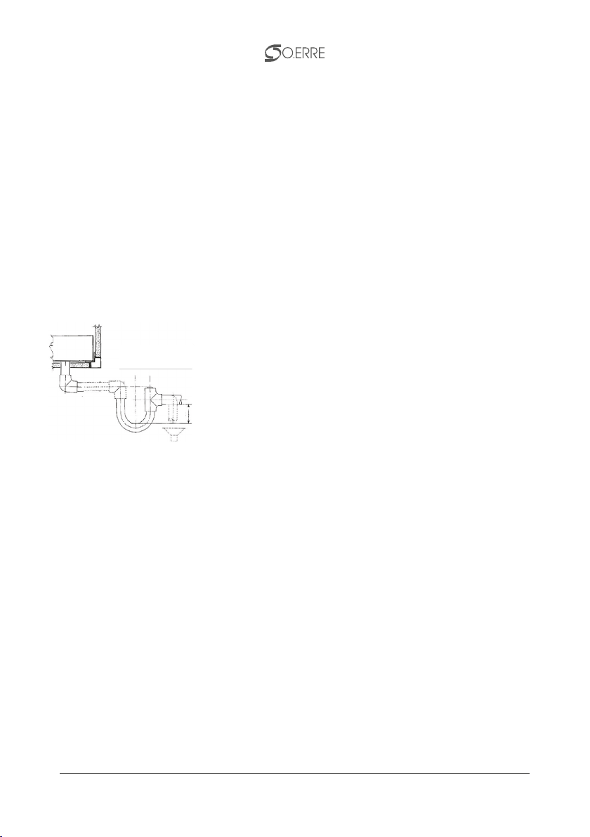
MANUTENZIONE VASCHE/BACINELLE RACCOLTA CONDENSA
TOGLIERE TENSIONE ALL’UNITA’ PRIMA DI ACCEDERE ALL’INTERNO
Nella vasca di raccolta della condensa può accumularsi sporcizia quindi si consiglia di pulire la va-
sca regolarmente e verificare l’intasamento della tubazione di scarico. Per il lavaggio delle bacinelle
raccolta condensa utilizzare prodotti approvati dal Ministero della Sanità comunque non corrosivi.
SCAMBIATORE DI CALORE
ASPIRAPOLVERE

10
16. MANUTENZIONE E INTERVENTI
DATA CONTROLLO ANOMALIA ESITO INTERVENTO FIRMA
Questo manuale rispecchia lo stato della tecnica al momento della sua pubblicazione e può essere modificato
senza preavviso.
La riproduzione, anche parziale, di questa pubblicazione e delle sue illustrazioni sono vietati. La O.Erre tutela i
propri diritti a termini di legge.

11
GENERAL INDEX
0. GENERAL INFORMATION pag 12
1. GENERAL SAFETY pag 13
2. LIFTING INSTRUCTIONS pag 13
3. INSTALLATION INSTRUCTION pag 13
4. INSTRUCTIONS FOR USE pag 15
5. SAFETY INSTRUCTIONS FOR MAINTENANCE pag 15
6. STORAGE pag 15
7. PROVISION pag 15
8. DISPOSAL pag 15
9. ELECTRICAL CONNECTIONS pag 16
10. AUTOMATIC BY-PASS CONNECTIONS pag 16
11. HYDRAULIC CONNECTIONS pag 17
12. AERAULIC CONNECTIONS pag 17
13. CHECK CURRENT CONSUMPTION pag 17
14. OPERATION AND USE pag 18
15. ROUTINE MAINTENANCE pag 18
16. MAINTENANCE AND OPERATIONS pag 19

12
0. GENERAL INFORMATION
The heat recovery units series TEMPERO ECO HV must be installed and operated in accordance
with the requirements contained in this manual.
The strict observance of these simple and basic instructions is a prerequisite for:
• Eliminate or reduce downtime due to faults or unforeseen anomalies;
• Increasing the life of the components and the entire unit;
• Decrease the costs of maintenance.
MACHINE DOES NOT SUITABLE FOR WORK ENVIRONMENT IN WITH EXPLOSIVE ATMOSPHERE
AND IN ENVIRONMENTS WITH HIGHLY CORROSIVE AGENTS.
TEMPERO
ECO HV 950 TEMPERO
ECO HV 2400 TEMPERO
ECO HV 3200
Nominal air flow (m3/h) 1000 2000 3500
Useful static pressure (Pa) 170 180 150
FANS (DATA FOR EACM FAN)
Installed power (W) 420 420 550
Poles (nr) 4 4 4
Round (RPM) 1350 1350 1350
Current (A) 4,6 4,6 6,8
Rated voltage (V) 230 230 230
Frequency (Hz) 50 50 50
Speeds (nr) 3 3 3
FILTER
Corrugated acrylic eciency G4 G4 G4
GENERAL TECHNICAL DATA TABLE
DATI ECODESIGN
Modello Eciency Nominal
air flow Useful static
pressure SFPInt SFPInt-2018 Front
speed Fan
eciency Internal
leakage External
leakage
% m3/h Pa W/m3/s W/m3/s m/s % % %
TEMPERO
ECO HV 950 81,6 1000 170 1430,3 1580,3 1,56 28,8 7,3 5,5
TEMPERO
ECO HV 2400 81,3 2000 180 1286,4 1355,3 1,59 33,9 5,9 4,1
TEMPERO
ECO HV 3200 80,6 3500 150 1200,5 1421,9 1,58 32,3 5,3 3,2

13
1. GENERAL SAFETY
The O.ERRE considers the safety and proper operation of the product only if the electrical system
and the power of the place of installation complies with current regulations and if the product is
installed and used according to the rules described below.
2. LIFTING INSTRUCTIONS
The load during both the charging and discharging , should always be lifted from the base of the
product by means of a crane or forklift with adequate capacity to support the weight , do not turn
it or place on the sides and submit to strong shock. The product is supplied with a suitable pro-
tective packaging that provides only shelter from dust and scratches the surface , it is advisable to
protect it from the elements. Take all precautions required by safety regulations to avoid possible
damage to persons or property.
3. INSTALLATION INSTRUCTIONS
The horizontal version can only be installed in the ceiling with support brackets or shelves and the
accessibility for periodic maintenance is permitted by the doors positioned downwards. Is neces-
sary to provide additional later space (space of respect). The ground positioning can be made only
with the vertical version that is provided with appropriate support legs and inspections are carried
out from the front. The installation of the machine, as well as the appropriate electrical connections
to ducts and fittings must be performed by skilled technicians in the industry. The machine also
requires a space environment free of obstacles and enabling the smooth opening of the doors of
inspection as well as enough space for the extraction of the filters and the electrical wiring of the
fans. The following is possible modes of fixing of the heat recovery unit . We emphasize that the
anchor points and the dimensioning of the brackets must be made from time to time in respect of
the plant situation and dimensioning of the static and dynamic system.

14
HORIZONTAL INSTALLATION
VERTICAL INSTALLATION
Plan view
R min
Side view
CONDENSATE PIPES
INSPECTION DOORS
Q min
NOTA: it is recommended to install the unit with the gradient of 1-2% in the exhaust direction of the condensate
to facilitate the evacuation of the latter.
R: TEMPERO ECO HV 950: 800mm
R: TEMPERO ECO HV 2400: 600mm
R: TEMPERO ECO HV 3200: 700mm
Q: TEMPERO ECO HV 950: 465mm
Q: TEMPERO ECO HV 2400: 490mm
Q: TEMPERO ECO HV 3200: 610mm
Front view
Upper view
CONDENSATE
PIPS KIT SUPPORT POINTS
INSPECTION DOORS
R min
Q min
R: TEMPERO ECO HV 950: 800mm
R: TEMPERO ECO HV 2400: 600mm
R: TEMPERO ECO HV 3200: 700mm
Q: TEMPERO ECO HV 950: 465mm
Q: TEMPERO ECO HV 2400: 490mm
Q: TEMPERO ECO HV 3200: 610mm
CAUTION: it is recommended to install the unit with the gradient of 1-2% in the exhaust direction of the
condensate to facilitate the evacuation of the latter.

15
4. INSTRUCTION FOR USE
Before operating the machine, make sure that the electrical connections are correctly wired and
the condensate drain is specially connected, check to make sure no foreign objects have been left
inside the machine and that any electrical cords are fixed adequately. Do not open the inspection
doors with moving parts or introduce hands with the machine running , as indicated by appropriate
pictograms.
5. SAFETY INSTRUCTIONS FOR MAINTENANCE
Before performing any maintenance make sure that the machine is disconnected from the power
supply. The prod- uct is made in order to facilitate maintenance operations that allow it to be carri-
ed out by qualified personnel. Where were carried out repairs or extraordinary maintenance, please
contact O.ERRE that will have them done by authorized personnel or give consent to be able to be
performed by other qualified personnel. For any other problem, doubt or anomaly before proce-
eding with operations that can be harmful to the machine or incorrect, contact the service oce
O.ERRE which will provide all the necessary information to be able to solve, if possible, the case.
6. STORAGE
Permitted storage of the machine for a long time as long as the place is dry, protected from the sun
and at a temperature between 0 and 40 ° C, protected from rain and humidity, maybe suggest to
keep the packaging intact and support the machine on pallets or shelves.
7. PROVISIONS
You cannot set aside the machine.
8. DISPOSAL
Do not attempt to disassemble the system yourself: disassembly of the product and any other
part must be carried out by a qualified installer in accordance with the relevant local and national
regulations in force.
The unit must be treated in a facility that specializes in the reuse, recyling and recovery of materials.
During disposal the components must be separated, recovered and disposed of in the appropriate
specialized centers according to the construction material:
• galvanized and / or prepainted steel sheets
• polyurethane foam
• expanded polypropylene
• mineral wool
• electrical and / or electronic equipment.
All necessary precautions must be taken to prevent damage to people and property and pollution
of the surrounding environment. For more information contact the installer or local authorities.
WEEE DIRECTIVE (ONLY FOR EU)
The WEEE directive (waste electrical and electronic equipment) defines the disposal and recycling
of electrical and electronic equipment. It provides that such waste is treated by special centers,
separate from those dedicated to the disposal of mixed urban waste. The user has the obligation
to dispose these products in centers adequately equipped and authorized to manage this type of
waste.

16
IMPORTANT: CONNECT EACH FAN TO 1 RG HV SPEED REGULATOR
10. AUTOMATIC BY-PASS
Automatic by-pass system consists of motorized damper drived by means of thermostats calibra-
ted at 18 ° C (opening) and 23 ° C (closed).
9. ELECTRICAL CONNECTIONS
The identification plate indicates the type of power supply, the motor current installed and the
maximum current consumption of the fans. The fans of this series are standard single-phase,
three-speed. The electrical connections must be performed by qualified personnel in compliance
with current regulations.
FOR ANY FAN PROVIDED THE SPECIAL ELECTRICAL WIRING. CLARIFICATION OR FOR ANY
DOUBT FOR ELECTRICAL CONNECTION, BEFORE THE WRONG WAY, OR CONTACT THE INSTAL-
LER OR DIRECTLY O.ERRE. O.ERRE NOT BE DETERMINED DIRECTLY RESPONSIBLE IF THE WI-
RING WILL BE DONE INCORRECTLY CAUSING DAMAGE OR MALFUNCTION OF THE MACHINE.
CONNECTION DIAGRAM BELOW.

17
11. HYDRAULIC CONNECTIONS
The unit is equipped with a drain for draining the fallen water into the condensate collection
basin formed during normal operation. The unit must be installed with a gradient of 1-2% in the
direction of the condensate discharge to facilitate evacuation of the latter. Always provide for
the drain pipe with a siphon with a minimum slope of 2% in order to avoid condensation water
stalls. The presence of the siphon is essential for the proper functioning of the machine in order
to avoid air suction and allow the natural outflow of condensation water. The condensate drain
must be con- nected to a rainwater drainage network. Do not use discharges of white or black
water to avoid possible aspirations of odors if the water contained in the siphon evaporates. At
the end of the work, check the regular flow of the condensate by pouring water into the basin.
The condensate drainage system must be carried out in a workmanlike manner and the periodic
check must be ensured (AT LEAST EVERY 6 MONTHS).
S2 (mm) = Ht (mm w.c.) x 0.75
Ht: FAN PRESSURE
12. AERAULIC CONNECTIONS
The duct connections should be made through circular ducts with the same diameters as those
provided on the machine. The technical sizing of the ducts will still be carried out as function of the
plant and of the pressure of the heat recovery unit. The machine is not equipped with anti-vibration
joints internal joints on the attack so we recommend preparing these ducts in order to avoid any
vibration.
13. VERIFICATION OF CURRENT CONSUMPTION
At full speed , check that the current consumption complies with the limits of the plate expressed in
the case of abnormal consumption turn o the fan and contact our support department.
WARNINGS:
• ALL WIRING AND ELECTRICAL COMPONENTS USED FOR THE INSTALLATION MUST COM-
PLY WITH THE REGULATIONS IN FORCE;
• THE POWER LINE MUST BE MADE IN ACCORDANCE WITH THE REGULATIONS IN FORCE;
• WIRING MUST BE DONE BY QUALIFIED TECHNICIANS ELECTRICIANS;
• THE CURRENT CONSUMPTION MUST COMPLY AS SET OUT IN THE DATA PLATE

18
14. OPERATION AND USE
Before operating the machine, make sure that the discharges are free, that the air duct systems is
free and, if present, appropriately dampers tuned.
15. ROUTINE MAINTENANCE
To enable smooth and steady performance of the machine and then a longer period of time it is
advisable to carry out some simple routine maintenance. The frequency of interventions depends
on the place and the quality of the air that is treated by the machine.
DISCONNECT THE POWER SUPPLY BEFORE ACCESSING ANY INSPECTION INSIDE THE MACHINE.
FANS: Check every 500 hours (approximately) of the cleaning operation of the fans and the pre-
sence of foreign bodies.
FILTERS: Check every 20 days (approximately) the quality of the filter media removing the fil-
ter from their guides. Being regenerable filters (depending on the state of filter cleaning), if the
conditions allow it is possible to clean the dust from the filter with a simple jet of air blown in the
opposite direction to the air flow or otherwise be necessary to proceed with the replacement of
the filter exhausted with other new ones with the same dimensions.
Also recommend the periodic inspection and cleaning of the heat exchanger always with an air jet
to remove any impurities or deposited with the help of bactericidal products approved by health
authorities.
REMOVE VOLTAGE TO THE UNIT BEFORE ACCESSING INSIDE
The cleaning of the filters is essential to maintain a high standard of air quality in the rooms tre-
ated and a proper internal cleaning of the internal components of the unit. Check every 20 days
(approximately) the quality of the filtering septum, extracting it from its guides the filter itself by
accessing the unit inspection doors. Since these are filters that can be regenerated (depending on
the state of cleanliness of the filter), if the conditions permit it is possible to clean regenerate the
dust filter with a simple blown air jet in the opposite direction of the flow or else it will be necessary
to replace the exhausted filter with new ones with the same dimensions.
EXCHANGER MAINTENANCE
REMOVE VOLTAGE TO THE UNIT BEFORE ACCESSING INSIDE
The recovery of the recuperator is essential to maintain the high heat exchange in accordance with
the technical dimensioning of the components. Cleaning can be carried out with a compressed air
jet (max 1.5 bar) in the opposite direction to the air flow from a distance of 10-15cm and / or with
a vacuum cleaner.
Be careful not to damage the exchange fins: use professionalism during the cleaning phase.
To perform the cleaning it is necessary to remove the panel corresponding to the by-pass module,
remove the by-pass and access with the cleaning tools. After cleaning, reassemble what has been
removed in the reverse sequence.
MAINTENANCE OF TANKS / CONDENSATE COLLECTION BASINS
REMOVE VOLTAGE TO THE UNIT BEFORE ACCESSING INSIDE
Dirt can accumulate in the condensate collection tank, so it is advisable to clean the tank regularly
and check for clog- ging of the drain pipe. To wash condensation basins, use non-corrosive pro-
ducts approved by the Ministry of Health.
HEAT EXCHANGER
VACUUM CLEANER

19
16. MAINTENANCE AND OPERATIONS
DATE CHECK OR FAILURE RESULT ACTION SIGNATURE
This manual reflects the state of the art at the time of publication and may be changed without notice.
The reproduction, even partial, of this publication and its illustrations is prohibited.
The O.ERRE protection of their rights under the law.

EP S.p.A Via Del Commercio 1, 25029 - Travagliato BS (Italy)
ph. +39 030 68 62 341 / fax +39 030 68 62 051
COD. P06151001
This manual suits for next models
2
Table of contents
Languages:
Other O.ERRE Fan manuals
Popular Fan manuals by other brands

Hinkley
Hinkley HOVER FLUSH 60 instruction manual

Envirovent
Envirovent IPX4 installation guide

Salda
Salda RIS 2500HW EC Technical manual

Siemens
Siemens 3RW49 66 operating instructions

Ruck Ventilatoren
Ruck Ventilatoren DHA EC CP 20 Series Installation, Operating and Maintenance Instruction

Delta Electronics
Delta Electronics FFB0412EHN Dimensions and installation information