O.S. engine OGA-100 KIT User manual

2021.08.01
O.S. ENGINES MFG. CO., LTD.
100W Generator for UAV
OGA-100 KIT
for GF40U-FI
INSTRUCTION MANUAL
version 2.41E

【OGA-100A】
【ORF-200】
6-15 3-Chome Imagawa Higashisumiyoshi-ku
Osaka 546-0003, Japan
TEL.+81-6-6702-0225
FAX.+81-6-6704-2722
http://www.os-engines.co.jp
ABOUT THE PRODUCT
1
・OGA-100 in the kit also has a stay, which supports rear part of the generator. It is an extra part included
in the kit to mount on GF40U-FI.
・This is OGA-100 generator kit to be mounted on GF40U-FI. The kit contains OGA-100 generator with a
mount, a drive belt, a drive pulley, ORF-200 regulate rectifier.
・OGA-100 is a 3-phase AC generator suitable for small engines.
・It applies a brushless motor to the system and generates electricity with stability.
・It is equipped with UH grade Neodymium magnets that have powerful magnetic force with high heat
resistance (180 ℃).
・ORF-200 is an open type regulate rectifier; an effective DC-DC converter type.
・Output voltage is adjustable from DC6V through DC28V. (The factory setting is DC12V)
・Maximum output: 200W (DC12V)/10 minutes. (when atmospheric temperature is 20℃.)
・Maximum current: 16A (DC12V). (when atmospheric temperature is 20℃.)
・Maximum input voltage: 100V (AC).
*The specifications are subject to alteration for improvement without notice.
*Consult us for any questions on this product and return for repair.
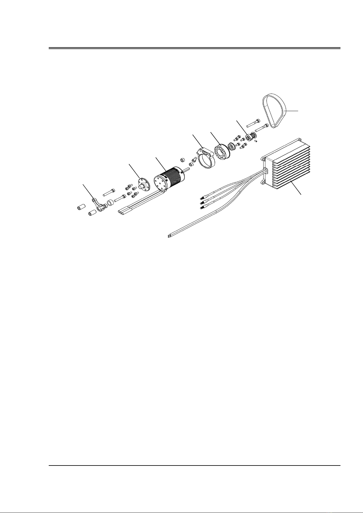
OGA-100A Generator
ORF-200 Regulate rectifier
Belt
Driven pulley
Generator adaptor(F)
Generator support(F)
Generator adaptor(R)
Generator support(R)
2
NAMES OF THE PARTS
1.
2.
3.
4.
5.
6.
7.
8.
1
2
3
4
5
6
7
8
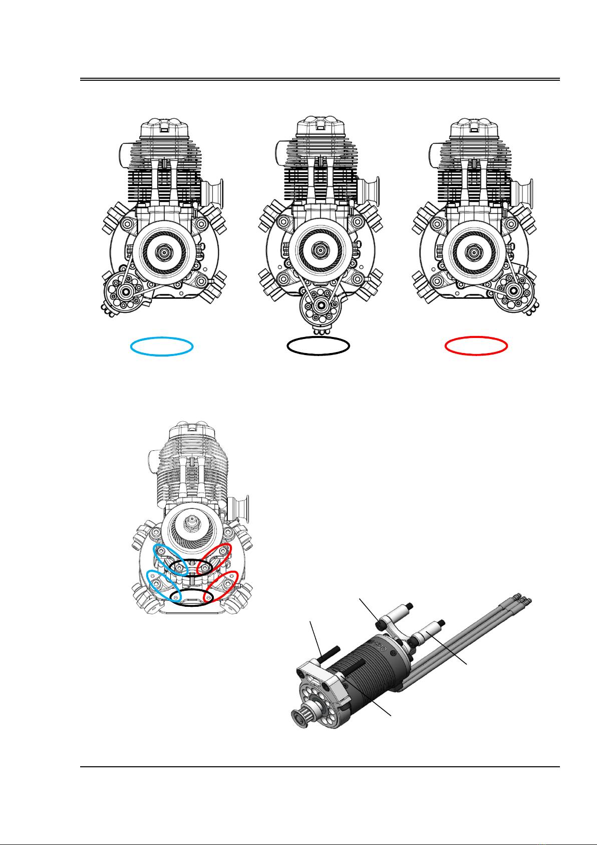
・
Mount the Generator after mounting the engine.
3
・The position of the generator (OGA-100A) is choosable from the three positions shown above.
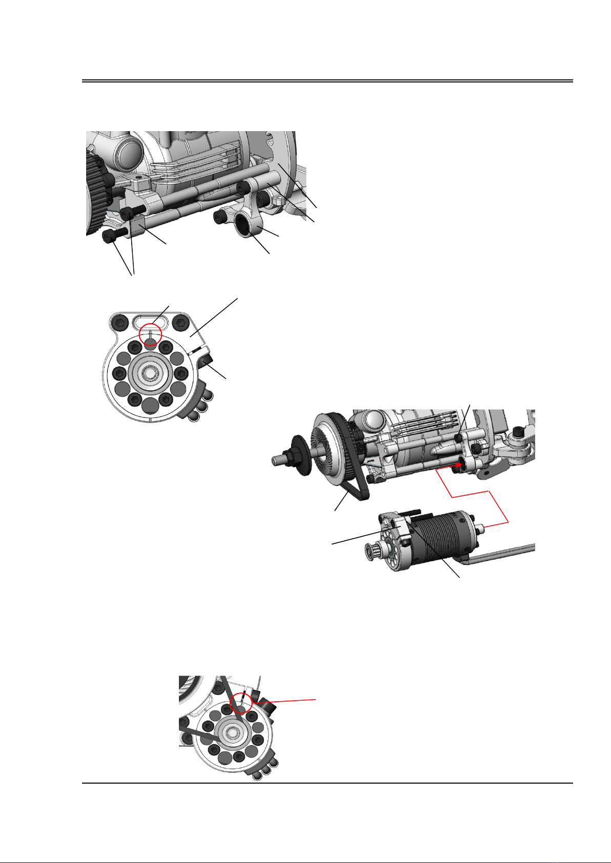
Installation
Right side left side
Lower
M4x30 Bolt
M4x25 Bolt
4.5mm Spacer
15mm Spacer
Use four screw holes for each depending
on the mounting position.
OGA-100A GENERATOR
【
Example when mounting on the left side
】
【
reference
】
4. Loop the belt over the Drive pulley
and the engine pulley.
5. Insert the Generator into Urethane
bushing of the Generator support (R).
6. Attach the Generator support (F)
to the Generator mount together
with 4.5mm Spacers using M4x30
Bolt.
7. Fasten the M4x25 bolts of the Generator support (R) that you temporarily fastened earlier. Loosen
the Lock bolt of Generator support (F) and check if belt tension is adjustable by rotating the generator
body.
8. Rotate the generator body clockwise (viewing from the front of the engine) and adust the belt tension.
Press on the middle point of the belt with a finger and set deflection to around 2mm. Tighten the Lock
bolt after adjusting the belt tension.
The alignment mark is roughly here when the belt is
new.
4
Installation
1.Remove the pair of front bolts (M4 x 15) on the generator mount, where you intend to fit the
Generator. There bolts are unnecessary in case the Generator is fit.
2. Bolt the Generator support (R) to Mounting plate(F)
together with 15mm Spacers using M4x25 Bolts. Fasten
only temporarily. The Generator support (R) piece has
two sides. Check this closely.
3. Loosen the Lock bolt on the Generator support(F) and align the
marks as shown above in the red circle. Tension of the belt is the
loosest at this position.
Generator mount
1. (Please remove it.)
Urethane bushing
2. Generator support(R)
Mounting plate(F)
15mm Spacer
5.
7.
4.5mm Spacer
4.
6.Generator
support(F)
Lock bolt
3. Generator support(F)

③ Attach the lid with the four screws (tightening torque 0.5N-m). Do not attach the lid reverse since the
lid is asymmetric with a cutout for cables.
Adjustment method of output voltage
・Output voltage is adjustable between 6V to 28V.
《How to reset the output voltage》
① Remove the four screws on bottom of ORF-200, and take out the lid.
② Reset the voltage by turning the trimmer shown in the picture. You can increase the voltage by turning
it clockwise. Adjust the output voltage with no load without connecting output cable to any equipment
inputting double or more voltage than the output voltage you set. The input voltage does not have to be
3-phase AC when you adjust the output voltage. You can use single-phase AC or even DC. Use two of the
three input cables randomly selected when you use single-phase AC or DC for input.
Installation
5
CAUTION:
・Do not exceed the rated output values. The regulate rectifier can be overheated under high
atmospheric temperature even it is used within the rated values. So position it in a well-ventilated
place.
・When output of ORF-200 is connected to your equipment, put a 15A – 20A fuse in the RED cable
(DC +).
Installation
・Provide enough anti-vibration measures to mount it in an aircraft.
・Determine the position of the regulate rectifier, well ventilated, not to be exposed to radiation heat and
engine exhaust gas.
・Use four M4 screws when it is mounted.
・Connect three white input cables of ORF-200 to three output cables of the generator. There is no
polarity on each three cables.
・Output cables (RED DC +, BLACK DC -) do not have connectors. Prepare connectors that fit to your
equipment by yourself.
ORF-200 REGULATE RECTIFIER
1
Voltage adjusting volume
Turn clockwise to increase
the voltage

■
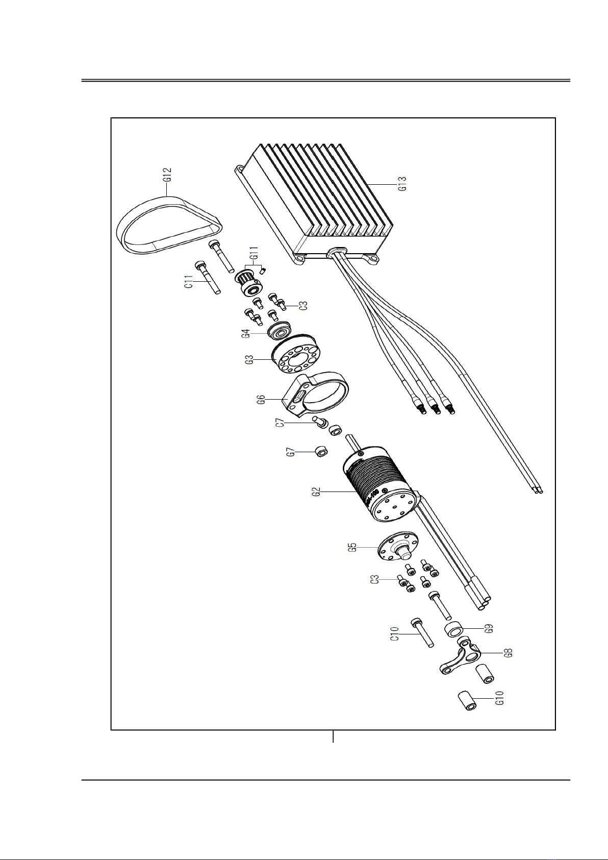
PARTS LIST / OGA-100 KIT for GF40U-FI
Parts list
54059002
4AD50013
Description
OGA-100 KIT FOR GF40U-FI
OGA-100A GENERATOR
GENERATOR ADAPTOR (F)
C7
C10
C11
G11
G12
4AD50016
54059006
4AD50017
G8
G9
6
G13
C3
G10
Code No.
54062000
51040120
54059001
4A632000
4AD50012
BELT
URETHANE BUSH
GENERATOR SPACER 15 (2PCS)
GENERATOR SUPPORT 100W (R) GF40U
No.
G1
G2
G3
G4
G5
BEARING
GENERATOR ADAPTER (R) OGA-100A
GENERATOR SUPPORT 100W (F) GF40U
GENERATOR SPACER 4.5 (2pcs.)
G6
G7
54062003
54062005
79871425
79871430
CAP SCREW SET M4.0X30 (10pcs./set)
DRIVEN PULLEY (12T) OGA-100
54055000
79871109
79871410
REGULATE RECTIFIER ORF-200
CAP SCREW SET M3.0X6 (10pcs./set)
CAP SCREW SET M4.0X10 (10pcs./set)
CAP SCREW SET M4.0X25 (10pcs./set)
Parts list
OGA-100 KIT for GF-40U-FI
G1
7

■
SPECIFICATION (OGA-100A)
Weit:
205 g
Lead wire length:
100 mm
Female connector:
φ3.5 mm
Induced voltage Ke:
1.053 mV/rpm
Rated voltage:
12V @11400rpm
Rated current:
7A
Maximum current:
15A
Maximum output
:
100W(12V)/30minutes (the value in atmospheric temperature 20
℃
)
60W/continuous (the value in atmospheric temperature 20
℃
)
Poles:
4
Number of phases:
3
Phase resistance:
60mΩ
International protection:
Equivalent to IP62
■
SPECIFICATION (ORF-200)
Weit:
395 g
Input lead wire length:
300 mm
Male connector:
φ3.5 mm
Output lead wire length:
300 mm
Number of phases:
3
Rated voltage:
60 V (AC)
Maximum input voltage
100 V (AC)
Rated output voltage:
12 V
Maximum output voltage
28 V
Rated output current:
12 A
Maximum output current:
16 A
Rated output
:
140W (12V) (the value in atmospheric temperature 20
℃
)
Maximum output:
200W (12V)/10 minutes (the value in atmospheric temperature 20
℃
)
International protection:
Equivalent to IP63
Installation
8
・
Output voltage/wattage/current: 6-28V adjustable, Max 200W, Max 16A.
Do not exceed 200W/16A when you set the voltage.
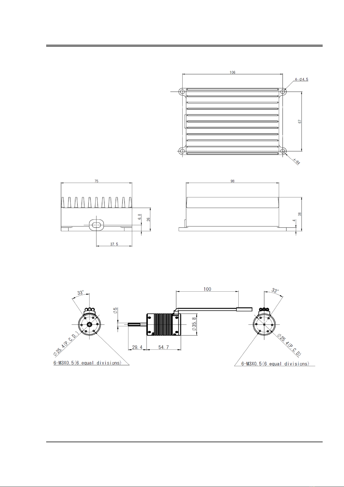
Demantions
9
note 1. Use the mounting screws whose length does not exceed the thickness of your bracket +
4mm, so that the length of screws which is screwed into the generator body is less than 4mm. If
you screw into the screw body longer than 4mm, the screw will contacts the motor coil and will
cause short circuit.
Unit : mm
ORF-200
Unit : mm
(note 1.) (note 1.)
OGA-100A

MEMO
10
Table of contents
Popular Portable Generator manuals by other brands


Peak Scientific
Peak Scientific Solaris XE user manual

Nature's Generator
Nature's Generator Nature's Power Pod user manual

Husqvarna
Husqvarna 1365GN Operator's manual

Briggs & Stratton
Briggs & Stratton PowerBoss 30221 Illustrated parts list

Briggs & Stratton
Briggs & Stratton BSP5500L owner's manual

Titan
Titan TG 6500 owner's manual


