Altrad Belle GPX Range User manual

1
870/50000/0
06/17
Operators Manual
GB
BELLE
4
GPXRANGE

5
Machine Description
GB
1. Choke lever.
2. Fuel ON / OFF lever.
3. Engine ON / OFF switch.
4. Air Filter Housing.
5. Fuel Tank.
6. Exhaust.
7. Lifting Point.
8. Socket.
9. Alternator.
10. Voltage Switch
11. Circuit Breaker.
12. Earth
13. Securing Pin (for use when stacking machines)
(Diagram based on the GPX 3400 Generator)
On
On
On
Off
12
9
8
13 11
10
11
8
1
2
3
4
5
7
6
Switch Box Front View
Switch Box Rear View

6
Technical Data
GB
Model GPX 2700 GPX 3400 GPX 5000
A - Overall Length (mm) 618 618 728
B - Overall Width (mm) 432 432 512
C - Overall Height (mm) 515 515 595
Weight (Kg) 46 47 64
Rating @0.8 p/f (kVA) 2.7 3.4 5.0
PRP Rating (kW) 2.2 2.7 4.0
COP Rating (kW) 2.0 2.5 3.6
Engine Power @3000rpm (kW / Hp) 4.3 / 3.3 4.3 / 3.3 6.2 / 4.6
Alternator NSM K100 Range
Frequency (Hz) 50 50 50
Phase 111
Maximum Current @ 110v 20.00 24.5 36.4
Maximum Current @ 230V 9.57 11.7 17.4
Fuel Tank Capacity (Ltr) 3.1 3.1 5.6
Running hours at @ 90% of COP (Hrs) 2.5 2.3 2.8
No. of 110v 16 amp sockets 112
No. of 230v 16 amp sockets 111
No. of 110v 32 amp sockets -11
Sound Power Level LWA 95 95 96
The above have a 2 pole 3000 r/min 50Hz 115/230V dual voltage alternator.
All our generator ratings are based on a fully run in engine.
Environment
Safe Disposal.
Instructions for the protection of the environment. The
machine contains valuable materials. Take the discarded
apparatus and accessories to the relevant recycling
facilities.
GB
Component Material
Main Frame Steel
Chassis Steel
Engine Aluminium
Flexible Mounts Steel and Rubber
Various Parts Steel and Aluminium
B A
C

7
Decals
GB
C
A
F
A
E
AA
D
D
B
A - Branding Decals
Decals to identify the make and model of the machine.
B - Voltage Switch Indicator Decal
Decal to identify what voltage is selected.
C - Rating Decal
Decal to includes main Technica Data, including Noise Level.
D - Lifting Point Decal
Identi¿es the Lifting Point.
E - Earth Decal
Identi¿es the postition of the Earth point.
F - Safety Decal
General safety instructions for operating the machine.
Please Read
Operators Manual Wear Protective
Footwear Wear Ear
Protection Wear Eye
Protection
Switch Box Front View
Switch Box Rear View

8
General Safety
For your own personal protection and for the safety of those around you, please read and ensure you fully understand the following
safety information. It is the responsibility of the operator to ensure that he/she fully understands how to operate this equipment safely.
If you are unsure about the safe and correct use of the Generator, consult your supervisor or Altrad Belle.
BEFORE STARTING THE GENERATOR
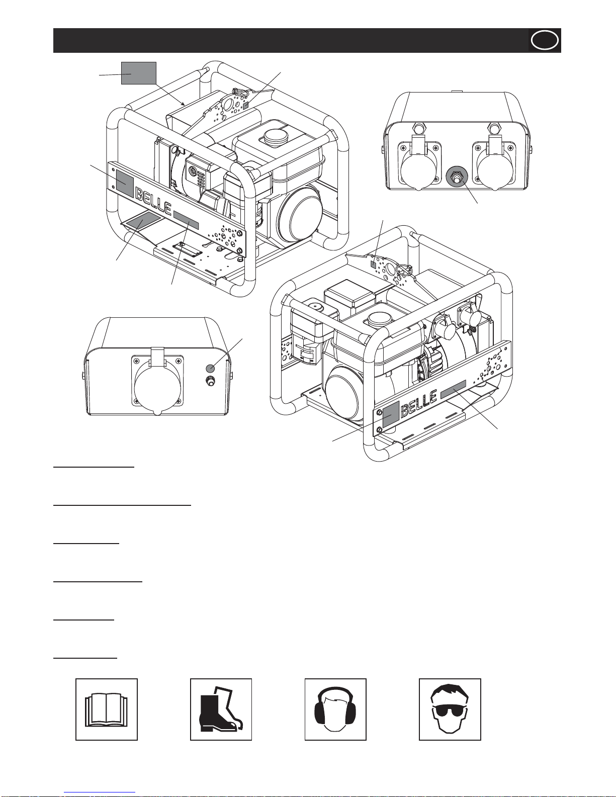
• Suitable clothing as follows should meet relevant EEC/local standards: overalls, work boots and ear defenders.
• Become familiar with the controls before operating the machine.
• Place the generator on ¿rm/level ground.
• Place the generator at least 1 metre away from buildings and other equipment during operation.
• The generator should be sheltered from the rain and water.
• Refuel in a well ventilated area with the engine switched off. Check for spilled fuel or leaks.
• Ensure all covers are ¿tted.
• Ensure that extension cables are carefully laid out avoiding liquids, sharp edges and places where vehicles might run over. Unroll
it fully or it could catch ¿re.
• Replace any worn/damaged decals.
• Remove all packaging material before operating.
WHEN OPERATING THE GENERATOR
• Keep children and pets away from the generator.
• DO NOT run the generator in an enclosed area.
• Exhaust gases contain poisonous carbon monoxide.
• Adequate ventilation must be provided, to avoid serious overheating and subsequent damage to the windings.
• DO NOT operate the generator with wet hands, it is a potential source of electric shock.
• DO NOT operate the generator without correct instructions.
• DO NOT attempt to operate the generator in the snow and rain and do not let it get wet.
• DO NOT directly connect the generator to the domestic power sockets.
• BEWARE of hot surfaces.
• Before refuelling, switch off the engine and allow it to cool.
• When refuelling, DO NOT smoke or allow naked Àames in the area.
• Spilt fuel must be made safe immediately, using sand. If fuel is spilt on your clothes, change them.
• Store fuel in an approved, purpose made container away from heat and ignition sources.
SAFETY AND ACCIDENT PROTECTION
Operating Instructions:
All persons who apply, assemble, operate, start, control, maintain or repair this machine must read and understand these operating
instructions.
Owner Responsibility:
The owner must ensure that only quali¿ed persons operate, maintain, or repair this machine.
Storage:
When not in use, store in a dry, locked place. Keep away from children.
Operation for the Intended Purpose:
This generator is designed to generate electricity up to its stated maximum amperage loading, at the voltage stated on the appliance
rating plate. Do not attempt to use it to do anything else. Do not use it in an explosive atmosphere.
Transport :
Refer to the engine and alternator manuals provided for full transport recommendations.
GB
Improper maintenance or use can be hazardous. Read and Understand this section before you
perform any maintenance, service or repairs.
CAUTION
Fuel is Àammable. It may cause injury and property damage. Shut down the engine, extinguish all
open Àames and do not smoke while ¿lling the fuel tank. Always wipe up any spilled fuel.
CAUTION

9
PRE-OPERATION
• Check your generator before use and IMMEDIATELY replace any damaged parts.
• Place the generator on ¿rm level ground with the engine switched OFF.
• Check the engine oil level, low oil levels will result in the engine not starting.
• Check the fuel level.
• Check the electrical installation according to the usage.
• Check the earth cable. Replace IMMEDIATELY if damaged.
• This equipment is likely to emit a Sound Power Level (LWA) of up to 96dB(A). Wear appropriate ear defenders.
• Your Altrad Belle generator comes preset and NO adjustment is necessary.
• Be aware of how to stop the generator by use of the ignition switch.
Refer to the engine and alternator manuals provided for full pre-operation check.
STOPPING
• Switch OFF the loads.
• Switch OFF the engine.
• Turn the fuel tap to the CLOSED position.
STARTING - HONDA GX200 / GX270
• Switch OFF all electrical appliances connected to the generator.
• Remove all objects placed on, or within one metre of the generator.
• Open the fuel tap by moving the fuel ON / OFF lever fully to the right.
• If starting the engine from cold, set the choke ON by moving the choke lever
fully to the left. If restarting a warm engine, the choke is usually not required,
however, if the engine has cooled to a degree, partial choke may be required.
• Turn the engine ON / OFF switch clockwise to the ‘I’ position.
• Set the throttle to the idle position by moving the throttle lever fully to the right.
• Taking a ¿rm hold of the control handle with one hand, grasp the recoil starter
handle with the other. Pull the recoil starter until engine resistance is felt, then let
starter return.
• Taking care not to pull the starter’s rope fully out, pull the starter handle briskly.
• Repeat until the engine ¿res.
• Once the engine ¿res gradually set the choke lever to the OFF position by moving
it to the right.
• If the engine fails to ¿re after several attempts, follow the Troubleshooting Guide.
• To stop the engine, set the throttle to idle and turn the engine ON / OFF switch anticlockwise to the ‘0’ position.
• Turn the fuel OFF.
• Select required voltage.
Your Altrad Belle generator is now ready for operation.
TREAT THE ELECTRICITY PRODUCED BY THIS GENERATOR AS YOU WOULD MAINS ELECTRICITY.
Operating Instructions
GB
The engine running speed is pre-set by the manufacturer and must not be adjusted.
CAUTION
The engine speed governs the frequency of the electric supplied (50Hz in U.K.). If the speed is inadvertently disturbed the generator
must immediately be stopped and not used until reset.
Damage to electrical appliances can occur if they are supplied with the wrong electrical frequency.
Before you operate or carry out any maintenance on this machine YOU MUST READ and STUDY
this manual.
WARNING
Throttle Lever
Choke Lever
Fuel ON/OFF
Lever.

10
The engine is ¿tted with an oil alert switch that will automatically stop the engine if there is a fault in the oil system.
Circuit Breaker
In case of accidental overload the generator is protected by circuit breakers, thus protecting the generator windings by limiting the
current drawn at the preset level. This type of circuit breaker offers improved protection to the generator and any appliance being
used.
However this type of breaker offers no earth leakage protection but will trip-in in case of a dead short that produces a current 25%
above the circuit breaker rating. The breaker has a delay action that allows current surges, often required when starting electrical
motors. The delay of the circuit breaker is designed so that if the current required is too great eg. too large a motor, the supply will cut
off.
Be careful to ensure that appliances do not exceed 15% of the generators rated load capacity for more than 10 minutes in the hour.
A substantial overload will switch off the circuit breaker. Marginal overload will not switch off the circuit breaker but will shorten the
generators service life.
Be sure that all electrical appliances are safe before connecting to the generator. If an appliance fails or stops, switch off the load and
engine. Examine the appliance for signs of malfunction.
Operating Instructions
GB
OPERATION
Electrical outputs will vary according to the model. Refer to the rating plate for full details and see the following section on component
identi¿cation.
• 110v AC 16 amp use yellow socket.
• 230v AC 16 amp use blue socket.
• (110v AC 32 amp use yellow socket, 5 kVA & 6 kVA only).
All our 230/110v dual voltage generators have ‘Àoating’ windings and are not referenced to frame or
earth.
CAUTION
The third ‘earth’ socket pin of the BS4343 socket is connected to the frame. Ensure frame has
suf¿cient ground connection at all times.
CAUTION
It is recommended that all electrical connections, including earth, are checked and inspected at regular
intervals.
CAUTION
If installing a generator into a domestic mains supply for use as a secondary back up, this connection
must be done by a quali¿ed competent electrician to ensure correct earthing and installation to the IEE
Regulations for Electrical installations or your regional electrical regulations.
CAUTION

11
ESTIMATING POWER CONSUMPTION
Identifying the correct generator for an application is not always straight forward. There is often dif¿culty determining the actual
power requirements to both start and run the expected load(s). A generator should be considered capable if it can operate within
the frequency and voltage speci¿cation, for one second after it begins to power the appliance. Some appliances, especially electric
motors, may overheat or become damaged by prolonged or repeated connection to a power source, which is insuf¿cient to start them.
The two important factors to remember are:
1) Ensure the total load does not exceed the generators rated continuous output, for more than 30 minutes.
2) Never exceed the generator’s maximum output speci¿cation.
The best way to ensure that neither of the above occurs is to contact the manufacturer of the equipment that is intended for use with
the generator. Alternatively a useful way to measure the starting and running current for the appliance is to use a Altrad Belle Minigen
meter. The unit can monitor volts, amps and frequency to help guarantee the performance of both the generator and tools. If it is not
possible to test the appliance, then the following information will allow the size of the generator required to be estimated.
RESISTANCE TYPE LOADS
Examples: Light bulbs, toasters, hair dryers, coffee pots, irons and other appliances, which have heating elements.
This type of load is usually rated in watts, but sometimes a combination of watts and amps will be given. It is possible to select a
suitable generator by comparing the speci¿cation of the generator with the generator output speci¿cation.
Method 1: Use when load is rated in watts.
Estimating Power Consumption
GB
Indicated wattage of resistance type load = Watt = VA = Required Generator Output
Power factor for resistance 1
Method 2: Use when voltage and measured current are known.
INDUCTIVE AND CAPACITIVE TYPE LOADS:
Examples: Appliances or tools with electric motors, air conditioners, microwave ovens, televisions, Àuorescent lights and any other
appliances that are not simply resistance type loads.
This type of appliance (especially those that use electric motors) may require more power to start then is indicated by their running
power ratings. It is not possible to select a generator by the power rating information given on the appliance; it is necessary to
know both the staring current and running current required.
Running power requirements:
Method 1: Use when load is rated in watts.
Speci¿ed voltage of the x Measure current of the = VA = Required Generator Output
resistance type load resistance type load
Indicated wattage of inductive/capacitive load = Watt = VA = Required Generator Output
Indicated Power factor <1
Method 2: Use when voltage and measured current are known.
Speci¿ed voltage of the x Measure current of the = VA = Required Generator Output
inductive/capacitive load inductive/capacitive type load
Starting power requirements:
Method 1: Use when starting current and voltage are speci¿ed.
Indicated starting current x Speci¿ed voltage of the = VA = Starting power requirements
inductive/capacitive load
Method 2: Use when starting current and voltage are speci¿ed.
Measured starting current x Speci¿ed voltage of the = VA = Starting power requirements
inductive/capacitive load

12
Estimating Power Consumption
GB
GENERAL GUIDELINES
Refrigerators, freezers, compressors and central heating pumps usually have induction type motors and the starting current can be
three times higher than the running current.
Fluorescent lamps require approx 1.5 times their stated wattage to start-up.
Microwave ovens are often referred to by their cooking power, which is often half the operating power. Starting up the oven consumes
an extra 25%, which is used to energise the capacitor. This means that a microwave rated at 600 Watts (cooking power) actually
needs 1500 watts to operate it.
It is essential to consult the manufacturer when considering using electric welders.
Examples
a) Kettle (Speci¿cation: 230V 50Hz, 2200W, unknown Amps) - Resistance load
Indicated wattage of resistance type load = 2200 = 2200 VA or 2.2kVAto operator
Power factor for resistance 1
Speci¿ed voltage of the x Measured current of the = 110 x 5.5 = 605 VA or 0.605 kVAto operate
inductive/capacitive load inductive/capacitive load
b) Mini 150 concrete mixer (Speci¿cation: 110V 50Hz, 600W, 5.5A) - Inductive / Capacitive load
The power required to start the mixer is actually 3 x this amount, therefore: 3 x 0.605kVA = 1.815 kVA to start the machine.

13
Servicing
GB
Before starting any maintenance or repairs, stop engine or switch off motor, and isolate from the main power supply. On completion of
maintenance, check that the generator functions correctly and that all guards are correctly ¿tted.
EXTENSION CABLES
If you need to use an extension cable it must be no longer than 30 metres (100 feet) in length. Ensure that the extension cable is
carefully laid out avoiding liquids, sharp edges and places where vehicles might run over it or become trapped. Unroll it fully or it will
overheat and could catch ¿re. Make sure that any extension cable connections are dry and safe.
COMBUSTION ENGINES
Be aware of exhaust venting directions.
CAUTION
The engine needs a regular oil check.Try not to run low on fuel as this may result in sediment from the bottom of the tank doing
damage to the injector and pump. Repairs and recti¿cation of pipework and components affected by contaminants in fuel
cannot be accepted as warranty, neither will faults caused or contributed to by the machine running out of fuel. You may
need to bleed the fuel system free of air before starting. For initial engine ¿ll or top up use a suitable engine oil of a 10W/30 grade. In
your own interests read the makers instruction leaÀet issued with the machine before starting up.
LUBRICATION AND RUNNING
See Maintenance Schedule Section and Operating Instructions.
Maintenance Schedule
GB
Only authorised dealers should repair the generator, and within the requirements of the CE mark (where applicable), where no
deviation from the original speci¿cation must take place.
Please refer to the Engine Manufacturers instruction leaÀet, before attempting any maintenance checks or procedures.
Routine Maintenance Each Use First Month /
20 Hours 3 Months
/ 50 Hours 6 Months /
100 Hours Yearly /
300 Hours
Engine Oil Check Level 9
9
Change
9 9
Air Cleaner Check
9
Clean
9
(1)
Sediment Cup Clean
9
Spark Plug Check - Clean
9
Valve Clearance Check - Adjust
9
(2)
Fuel Tank & Strainer Clean
9
(2)
Fuel Line Check (Replace if necessary) Every 2 Years (2)
(1): Service more frequently when in dusty areas.
(2): These items should be serviced by an authorised Honda dealer.
Any maintenance and repairs carried out, to any part of the electrical circuit, must be undertaken by a
quali¿ed electrician.
CAUTION
Disable engine starting circuits before carrying out any maintenance or repair.
CAUTION

14
Troubleshooting Guide
GB
Problem Cause Remedy
Engine will not start.
Fuel tap not turned on. Turn fuel on.
No fuel in tank. Fill fuel tank.
Oil not ¿lled to correct level. Fill oil to correct level.
Engine run switch not turned on. Set engine control correctly.
Choke not set correctly. Set engine control correctly.
Spark plug fouled. Replace / clean spark plug.
Air cleaner blocked. Replace / clean air ¿lter.
Engine still will not start. Major Fault Contact Agent or Altrad Belle.
Engine runs rough.
Air cleaner blocked. Replace / clean air ¿lter.
Spark plug fouled. Replace / clean spark plug.
Choke set incorrectly. Set engine control correctly.
Dirty / stale fuel. Drain and replace fuel.
No electrical output. Voltage selector switch incorrectly
positioned. Select the correct voltage.
Circuit breaker tripped. Re-set circuit breaker.
Fault Finding for Alternators
GB
FAULT
OFF Load
No Voltage
Output Incorrect
Voltage Voltage
Unstable
Check
Residual Voltage Check
Speed Check Engine
Governing
Check all
Stator Resistances
Check
Capacitor
Check Rotor
Resistance
Check Rotating
Diodes
ON Load
Over-
heating
Over Load
Inlet or Outlet
Opening
Obstructed
Hot Engine
or Generator
Air Circulating
Voltage
Unstable
Check
Engine
Governing
Check
Connections
Incorrect
Voltage
Check
Speed
No Output
Voltage
Check Load
for Short
Circuit

15
Circuit Breaker Speci¿cations
GB
kVA 110v 230v
2.7 20 9
3.4 25 12
5.0 35 20
Capacitor Chart
GB
kVA Replacement Capacitor Required
2.7 14 ȝƒ
3.4 14 ȝƒ
5.0 30 ȝƒ
Application
GB
Before deciding which generator you need, it is important to consider ALL the appliances you will be operating, how many will be
used simultaneously and the TOTAL current consumption at any one time. Most appliances have a description plate stating the
current, usually in watts.
IMPORTANT
TV sets, cookers HI-Fi, kettles and ¿lament lamps have resistive loads, their starting and running current being virtually the same, and
as stated on the description plate. Fluorescent lamps (on average) require approximately 1.5 times their stated wattage to start-up.
Hand tools with universal-type motors need an extra 5% added to their stated power consumption.
Altrad Belle Mini/Maxi concrete mixers, refrigerators, vacuum cleaners, freezers and central heating pumps usually employ induction/
capacitor type motors. Their starting current can be three times the normal running requirement: check the description plate carefully.
Note for example, a Altrad Belle Mini 140 and 150 mixer, having a motor wattage of 650 watts input multiplied by three would give a
total starting requirement of 1950 watts, therefore a 2.2 kw Altrad Belle generator would be required.
If in doubt, check with the appliance manufacturer. Microwave ovens are often referred to by their cooking power,which on average is
half their actual operating power consumption. However, switching on the oven consumes an extra 25% power as the capacitor is
energised. Thus, a normal ‘600 watt’ microwave oven actually needs 1500 watts to operate it.
TYPICAL CURRENT CONSUMPTION
The following is presented as an approximate guide to the power requirements including start up when applicable.

16
Wiring Diagrams
GB
NLNL
2
GY
N
1
GY
R
33
NR
YU
W
4
321
456
17
Y
Y6
BUNR
5
BUNR
GPX 2700
GPX 3400
NL
2
GY
UN
N
3
W4YR
GY
3
RY
NL
1
GY
RY
5
Y
Y6
5
RUBN
RUBN
NL
7
R

17
Wiring Diagrams
GB
GPX 5000
KEY
N- Brown
U - Blue
G/Y - Green/Yellow
W- White
R- Red
Y- Yellow
B- Black
1- 115v Socket (16 amp)
2- 230v Socket (16 amp)
3- Circuit Breaker
4- Change Over Switch
5- Connector Block Alternator
6 - Alternator
7- 115v Socket (32amp)
17 - Capacitor
N- Neutral
L - Live
NL
2
GY
UN
N
3
W4YR
GY
3
RY
NL
1
GY
RY R
5
Y
Y6
5
RUBN
RUBN
NL
1
NL
7
GY
YR

18
Your new Altrad Belle Generator is warranted to the original purchaser for a period of one-year (12 months) from the original date of
purchase. The Altrad Belle warranty is against defects in design, materials and workmanship.
The following are not covered under the Altrad Belle warranty:
1. Damage caused by abuse, misuse, dropping or other similar damage caused by or as a result of failure to follow assembly,
operation or user maintenance instructions.
2. Alterations, additions or repairs carried out by persons other than Altrad Belle or their recognised agents.
3. Transportation or shipment costs to and from Altrad Belle or their recognised agents, for repair or assessment against a
warranty claim, on any machine.
4. Materials and/or labour costs to renew, repair or replace components due to fair wear and tear.
The following components are not covered by warranty.
• Drivebelt/s
• Engine air ¿lter
• Engine spark plug
Altrad Belle and/or their recognised agents, directors, employees or insurers will not be held liable for consequential or other
damages, losses or expenses in connection with or by reason of or the inability to use the machine for any purpose.
Warranty Claims
All warranty claims should ¿rstly be directed to Altrad Belle, either by telephone, by Fax, by Email, or in writing.
For warranty claims:
Write to:
Altrad Belle Warranty Department,
Sheen, Nr. Buxton,
Derbyshire,
SK17 0EU
England.
Warranty Registration:
In the bid for ALTRAD Belle to become greener and more eco friendly, we have now introduced online
Warranty registration. To access the registration page of our website, please use the following address:-
http://www.bellegroup.com/index.php?p=warranty_registration
Alternatively, please scan the adjacent QR Code (Quick Response Code) using your smartphone to access
the registration page.
Warranty
GB

19

20
1 996/00400SP...... Frame .....................................................................1
2 20/0132...............Engine....................................Honda GX200..........1
3 996/01500...........Alternator................................................................1
4 See 2-01 ............. Control Box............................GPX 2700................1
5 See 2-02 ............. Control Box............................GPX 3400................1
5 21/0157...............Anti-Vibration Mount...............................................2
6 21/0436...............Anti-Vibration Mount...............................................2
7 7/8009.................Screw.....................................M8 x 30....................2
8 4/8003.................Washer ..................................M8 ...........................4
9 4/8006.................Washer ..................................M8 ...........................11
10 8/8008.................Nut.........................................M8 ...........................6
11 7/8037.................Screw.....................................M8 x 20....................8
12 71/0316...............Earth Cable.............................................................1
13 914/25303...........Retaining Cable......................................................1
14 7/8008.................Screw.....................................M8 x 16....................4
15 996/99906S......... Side Guard.............................Orange ....................2
15 996/99906B......... Side Guard.............................Blue .........................2
15 996/99906G........Side Guard.............................Green ......................2
15 996/99906R ........ Side Guard.............................Red..........................2
15 996/99906Y......... Side Guard.............................Yellow......................2
15 996/99906W........ Side Guard.............................White .......................2
16 3/1007................. Lynch Pin................................................................1
17 71/0316............... Earth Cable.............................................................1
18 996/99910........... Alternator Cover......................................................1
19 9/0005................. Screw.....................................5/16 x 7/8.................4
1-01
Main Assembly - GPX 2700 & 3400
4
2
3
7
8
9
5
15
11
6
16
9
10
14
8
9
1
14
9
12
10
14
9
13
10
9
10
9
9
19
18

21
1-02
Main Assembly - GPX 5000
1 996/00600SP...... Frame .....................................................................1
2 20/0133...............Engine....................................Honda GX270..........1
3 996/01700...........Alternator................................................................1
4 See 2-03 ............. Control Box.............................................................1
5 21.0.292.............. Anti-Vibration Mount...............................................2
6 21/0157............... Anti-Vibration Mount...............................................2
7 7/10010............... Screw.....................................M10 x 30..................2
8 4/1003................. Washer ..................................M10 .........................2
9 4/1005................. Washer ..................................M10 .........................4
10 4/8002................. Washer ..................................M8 ...........................1
11 8/8008................. Nut.........................................M8 ...........................4
12 7/8037................. Screw.....................................M8 x 20....................8
13 71/0317............... Earth Cable.............................................................1
14 914/25303........... Retaining Cable......................................................1
15 4/8006................. Washer ..................................M8 ...........................7
16 996/99907S......... Side Guard.............................Orange ....................2
16 996/99907B......... Side Guard.............................Blue .........................2
16 996/99907G........Side Guard.............................Green ......................2
16 996/99907R ........ Side Guard.............................Red..........................2
16 996/99907Y......... Side Guard.............................Yellow......................2
16 996/99907W........ Side Guard.............................White .......................2
17 3/1007................. Lynch Pin................................................................1
18 7/8008................. Screw.....................................M8 x 16....................2
19 4/8023................. Washer ..................................M8 x 40....................2
20 7/8012................. Screw.....................................M8 x 25....................2
21 4/8003................. Washer ..................................M8 ...........................2
22 8/10006............... Nut.........................................M10 .........................2
23 996/99910........... Alternator Cover......................................................1
24 10-342-0616P.....Screw.....................................5/16 x 7/8.................4
1
2
5
3
6
19
15
11
21
15
20
4
16
12
18
15
13
11
10
22
9
7
8
9
23
24
17
18
15
14
11
15

22
1 4/6001................. Washer ..................................M6 ...........................2
2 8/6001................. Nut.........................................M6 ...........................2
3 996/00301SP...... Control Box Cover ..................................................1
4 3/4019.................Grommet.................................................................1
5 918/40100........... Circuit Breaker.......................20 Amp....................2
6 918/13000........... Switch 2-Pole..........................................................1
7 70/0314............... Breaker Switch Cover.............................................2
8 70/0313............... Pole Switch Cover ..................................................1
9 922/02100........... Socket....................................230v - 16 Amp.........1
10 922/02000........... Socket....................................110v - 16 Amp.........1
11 7/4003................. Screw.....................................M4 x 16....................8
12 1/0817................. Sealant Strip ...........................................................2
13 7/6051................. Screw.....................................M6 x 25....................1
14 996/99902S......... Control Box Cover .................Orange ....................1
14 996/99902B......... Control Box Cover .................Blue.........................1
14 996/99902G........Control Box Cover .................Green ......................1
14 996/99902R ........ Control Box Cover .................Red..........................1
14 996/99902Y......... Control Box Cover .................Yellow......................1
14 996/99902W........ Control Box Cover .................White.......................1
15 7/6034................. Screw.....................................M6 x 16....................4
16 71/0315............... Earth Cable.............................................................1
17 71/0318............... Harness ..................................................................1
18 918/18500........... Terminal Block........................................................1
19 70/0321............... Crimp Recepticle ....................................................4
20 996/01000SP......Control Box Complete.............................................1
21 70/0326............... Capacitor ...............................14uf .........................1
22 1/1116................. Heatshrink ..............................................................1
2-01
Control Box - GPX 2700
15
14
12
5
6
5
7
8
3
4
9
11
10
13
1
2
11
1
16
17
20
18
19
21
22

23
2-02
Control Box - GPX 3400
1 4/6001................. Washer ..................................M6 ...........................2
2 8/6001................. Nut.........................................M6 ...........................2
3 996/00501SP...... Control Box Cover ..................................................1
4 3/4019.................Grommet.................................................................1
5 918/39900........... Circuit Breaker.......................12 Amp....................2
6 918/13000........... Switch 2-Pole..........................................................1
7 70/0314............... Breaker Switch Cover.............................................2
8 70/0313............... Pole Switch Cover ..................................................1
9 922/02100........... Socket....................................230v - 16 Amp.........1
10 922/02000........... Socket....................................110v - 16 Amp.........1
11 7/4003................. Screw.....................................M4 x 16....................8
12 1/0817................. Sealant Strip ...........................................................2
13 7/6051................. Screw.....................................M6 x 25....................1
14 996/99902S......... Control Box Cover .................Orange ....................1
14 996/99902B......... Control Box Cover .................Blue.........................1
14 996/99902G........Control Box Cover .................Green ......................1
14 996/99902R ........ Control Box Cover .................Red..........................1
14 996/99902Y......... Control Box Cover .................Yellow......................1
14 996/99902W........ Control Box Cover .................White.......................1
15 7/6034................. Screw.....................................M6 x 16....................4
16 71/0315............... Earth Cable.............................................................1
17 918/12900........... Socket....................................110v - 32 Amp........1
18 918/40200........... Circuit Breaker.......................25 Amp....................2
19 71/0319............... Harness ..................................................................1
20 918/18500........... Terminal Block........................................................1
21 70/0321............... Crimp Recepticle ....................................................4
22 996/01100SP......Control Box Complete.............................................1
23 70/0326............... Capacitor ...............................14uf .........................1
24 1/1116................. Heatshrink ..............................................................1
15
14
12
18
6
5
7
8
4
9
11
10
13
1
2
11
1
16
17
11
22
21
19
20
23
24
3
This manual suits for next models
3
Table of contents
Other Altrad Belle Portable Generator manuals
Popular Portable Generator manuals by other brands

Mosa
Mosa GE 4000 LDS/GS USE AND MAINTENANCE MANUAL SPARE PARTS CATALOGS

DEVA Broadcast
DEVA Broadcast DB9000-STC Maintenance and operation instruction manual

Endress
Endress ESE Series Translation of the original operating manual

BIOTRONIK
BIOTRONIK Evia DR-T Technical manual

Powermate
Powermate PM0105000 Operation manual

SNOWJOE
SNOWJOE SJG4100LP instruction manual