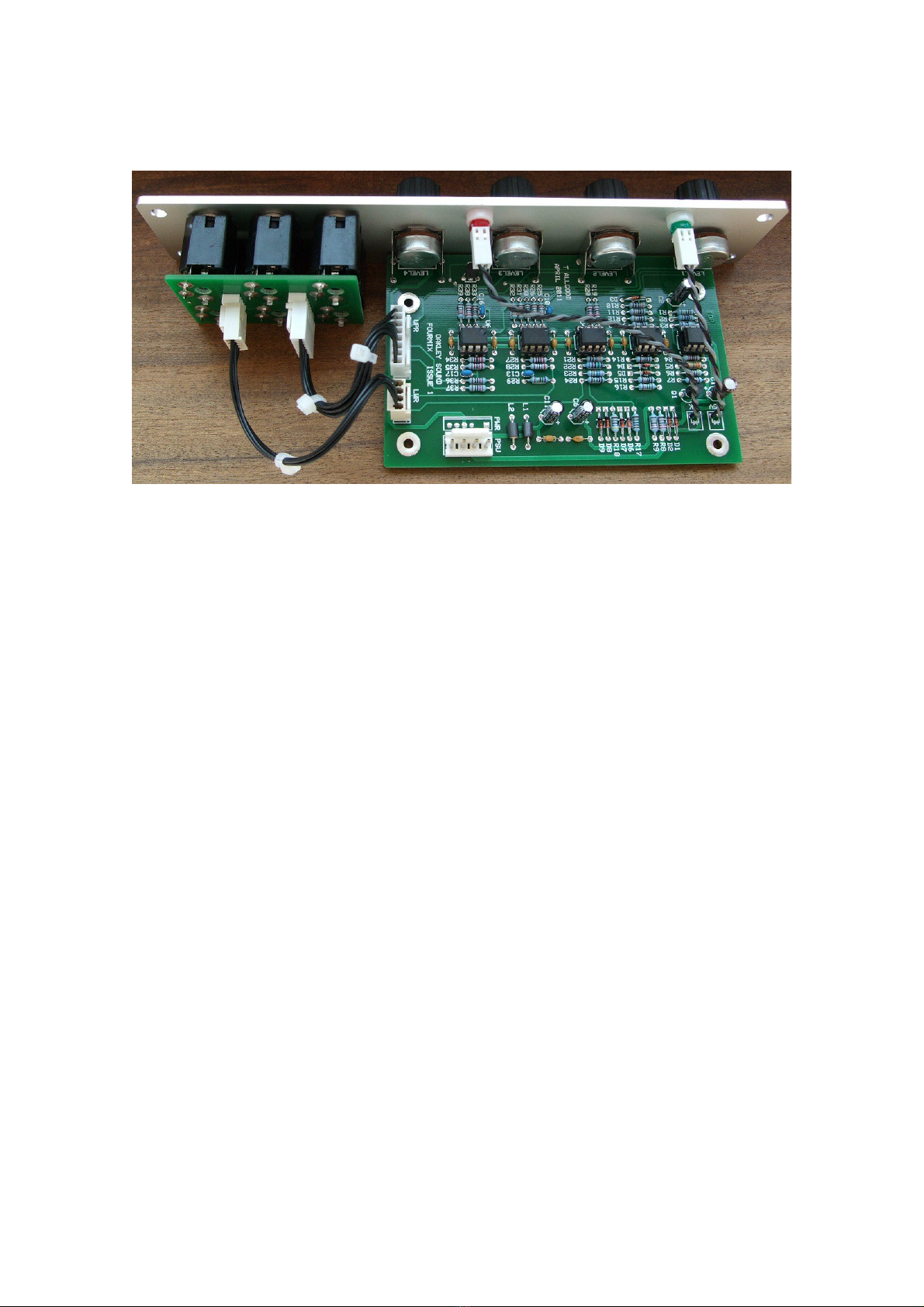
Oakley 5U User manual

Oakley Sound Systems
5U Oakley Modular Series
Fourmix
CV and Audio Mixer
Fourmix PCB Issue 1 & 2
Builder s Guide
V2.0
Tony Allgood
Oakley Sound Systems
CARLISLE
United Kingdom

Introduction
This is the Project uilder's Guide for the issue 1 and issue 2 Fourmix 5U module from Oakley
Sound. This document contains a basic introduction to the board, a full parts list for the
components needed to populate the boards, and a list of the various interconnections.
For the User Manual, which contains an overview of the operation of the unit and the
calibration procedure, please visit the main project webpage at:
http://www.oakleysound.com/fourmix.htm
For general information regarding where to get parts and suggested part numbers please see
our useful Parts Guide at the project webpage or http://www.oakleysound.com/parts.pdf.
For general information on how to build our modules, including circuit board population,
mounting front panel components and making up board interconnects please see our generic
Construction Guide at the project webpage or http://www.oakleysound.com/construct.pdf.
2

The Fourmix PC
This is the prototype issue 1 Fourmix module behind a natural finish 1U wide Schaeffer panel. Note the
use of the optional Sock6 socket board to facilitate the wiring up of the six sockets.
The issue 1 main PC is 78mm (width) x 124mm (height), and the issue 2 main PC is 75mm
(width) x 124mm (height). The board is a two layer design which means it has copper tracks
on both the upper and lower surfaces.
On the Fourmix printed circuit board there is space for the four main control pots. If you use
the specified 16mm Alpha pots and matching brackets, the PC can be held very firmly to the
panel without any additional mounting procedures. The pot spacing on this board is different
to several of our other 5U modules, instead of 1.625” it is 1.375”. Used in conjunction with
smaller 20mm or 13/16” diameter knobs this still allows for an attractive module design and
finger friendly tweaking.
The main PC has four mounting holes for M3 machine screws, one near each corner. These
are not required for panel mounting if you are using the three 16mm pot brackets.
The main board has been laid out to accept connection to our Sock6 socket board. This small
board speeds up the wiring of the six sockets and reduces the chances of building mistakes.
Power is routed onto the main PC by either a four way 0.156” MTA156 type connector or
the special five way Synthesizers.com MTA100 header.
3

Parts Lists
There are two types of Fourmix boards, issue 1 and issue 2, please ensure that you use the
right parts list for the board you have.
For general information regarding where to get parts and suggested part numbers please see
our useful Parts Guide at the project web page or http://www.oakleysound.com/parts.pdf.
The components are grouped into values, the order of the component names is of no particular
consequence.
A quick note on European part descriptions. R is shorthand for ohm. K is shorthand for kilo-
ohm. R is shorthand for ohm. So 22R is 22 ohm, 1K5 is 1,500 ohms or 1.5 kilohms. For
capacitors: 1uF = one microfarad = 1000nF = one thousand nanofarad.
To prevent loss of the small ‘.’ as the decimal point, a convention of inserting the unit in its
place is used. eg. 4R7 is a 4.7 ohm, 4K7 is a 4700 ohm resistor, 6n8 is a 6.8 nF capacitor.
Issue 1 Fourmix Parts List
Resistors
1% 0.25W metal film types are to be recommended simply because they are better quality and
lower noise components. However, 5% ones can be substituted in any of the places if you
wish. R5 will probably have to be a 5% type since getting hold of a 1% metal film resistor in
this value may be difficult.
22R R9
75R R29
120R R7, R18
470R R6
1K R17, R24
2K2 R36, R39, R37
3K R2
3K3 R21, R10
3K9 R3
11K R4, R23, R33
22K R8, R19, R20, R22, R27, R28, R35, R34, R38
33K R25, R32, R31, R30, R26
100K R12, R15, R14, R11, R13
150K R16
1M R1
3M3 R5
4

Capacitors
100nF axial ceramic C9, C3, C15, C7, C5, C12, C8, C18, C14, C4
33pF C0G 2.5mm ceramic C10, C13
100pF C0G 2.5mm ceramic C16, C17
1uF, 63V electrolytic C2
2u2, 63V electrolytic C6, C11
22uF, 35V electrolytic C1
Discrete Semiconductors
C560 PNP small signal transistor Q1
1N4148 signal diode D1, D2, D3, D4, D5
2V7 zener diode D6, D7
3V9 zener diode D8, D9
LEDs
5mm red round LED PK
5mm green round LED +5V
Two LED clips for front panel and two LED securing rings if required
Integrated Circuits
TL072ACP dual FET op-amp U3, U4, U6
OP275 or OPA2134 dual op-amp U5
LM2903 dual comparator U2
LM4040DIZ-10.0 10V reference U1*
* The LM4040CIZ-10.0 is also suitable.
Potentiometers (Pots)
All pots Alpha 16mm PC mounted types
47K or 50K linear LEVEL1, LEVEL2, LEVEL3, LEVEL4
Three 16mm pot brackets.
5

Miscellaneous
Leaded axial ferrite beads L1, L2
MTA156 4 way header PSU – Oakley/MOTM power supply
MTA100 6-way header PWR – Synthesizers.com power supply
Molex/MTA 0.1” header 8-way UPR – for connecting to sockets
Molex/MTA 0.1” housing 8-way UPR – for connecting to sockets
Molex/MTA 0.1” header 4-way LWR – for connecting to sockets
Molex/MTA 0.1” housing 4-way LWR – for connecting to sockets
Other Parts Required
Switchcraft 112APC 1/4” sockets Six off mounted either on the Sock6 board or on panel
Four 20mm or 13/16” Moog style knobs.
Four cable ties.
Around 2m of insulated multistrand hook up wire for the socket connections.
Components required if using optional Sock6 board
Molex/MTA 0.1” header 8-way UPR
Molex/MTA 0.1” housing 8-way UPR
Molex/MTA 0.1” header 4-way LWR
Molex/MTA 0.1” housing 4-way LWR
112APC Switchcraft 1/4” socket SK1, SK2, SK3, SK4, SK5, SK6
The link L1 is not to be fitted on the Sock6 PC .
If using Molex KK you'll also need at least 24 crimp terminals.
Suitable lengths of wire to make up the two interconnects and four cable ties.
6

Issue 2 Fourmix Parts List
Resistors
1% 0.25W metal film types are to be recommended simply because they are better quality and
lower noise components. However, 5% ones can be substituted in any of the places if you
wish. R5 will probably have to be a 5% type since getting hold of a 1% metal film resistor in
this value may be difficult.
22R R9
75R R29
120R R7, R18
470R R6
1K R24
2K2 R36, R39, R37
3K R2
3K3 R21, R10
3K9 R3
11K R4, R33
22K R8, R22, R23, R27, R28, R34, R35, R38
33K R25, R32, R31, R30, R26
100K R11, R12, R13, R14, R15, R19, R20
150K R16
1M R1
3M3 R5
Capacitors
100nF axial ceramic C9, C3, C15, C7, C5, C12, C8, C18, C14, C4
33pF C0G 2.5mm ceramic C10, C13
100pF C0G 2.5mm ceramic C16, C17
1uF, 63V electrolytic C2
2u2, 63V electrolytic C6, C11
22uF, 35V electrolytic C1
Discrete Semiconductors
C560 PNP small signal transistor Q1
1N4148 signal diode D1, D2, D3, D4, D5
2V7 zener diode D8, D9
5V1 zener diode D6, D7
LEDs
5mm red round LED PK
5mm green round LED +5V
7

Two LED clips for front panel and two LED securing rings if required
Integrated Circuits
TL072ACP dual FET op-amp U3, U4, U6
OP275 or OPA2134 dual op-amp U5
LM2903 dual comparator U2
LM4040DIZ-10.0 10V reference U1*
* The LM4040CIZ-10.0 is also suitable.
Potentiometers (Pots)
All pots Alpha 16mm PC mounted types
47K or 50K linear LEVEL1, LEVEL2, LEVEL3, LEVEL4
Three 16mm pot brackets.
Miscellaneous
Leaded axial ferrite beads L1, L2
MTA156 4 way header PSU – Oakley/MOTM power supply
MTA100 6-way header PWR – Synthesizers.com power supply
Molex/MTA 0.1” header 8-way UPR – for connecting to sockets
Molex/MTA 0.1” housing 8-way UPR – for connecting to sockets
Molex/MTA 0.1” header 4-way LWR – for connecting to sockets
Molex/MTA 0.1” housing 4-way LWR – for connecting to sockets
Other Parts Required
Switchcraft 112APC 1/4” sockets Six off mounted either on the Sock6 board or on panel
Four 20mm or 13/16” Moog style knobs.
Four cable ties.
Around 2m of insulated multistrand hook up wire for the socket connections.
8

Components required if using optional Sock6 board
Molex/MTA 0.1” header 8-way UPR
Molex/MTA 0.1” housing 8-way UPR
Molex/MTA 0.1” header 4-way LWR
Molex/MTA 0.1” housing 4-way LWR
112APC Switchcraft 1/4” socket SK1, SK2, SK3, SK4, SK5, SK6
The link L1 is not to be fitted on the Sock6 PC .
If using Molex KK you'll also need at least 24 crimp terminals.
Suitable lengths of wire to make up the two interconnects and four cable ties.
9

Connections
Power connections – MOTM and Oakley
The PSU power socket is 0.156” Molex/MTA 4-way header. Friction lock types are
recommended. This system is compatible with MOTM systems.
Power Pin number
+15V 1
Module ground (0V) 2
Earth/PAN 3
-15V 4
Pin 1 on the I/O header has been provided to allow the ground tags of the jack sockets to be
connected to the powers supply ground without using the module’s 0V supply. Earth loops
cannot occur through patch leads this way, although screening is maintained.
Power connections – Synthesizers.com
The PWR power socket is to be fitted if you are using the module with a Synthesizers.com
system. In this case you should not fit the PSU header. The PWR header is a six way 0.1”
MTA, but with the pin that is in location 2 removed. In this way location 3 is actually pin 2 on
my schematic, location 4 is actually pin 5 and so on.
Power Location number Schematic Pin number
+15V 1 1
Missing Pin 2
+5V 3 2
Module ground (0V) 4 3
-15V 5 4
Socket ground* 6 5
+5V is not used on this module, so location 3 (pin 2) is not actually connected to anything on
the PC .
If fitting the PWR header and using it with a standard MU power distribution system, you will
also need to connect together the middle two pads of the PSU header on the main board. This
link connects the socket and panel ground with the module ground. Simply solder a solid wire
hoop made from a resistor lead clipping, or bit of solid core wire, to join to the two middle
pads of PSU.
* Issue 2 Fourmix main boards now connect the unused pin 6 of the MU connector to socket
ground. With the link on PSU not fitted, and using an Oakley MU Dizzy distribution board
10

with a five way power cable, allows the socket ground to be kept separate from module
ground to prevent ground loops.
Building the Fourmix module using the Sock6 board
This is the simplest way of connecting all the sockets to the main board. The Sock6 board
should be populated in the way described in our construction guide found on the project
webpage. There are only two headers, UPR (for upper) which is eight way, and LWR (for
lower) which is four way. oth headers are fitted to the bottom side of the board.
The wire link L1 must not be fitted on the Sock6 board.
You need to make up two interconnects. The eight way one should be made so that it is 95mm
long. The four way should be made to be 110mm.
The Fourmix prototype module showing the detail of the board to board interconnect. ere I have used
the Molex KK 0.1” system to connect the Sock6 to the main PCB.
11

Hand wiring the sockets
If you have bought Switchcraft 112A sockets you will see that they have three connections.
One is the earth or ground tag. One is the signal tag which will be connected to the tip of the
jack plug when it is inserted. The third tag is the normalised tag, or NC (normally closed) tag.
The NC tag is internally connected to the signal tag when a jack is not connected. This
connection is automatically broken when you insert a jack.
Once fitted to the front panel the ground tags of each socket can be all connected together
with solid wire. I use 0.91mm diameter tinned copper wire for this job. It is nice and stiff, so
retains its shape. A single piece of insulated wire can then be used to connect those connected
earth tags to pin 1 of LWR. Pin 1 is the square solder pad.
All the other connections are connected to the signal or NC lugs of the sockets. The tables
below show the connections you need to make:
UPR
Pin Pad name Socket Connection Lug Type
Pin 1 Module ground IN2 NC
Pin 2 IN2 IN2 Signal
Pin 3 -5V IN4 NC
Pin 4 IN4 IN4 Signal
Pin 5 +5V IN3 NC
Pin 6 IN3 IN3 Signal
Pin 7 Module ground IN1 NC
Pin 8 IN1 IN1 Signal
LWR
Pin Pad name Socket Connection Lug Type
Pin 1 Panel ground Connects to all sockets Ground lugs
Pin 2 OUT_SOFT OUT (SOFT) Signal
Pin 3 Not Connected
Pin 4 OUT_MAIN OUT (MAIN) Signal
12

Testing
Apply power to the unit making sure you are applying the power correctly. Check that no
device is running hot. Any sign of smoke or strange smells turn off the power immediately and
recheck the polarity of the power supply, and the direction of the ICs in their sockets and the
polarity of the electrolytic capacitors. Current consumption should be around +25mA and
-22mA. Anything significantly more than this, say +/-35mA, would indicate a problem.
The next thing to do is to make sure that the internal voltage references are working correctly.
Measure the voltage with respect to ground from the MAIN (OUT) socket. With all the front
panel pots turned to their minimum value the output voltage should be close to zero volts give
or take a few millivolts. Now turn up LEVEL3 to its maximum setting. The voltage should
now be at just under +4.7V. The +5V green LED may possibly come on but the PK red LED
should remain off. Now keeping LEVEL3 still at its maximum setting turn LEVEL4 up to its
maximum setting too. The output voltage should now fall to very close to zero volts again
give or take a few mV. Now reduce LEVEL3 to its minimum value and the output voltage
should drop to -4.7V. Turn LEVEL4 down to its minimum value and the voltage should again
drop to zero volts.
Now send an audio signal into IN1. Check that by turning up the LEVEL1 pot you can
control the signal level heard at OUT (MAIN) and OUT (SOFT). Repeat this procedure for
the other three input channels.
Using a triangle wave signal into IN1 check that the SOFT (OUT) produces a soft clipping
effect. If you use a 440Hz triangle wave signal you should be able to hear the difference as
you turn the input level pot up. Not only will you hear a change in output volume you will also
hear the triangle wave's higher harmonics become more muted. At the top of the pot's travel
the triangle wave will sound almost sine like. If you have a oscilloscope (or a waveform
monitor on your computer DAW) you can see the effect in action.
Using a 'mult' or multiple module connect the first three inputs of the Fourmix to one single
signal source. The triangle wave signal is perfect for this. Check that with LEVEL1 turned up
full and LEVEL2 just turned up slightly the +5V LED glows green. Turning LEVEL2 up all
the way and then having LEVEL3 turned slightly up should activate the red PK LED. The
sensitivity of the LEDs switching circuits are determined by your power supply voltages so
you may find your LEDs may need slightly more or less signal to be activated.
If all this happens, the chances are that you have a working module.
13

Final Comments
If you have any problems with the module, an excellent source of support is the Oakley Sound
Forum at Muffwiggler.com. I am on this group, as well as many other users and builders of
Oakley modules.
If you can't get your project to work and you are in the EU, then Oakley Sound Systems are
able to offer a 'get you working' service. If you wish to take up this service please e-mail me,
Tony Allgood, at my contact e-mail address found on the website. I can service either fully
populated PC s or whole modules. You will be charged for all postage costs, any parts used
and my time at 25G P per hour. Most faults can be found and fixed within one hour, and I
normally return modules within a week. The minimum charge is 25G P plus return postage
costs.
If you have a comment about this builder's guide, or have a found a mistake in it, then please
do let me know. ut please do not contact me directly with questions about sourcing
components or general fault finding. Honestly, I would love to help but I do not have the time
to help everyone individually by e-mail.
Last but not least, can I say a big thank you to all of you who helped and inspired me. Thanks
especially to all those nice people on the Synth-DIY and Analogue Heaven mailing lists and
those at Muffwiggler.com.
Tony Allgood at Oakley Sound
Cumbria, UK
© April 2011 – updated June 2020
No part of this document may be copied by whatever means without my permission.
14
Other manuals for 5U
3
Table of contents