OCEANAIRE OWC series Manual

ENGINEERING, INSTALLATION AND SERVICE MANUAL
OWC series
Deluxe Portable Water-Cooled Spot Cooler
Form EISM-OWC, 110114 Rev 1

TABLE OF CONENTS PAGE
GENERAL DESCRIPTION …................................. 1
PRODUCT DATA AND SPECIFICATIONS............ 2
UNIT DESCRIPTION
Standard Features.................................. 3
Applications / Operation.......................... 4
Electrical.................................................. 5
Use of Extension Cords........................... 6
Accessories………................................... 7 - 12
Options..................................................... 13
Installation................................................ 14
Electronic Controller................................. 15 - 17
SERVICE
Water Valve Adjustment, Unit Interior..... 18
Replacement Parts Procedure................. 19
Troubleshooting Guide............................. 20
Preventive Maintenance........................... 21
DIAGRAMS
Piping Schematic....................................... 22
Three Phase Monitor................................. 23
Wiring Diagrams......................................... 24 - 29
FORWARD
This manual provides the user with basic details for the installation
and operation of the Oceanaire Air Boss spot cooler. It is recom-
mended to read and fully understand the instructions outlined within
this manual, before operating the AQUACOOLER unit.
As with all commercial air conditioning equipment, it is recommended
to have the AQUACOOLER sized and installed by a licensed specify-
ing engineer and contractor, in accordance with all local and state
codes. The length of service received can be extended by following
the installation and preventive maintenance instructions.
NOTICE
In our ongoing process of continuous improvement, the items and
procedures described in this manual are subject to change without
notice. Please note model and serial number of the AQUACOOLER
unit when contacting the factory.

NOMENCLATURE
O WC 24 1 2
DELUXE
PORTABLE VOLTAGE
WATER-COOLED SINGLE PHASE
NOMINAL CAPACITY
CAPACITY RATING SUFFIXES
12..........12,000 BTU/HR 5—50 Hz Model
18..........18,000 BTU/HR H—Heresite® Coated Coil
24..........24,00 BTU/HR QC—Quick Connect Fittings
36..........36,000 BTU/HR S—Special Model
60……...60,000 BTU/HR
GENERAL DESCRIPTION
The Oceanaire AQUACOOLER is a portable water-cooled air condi-
tioner designed for permanent or temporary spot cooling applica-
tions. The entire air conditioning unit has been built in an attractive
sheet metal cabinet, equipped with heavy-duty casters for mobility.
All AQUACOOLER models come with a 10-foot power cord for elec-
trical connection and added mobility in service. These spot-coolers
are designed to direct air to specific areas or objects through a dis-
charge grill located on the upper-front of the unit, while rejecting heat
from the top of the unit. The AQUACOOLER models range in cool-
ing capacities from 12,000 BTU/HR to 60,050 BTU/HR to satisfy
most space cooling requirements.
The AQUACOOLER is a self-contained unit with the entire cooling
system, fan motors and water-side components neatly arranged in a
gray polyester powder coated metal cabinet. When connected to the
proper source of electrical power, the digital thermostat controls the
AQUACOOLER unit to provide the desired level of comfort and cool-
ing.
A wide variety of accessories and factory installed options are availa-
ble for the AQUACOOLER units allowing for improved performance
and versatility.
WARRANTY CARD
It is important that the warranty card be filled out completely and
returned to the factory within fourteen (14) days of installation of the
unit in order to receive the benefits of the warranty.
1

2

STANDARD FEATURES
CABINET
The OWC-Series cabinet is constructed of 18 gauge steel with a gray polyester powder
coated finish that will compliment any decor. The entire cabinet is insulated with a sound-
absorbing insulation for cool, quiet comfort. All units come equipped with swivel casters
for portability and convenient set-up.
ELECTRONIC THERMOSTAT
All AQUACOOLER units are equipped with a non-programmable electronic thermostat.
When power is connected to the unit, the thermostat will control the unit to cool a space to
the desired temperature. The thermostat is also capable of controlling the fan to operate
automatically (when needed) or continuously. To protect the compressor from short-
cycling, there is a built-in time delay in the thermostat. In the event of a power outage, all
thermostat settings are saved, and the unit will re-start automatically.
FAN SPEED CONTROL
The electronic thermostat is capable of setting fan speeds automatically or manually. In
AUTO mode, the fan speed adjusts in according to cooling conditions. In MANUAL
mode, the fan speed can be maintained at a one of six speed levels, from low to high.
CONDITION ALARM—CON
The LED thermostat of the AQUACOOLER will display the word “CON”, indicating a fault
condition in the controller. CON indicates that there is a condensate condition that needs
to be addressed or the high pressure switch has been tripped. For models less than 5-
tons, the CON indicates that the condensate tank is full and needs to be emptied. In the 5
-ton AQUACOOLER units (model OWC60) CON indicates a condensate pump over-flow
condition where the pump is either disabled, or incapable of rejecting the condensate
water, and must be serviced. For the high pressure switch, see below.
CONDENSATE PUMP
All AQUACOOLER units come equipped with an Automatic Condensate Pump that dis-
poses of the condensate. The pump discharges through a 3/8 male flare DRAIN connec-
tion located on the back of the unit. The automatic pump is capable of a 20ft lift, to han-
dle almost about any installation requirement.
HIGH PRESSURE SAFETY SWITCH—CON
Located on the back of the AQUACOOLER unit is a manual re-set high pressure switch,
used for the protection of the compressor in the event that the condenser water supply is
turned off. If the condensing pressure exceeds the limit setting, the cut-out shuts down
the compressor, while the evaporator fan remains running, and “CON”will display on the
controller. Once the water interruption has been corrected, turn the unit off, reset the
switch by depressing the red RESET button on the back of the unit, and restart the unit.
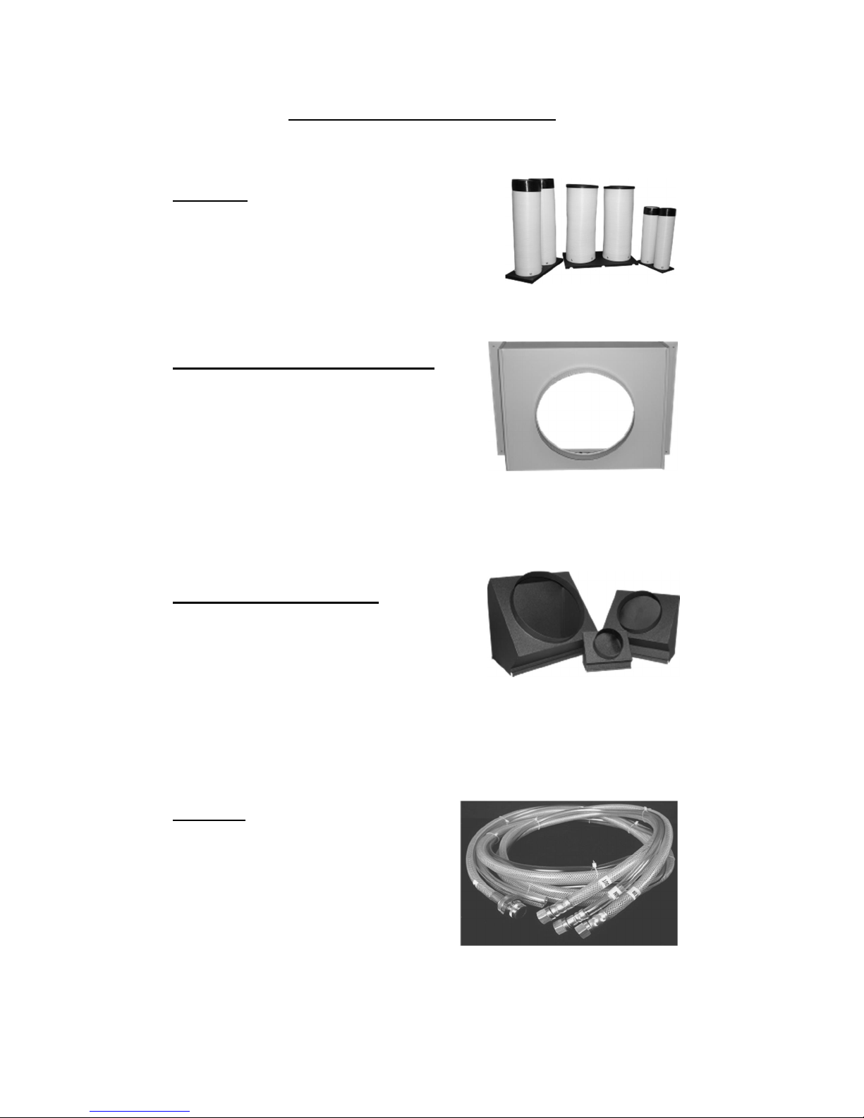
FILTERS
All AQUACOOLER units are equipped with washable a filter at the air intake. Electrostatic
mesh air filters located behind the evaporator return air grill serve to filter the air before it
is cooled, keeping the coil free from dust build-up. The filters can be easily removed and
cleaned.
POWER CORDS
All AQUACOOLER units come with power cords, convenient connection and portability.
All units except the 5-ton models, and 3-phase models are equipped with LCDI for added
safety devices.
3

4
APPLICATIONS
SPOT COOLER
The AQUACOOLER can be used in an open environment to cool specific
objects or "spots". Spot Cooling is a convenient and economical way to
provide air conditioning where cooling the entire space is impractical. Cool
air is discharged from the unit and is directed where it is needed. Nozzle kits
can be used to improve direction of the cooling airflow.
ROOM AIR CONDITIONER
One feature of the AQUACOOLER is it operates as a room air conditioner
because water is used as the means for heat rejection. The major
convenience of water-cooled air conditioning is the convenience of
connecting water hoses or lines as compared to the installation of condenser
air ducts used for air-cooled portables. A variety of hose kits are available
that can be used for connecting to a water supply and drain while providing
portability within the conditioned space.
AQUACOOLER—OPERATION / DESCRIPTION
AQUACOOLER—FRONT VIEW
RETURN
AIR
INLET
EVAPORATOR
FAN DISCHARGE
“COOL”
GRILL
AND FILTER
ELECTRONIC
THERMOSTAT
DRAIN
WATER IN
WATER OUT

SERVICE CORD
All AQUACOOLER Series units are equipped with the standard ten foot long service cord
with plug configurations and receptacle requirements as shown in this chart. OWC1211,
OWC1811, OWC2412 and OWC3612 units come with LCDI (Leakage Current Detection
& Interruption) devices that serve as a means of electrical protection.
CAUTION—DO NOT USE THE LCDI AS AN ON/OFF SWITCH FOR THE UNIT
All 3-phase models are equipped with locking plugs for added connection reliability. Re-
fer to the chart below for plug and receptacle details for all AQUACOOLER models.
A DAMAGED LCDI POWER SUPPLY CORD MUST BE REPLACED
WITH A NEW POWER SUPPLY CORD OBTAINED FROM OCEAN-
AIRE, AND NOT REPAIRED
UNIT/MODEL PLUG CONFIGURATION RECEPTACLE
115 VOLT
OWC1211
OWC1811
NEMA-5-15R
208-230 VOLT SINGLE PHASE
OWC2412
OWC3612
NEMA 6-20R
208-230 VOLT SINGLE PHASE
OWC6012
NEMA 6-50R
208-230 VOLT 3-PHASE
OWC3632
NEMA L15-20R
208-230 VOLT 3-PHASE
OWC6032
NEMA L15-30R
460 VOLT 3-PHASE
OWC3634
OWC6034
NEMA L16-20R
15A-125 VOLT
NEMA 5-15P
20A-250 VOLT
NEMA 6-20P
30A-250 VOLT
NEMA 6-30P
20A-250 VOLT
NEMA L15-20P
30A-250 VOLT
NEMA L15-30P
20A-460 VOLT
NEMA L16-20P
5

6
USE OF EXTENSION CORDS
CAUTION:
FOR MODEL OWC1211 AND OWC1811 AN EXTENSION CORD CAN BE
USED PROVIDED IT IS RATED AT LEAST 15 AMPS @ 115 VOLTS WITH
GROUNDING-TYPE ATTACHMENT PLUG AND GROUNDING TYPE
CONNECTOR (LOAD FITTING)
FOR MODELS OWC2412 and OWC3612 AN EXTENSION CORD CAN BE
USED PROVIDED IT IS RATED AT LEAST 20 AMPS @ 250 VOLTS WITH
GROUNDING-TYPE ATTACHMENT PLUG AND GROUNDING TYPE
CONNECTOR (LOAD FITTING)
FOR MODEL OWC6012 AN EXTENSION CORD CAN BE USED PROVID-
ED IT IS RATED AT LEAST 30 AMPS @ 250 VOLTS WITH GROUNDING-
TYPE ATTACHMENT PLUG AND GROUNDING TYPE CONNECTOR
(LOAD FITTING)
FOR MODEL OWC3632 AN EXTENSION CORD MAY BEUSED PROVID-
ED IT IS RATED AT LEAST 20 AMPS @ 250 VOLTS, 3 PHASE
FOR MODELS OWC6032 AN EXTENSION CORD MAY BEUSED PRO-
VIDED IT IS RATED AT LEAST 30 AMPS @ 250 VOLTS, 3 PHASE
FOR MODELS OWC3634 AND OWC6034 AN EXTENSION CORD CAN
BE USED PROVIDED IT IS RATED AT LEAST 20 AMPS @ 600 VOLTS, 3
PHASE
SPECIAL NOTICE—THREE PHASE OPERATION
Models OWC3632, OWC3634, OWC6032 and OWC6034
All three-phase AQUACOOLER models are equipped with a three-
phase monitor for added compressor protection. The phase monitor,
located in the control box, has multi-color LED that reports status.
The monitor protects the compressor from reverse operation, phase
loss and low voltage situations. Further description of the three-
phase monitor is located in the electrical section of the manual.
NOTICE - DO NOT OPERATE ANY THREE-PHASE UNIT BY BY-
PASSING THE MONITOR, THIS WILL VOID THE WARRANTY

7
AQUACOOLER UNIT
ACCESSORIES

8
OWC –AQUACOOLER ACCESSORIES
NOZZLE KIT
NK-1 (2 X 4-Inch) OWC12
NK-2 (2 X 6-Inch) OWC18, 24
2NK-3 (2 x 8-iNCH) OWC36
NK-3 (2 X 8-Inch) OWC60
EVAPORATOR RETURN AIR PLENUM
DEP-10 (10-Inch Round) OWC12
DEP-12 (12-Inch Round) OWC18, 24, 36
DEP-16 (16-Inch Round) OWC60
DISCHARGE DUCT ADAPTER
DDA-6 (6-Inch Round) OWC12
DDA-10 (10-Inch Round) OWC18, 24,
2DDA-16 (16-inch Round) OWC36
DDA-16 (16-Inch Round) OWC60
HOSE KIT
HK-1 10FT OWC 12, 18, 24
HK-2 25FT OWC 12, 18, 24
HK-5 40FT OWC 12, 18, 24
HK-3 10FT OWC 36, 60
HK-4 25FT OWC 36, 60
HK-6 40FT OWC 36, 60

ACCESSORIES
DISCHARGE AIR NOZZLE KIT ASSEMBLY (NK, 2NK)
The optional discharge nozzle kits are used to direct the conditioned air to a specific tar-
get area. By concentrating the airflow, the nozzles increase the air velocity towards
production lines to cool personnel or equipment. In server rooms, the nozzles can be
used to induce airflow through the rack to remove the hot air from the area of the equip-
ment.
NK-1 for model OWC12, with (2) 4-inch diameter nozzles with an approximate
compressed length of 15 inches. The approximate extended length is 21 inches.
NK-2 for models OWC18 and OWC24 with (2) 6-inch diameter nozzles with an
approximate compressed length of 22 inches. The approximate extended length is
32 nches.
2NK-3 for model OWC36 , with (2) 8-inch diameter nozzles with an approximate
compressed length of 20 inches. The extended length is approximately 29 inches.
NK-3 for OWC60, with (2) 8-inch diameter nozzles with an approximate compressed
length of 20 inches. The extended length is approximately 29 inches.
The nozzle kits come pre-assembles with the nozzles secured to a mounting plate, and
with edge guards. By removing the AQUACOOLER discharge grill, one can insert the
nozzle kit into the opening without the use of tools.
Nozzle Kits
9

ACCESSORIES
EVAPORATOR RETURN AIR PLENUM, DEP
Evaporator return air plenums are available for installations where it is required to duct air
to the inlet of the evaporator. The evaporator return air plenums allow the user to connect
round duct (flexible or rigid) to the return air intake to reduce air noise and increase the
number of options for solving difficult cooling problems. The plenum attaches to the front
of the unit, replacing the return air grill. Refer to the table below for configuration and
application information
DEP-10 for OWC12 transitions the return air opening to a 10-inch round duct.
DEP-12 for OWC18 and OWC24 transitions the return opening to a 12-inch round
duct.
DEP-16 for OWC36 and OWC60 transitions the return opening to a16- inch round
duct.
NOTE—When a DEP is installed, it is recommended to set the evaporator blower
speed to high, to avoid evaporator freeze-up.
Plenum Kit
Duct/Flange OWC12 OWC18 OWC24 OWC36 OWC60 FILTERS
DEP-10
10 inch ü (1) 10”X20”X1”
DEP-12
12 inch ü ü (1) 15”X25”X1”
DEP-16
16 inch ü ü (1) 12”X30”X1”
(1)15”X30”X1”
Maximum
Equivalent Feet 25 50 50 50 100
Est. External
Static
Pressure (.20) (.25) (.25) (.25) (.50)
FILTER(S)
DEP—EVAPORATOR
RETURN AIR PLENUM
10

ACCESSORIES
Discharge Duct Adapter, DDA
Discharge duct adapters are available for applications where ducted evaporator discharge
is required. The adapters can be easily installed on the unit without fasteners, and be
installed for either vertical or horizontal ducting. The standard discharge grille is removed
and the DDA is attached in the grill opening.
DDA-6 for OWC12, converts the evaporator discharge to a 6-inch diameter round
duct.
DDA-10 for OWC18 and OWC24, converts the evaporator discharge to a 10-inch
diameter round duct.
2DDA-16 for OWC36, converts the evaporator discharge to a 16-inch round duct.
DDA-16 FOR OWC60, converts the evaporator discharge to a 16-inch round duct.
When used in conjunction with the evaporator return air plenum, DEP, the unit can pro-
vide closed-loop cooling to and from a given space without the influence of any outside
air.
NOTE—When a DDA is installed, it is recommended to set the evaporator blower
Adapter
Model Round
Duct Size OWC12 OWC18 OWC24 OWC36 OWC60
DDA-6 6-inch ü
DDA-10 10-inch üü
DDA-16 16-inch ü
Maximum Approx
Equivalent Feet 25 50 50 50 100
Maximum
E.S.P .15 .25 .25 .25 .50
2DDA-16 16-inch ü
11

ACCESSORIES
Hose Kit, HK
Hose kits are available in lengths of 10, 25, and 40 feet. Each hose kit allows for conven-
ient installation of the AQUACOOLER, while allowing for portability within the allowable
space.
NOTICE—When using these hoses in applications with water pressures exceeding
50 PSIG, a water pressure reducing valve must be installed in the water supply line
prior to the hose kit; otherwise warranty on the hose kits will be void.
All hose kits have FEMALE flare connectors to match the MALE flare fittings on the units
(see chart below). The WATER IN connector consists of a 3/4”hose barb. WATER OUT
and DRAIN (condensate) have no fitting, and can be fed to a sink or permanent drain.
When using a hose kit, avoid sharp corners, hot water pipes and kinking to assure proper
water flow of the supply and return lines.
Included with the hose kit is a sink/faucet adapter
Hose Kit
Hose Kit Length Flare Conn
IN-OUT-DRAIN OWC12 OWC18 OWC24 OWC36 OWC60
HK-1 10 ft 3/8 3/8 3/8 üüü
HK-2 25 ft 3/8 3/8 3/8 üüü
HK-5 40 ft 3/8 3/8 3/8 üüü
HK-3 10 ft 5/8 5/8 3/8 üü
HK-4 25 ft 5/8 5/8 3/8 üü
HK-6 40 ft 5/8 5/8 3/8 üü
12

13
OPTIONS
In some applications, units can be manufactured with optional components
for added performance and longevity. Below are a few of the AQUA-
COOLER options that are available for units.
Consult your distributor for pricing and availability.
TOWER UNITS
In applications where the AQUACOOLER is connected to a closed-loop
condenser water circuit, a unit can be built for direct water connection
without a water valve.
HIGH PRESSURE WATER VALVE
For applications where water supply pressures exceed 150 psig, a high
pressure water regulating valve can be installed in the AQUACOOLER.
Valves designed for use with up to 350 psig water inlet pressure, are avail-
able.
CUPRO-NICKEL CONDENSER
When chemically treated water, salt water or brine is used in the conden-
ser coil, it is recommended that the AQUACOOLER be equipped with a
90/10 Cupro-Nickel condenser coil.
ACRYLIC TREATED EVAPORATOR COIL
When airborne contaminants are a problem for air conditioning applica-
tions, acrylic coated evaporator coils are recommended to guard against
pitting or corroding.
HERESITE TREATED EVAPORATOR COIL
For use in chemically corrosive environments, the AQUACOOLER can be
manufactured with a Heresite® coated evaporator coil for improved coil
life.
HOT GAS BYPASS VALVE
In applications where low evaporator temperatures may occur, an optional
hot gas bypass valve can be installed to regulate the evaporator tempera-
ture. The bypass valve feeds refrigerant (hot gas) into the evaporator to
avoid freeze-ups.

INSTALLATION INSTRUCTIONS
RECEIVING—INSPECTION:
Upon receiving your AQUACOOLER unit, inspect the packaging for any
damage. All units are shipped on a skid, and packaged in a triple-wall
carton for added protection. In shipment, some wear may occur on the
packaging. If the packaging is heavily damaged or broken, file a claim
with the freight company immediately. Carefully unpack the unit
and remove all wrapping materials. Save all documentation and fill out
the Warranty Card and mail it to Oceanaire.
BEFORE INSTALLING
Check the air conditioner/spot cooler for any damage. All Oceanaire
products are thoroughly inspected at the factory and carefully
packaged. If any damage is evident, file a claim with the delivering
carrier immediately.
ELECTRICAL REQUIREMENTS
Check the nameplate located on the back of the unit to make certain
that the proper power is available for the unit. Refer to "Specifications"
section for voltage and amperage requirements. For proper NEMA
receptacles, refer to "Electrical service plug configuration". When using
extension cords, use the properly sized cord, and check cord voltage to
the unit.
TIME DELAY FUSES/CIRCUIT BREAKERS ARE RECOMMENDED
WARNING—OPERATING THE UNIT ON
IMPROPER VOLTAGE WILL VOID THE
WARRANTY
ACCESSORIES
Verify that all accessories are correct for the model, and that they
installed in accordance with all instructions.
START-UP
Install the unit in accordance with all local and state building codes, and
install all accessories. Allow for a clearance around the unit for future
maintenance and/or service. Level unit and lock casters, when
available. Connect power and test the LCDI on the power cord (if
available). Power up unit, via thermostat and check for proper
operation. Refer to Thermostat Operation for more details.
14

15
Deluxe Electronic Controller
The AQUACOOLER controller is equipped with many features for a more precise level of
cooling and operation. Additionally, the controller can be removed from the unit and in-
stalled for remote operation when using an extended display cable. Also, with the
addition of a remote sensor, the controller can operate from the unit while sensing
temperatures in another space or in ductwork —accessory parts may be required.
OCEANAIRE DELUXE ELECTRONIC CONTROLLER DISPLAY
When power is connected, the controller will display “888”momentarily, and will then go
blank. Press the POWER button, then press the TEMP SELECT button until the SET
POINT is displayed. Adjust the SET POINT to the desired temperature, and the unit will
heat/cool as required.
The systems controls temperature within +/- 2°
POWER—Turns the unit on/off when power is supplied
MODE - Selects the mode of operation between Cool and Moisture Control.
COOL - The system will operate in cooling mode, only.
MOISTURE CONTROL - The system operates in the cooling mode to reduce humidity
within the conditioned space.
Every 4 hours, the fan is started, circulating the air, and the air temperature is recorded by
the controller. The cooling cycle is started for one hour, or until the room temperature
drops 2°, which ever comes first. This cycle repeats every four hours.

16
FAN SPEED—The operator can select between AUTO and MANUAL fan speed control.
Pressing the FAN SPEED button, will switch speed from AUTO to MANUAL. In MANUAL
mode, pressing the FAN SPEED button will change fan speed from low to high. In AUTO
the fan speed is controlled automatically. In cooling mode, the controller automatically
adjusts the fan speed to high, and as the inside temperature approaches the set point, the
fan speed will reduce. In heat mode, the fan speed goes from low to high as the tempera-
ture approaches the set point
TEMP SELECT—Allows the operator to view the controller temperatures; INSIDE = re-
turn air temperature, OUTSIDE = supply air temperature, SET POINT can be seen and
adjusted, by pressing ▲or▼.
CONTROLLER PROGRAMMING MENU
1) Make sure the unit has power.
2) Pushing the POWER button, turn the unit “OFF”.
3) Press the following buttons in sequence “S-U-D-S”:
4) The display will begin flashing P1 and a number.
If there is no display, repeat the sequence, making sure the unit has power, but is turned
OFF.
5) To adjust any program parameter, press the ARROW UP▲or ARROW DOWN ▼
button until the desired value is displayed.
6) Use the “MODE”button to scroll through the programmable parameters P1 through
P16.
7) If no buttons are pushed, the display will then return to the “OFF”position after about
50 seconds.
PROGRAMMING PARAMETERS
P1—High Fan Speed Limit Setting
P2—Low Fan Speed Limit Setting
P4—Temperature Sensor Calibration
P10—Temperature Display, °F or °C
P13—Supply Fan Operation, Cycling or Continuous
P15—Fan Motor Type Setting, PSC or Shaded Pole
7) To cycle the evaporator fan with the compressor, access code P-P1, P2 - To adjust fan
speed settings, P1 represents the high fan speed parameter, while P2 represents the low
fan speed parameter. When using nozzle kits, discharge duct adapters and evaporator
plenums, setting P1 to 85 will help to avoid freeze ups.
P4 - Adjust the P4 setting to match the actual INSIDE room temperature, if needed.
P10 - Use this parameter to display temperatures in the desired units.
P13 - To cycle the evaporator fan with the compressor, access code P-13. Press the up
or down button to switch to “CYC”, which means cycle the fan with the compressor. The
factory default setting is “CON”, which means continuous fan operation.
P15 - Fan Motors are PSC type, SC - should be selected.
8) Press POWER—you should see a code A (followed by numbers)
Press POWER and the unit will start at the new settings

TO CHECK THE NUMBER OF HOURS ON THE UNIT
1) Disconnect unit power, and reconnect unit power.
2) When “888”appears in display, push and release the arrow down
button
3) The first set of numbers displayed reads thousands of hours:
02 = 2000, 04 = 4000 hours, 00 means less than 1000 hours.
4) The second set of numbers read hours directly:
58 = 58 hours. 742 = 742 hours.
6) Add the 2 number sets together to get total hours.
03 and 486 = 3486 hours. 01 and 59 = 1059 hours.
“TOTAL HOURS”REPRESENTS COMPRESSOR “RUN”TIME
MODEL CODE SETTINGS
OWC12 P1 = 85, P2 = 35
OWC18 P1 = 80, P2 = 50
OWC24 P1 = 70, P2 = 50
OWC36 P1 = 85, P2 = 40
OWC60 P1 = 85, P2 = 45
AQUACOOLER PROGRAM PARAMETERS
NOTICE
Program Parameters are NOT controller default values.
They are Oceanaire Factory Settings
DISPLAY FAULTS
LAC……. Low AC line power
AAA…….Failed Air Sensor (unit will not run)
CON…….Empty Condensate Bucket—Units with a bucket
Condensate Pump Over-Flow Alarm—Units with pump
High Pressure Cut-Out—Low condenser water supply
correct problem, and re-set unit at HP RESET
17

WATER VALVE ADJUSTMENT
All AQUACOOLER units come equipped with automatic pres-
sure regulated water valves, that control the condenser water
flow rate. The water valves will open when the system is
running and will adjust the water flow rate as required by the
air conditioning system.
In some cases, water temperatures can cause the valve to
open and close at a high rate, causing a “chattering”condition
in the water supply line. In these cases, it is recommended
that the water valve be adjusted.
1. Disconnect the unit power.
2. Remove the unit back panel and locate the water regulat-
ing valve in the lower right region of the unit.
3. Locate the water valve adjustment screw. At the top of the
valve there is a square-shaped adjustment screw.
4. Turn the adjustment screw 1/4 turn, re-start the unit, and
observe operation to see if the “chattering”goes away. Make
1/4 turn adjustments and observe the unit operation until the
condition goes away.
5. Close up the unit and POWER
18
Water Valve
Adjustment
Screw
OWC INTERIOR
Table of contents
Other OCEANAIRE Freezer manuals
Popular Freezer manuals by other brands

Emerson
Emerson CF353 owner's manual

Frigidaire
Frigidaire FFC07M5HW0 Factory parts catalog

Zanussi
Zanussi ZFT610X Instruction book

NEW BRUNSWICK SCIENTIFIC
NEW BRUNSWICK SCIENTIFIC Innova Series Guide to operations

Electrolux
Electrolux erb 29003 w8 user manual

Frigidaire
Frigidaire FFU21M7HW - 20.7 cu. ft. Manual Defrost Upright... Features & dimensions