ODES UTVS 2015 Raider User manual

RAIDER
ASSEMBLY
INSTRUCTIONS
Model Year: 2015
Model Engine Size Category
2 Door 800cc/1000cc Off-road
IMPORTANT INFORMATION
The assembly instructions in this guide are for the Raider models only. Please make sure a PDI was
performed on each unit before the assembly begins.
ALSO
• Do PDI with customer before unit leaves.
• Fill out proper warranty registration completely with customer (explain to them in detail what cover-
age they have.)
• Submit to ODES within 5 days.
• Go over maintenance charts with customer.

Uncrating/ Removing Parts
1-1
Carefully remove the tarp and plastic wrap
covering the crate.
Pop off all of the tabs from the crate bars.
Once all tabs are removed the crate bars
will fold open and you can begin removing
them.

Uncrating/ Removing Parts
1-2
Once you have fully uncrated your Raider,
you can begin to remove all loose parts.
There are loose parts on the inside, frame
and underneath the unit, please be sure to
remove everything.
The fender ares will be zip tied to the rear
fender area.

Bottom Plate Removal
Lift the Raider slighty off the ground to
begin unbolting the bottom plate of the
crate.
Unbolt the brackets on all 4 hubs to de-
tach the Raider from the bottom plate.
Once all hubs are unbolted, you can now
lift the Raider higher and begin putting on
the shocks.

Toolbox/ Bolt Bags
The bolt bag is located underneath the
passenger side seat plate.
Remove the plate and toolbox cover. Once
removed, you can begin removing the bolt
bags from the toolbox.
Be sure all bags are accounted for, a bolt
bag form should come with your UTV. If
you cannot locate the bolt bag form, you
can download it on our website www.
odesutvs.com underneath SUPPORT > My
Dealer Services.

Shocks 1-1
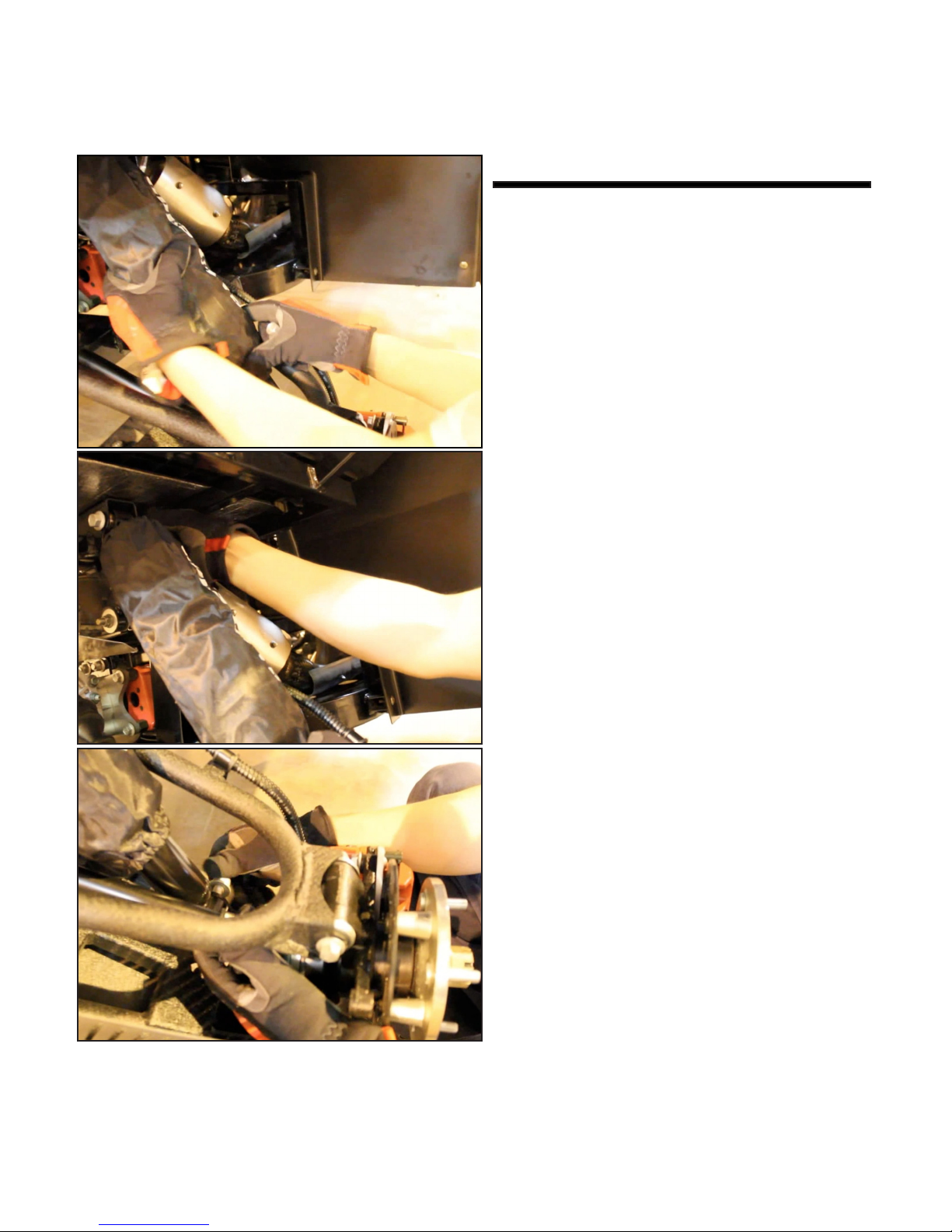
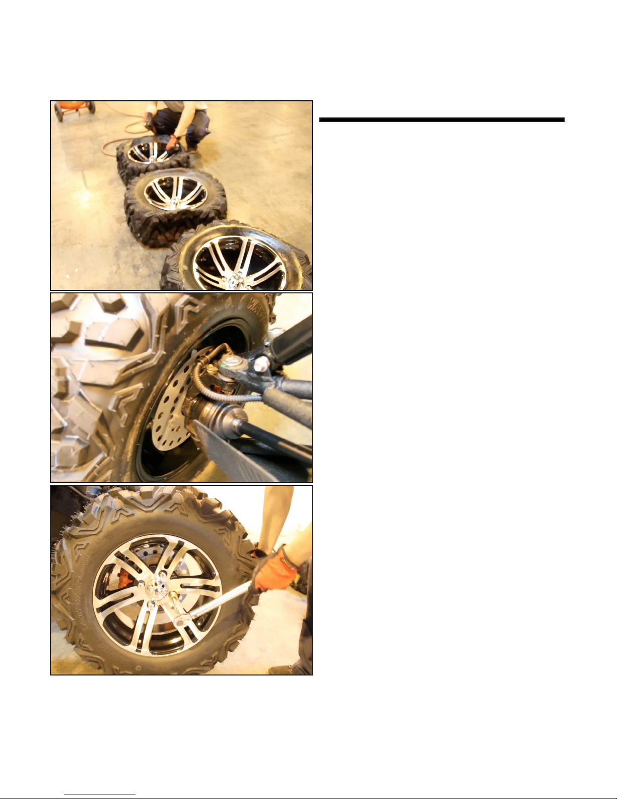
Once your UTV is raised off the ground
and all the nessacary bolts are accounted
for, you can begin to put the front and rear
shocks on.
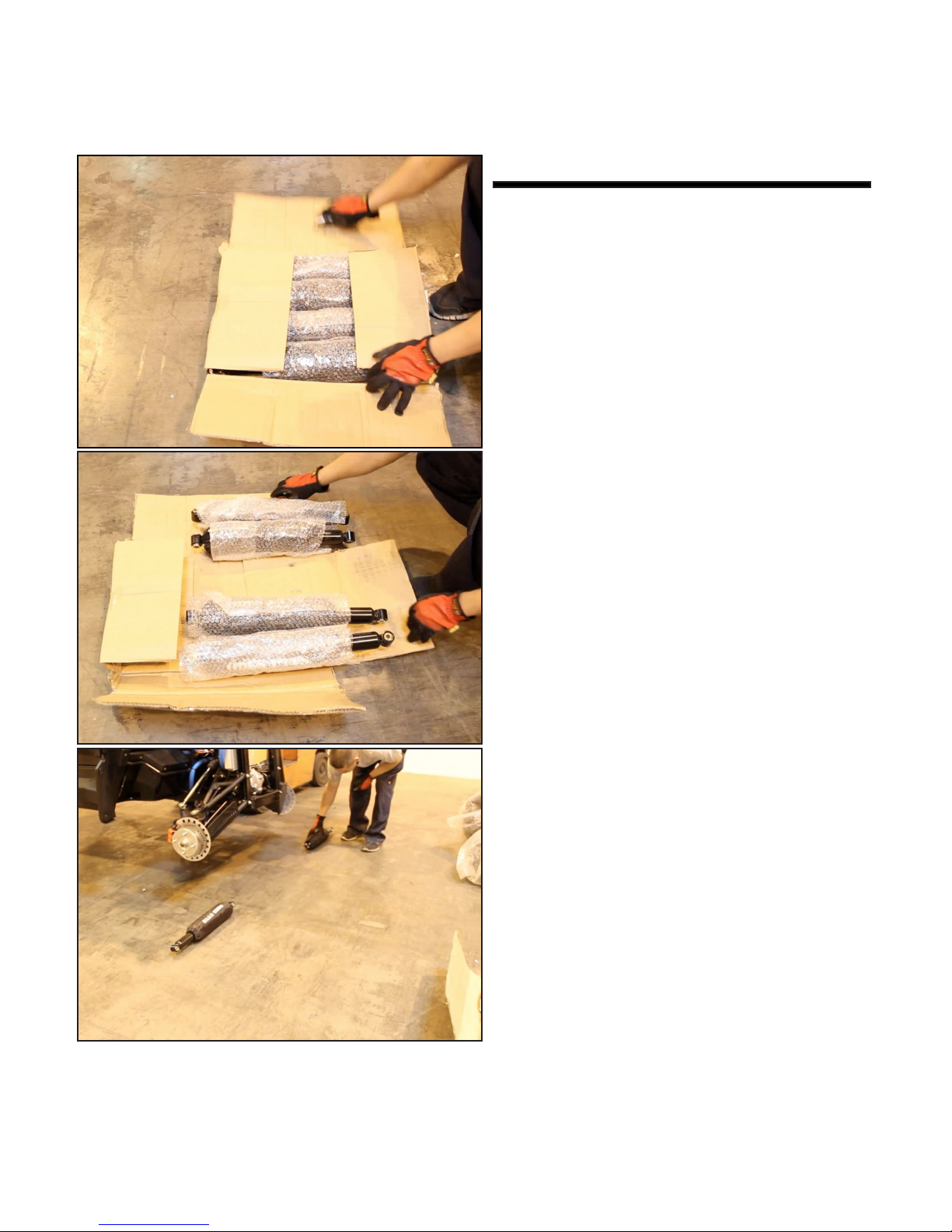
When unboxing the shocks it is impor-
tant that you immediately identify which
shocks are the rear and front to pair them
accordingly.
Once you have the shocks paired with
their partner, we suggest laying the front
shocks down by the front hubs and rear
shocks down by the rear hubs.

Shocks 1-2
Once all of your shocks are in place you
can begin to place the shocks in the arms
and bolt them down.
Remember to bolt both the top and bottom
of the shocks into place.
Once you have bolted down all shocks be
sure to tighten the bolts to eliminate any
unwanted play.

Tires
Once the shocks are securely attached to
the unit, you can now begin to put on the
tires. Please make sure to inate the tires
to 15psi before bolting onto the unit.
Once you have all 4 tires bolted on, you
will need to tighten all of the bolts with a
torque wrench.

Battery Box
Once the unit is back on the ground, you
can begin attaching the battery box to the
frame.
There are 4 bolts that connect the battery
box to the frame. Two on the left side and
two on the right side, be sure to bolt all 4
bolts down and tighten them.

Front Bumper 1-1
Once the battery box is bolted down you
can now attach the front bumper to the
frame.
Make sure all holes and brackets align in
their positions.
Bolt down the two bottom holes rst to
help keep the bumper in place.

Front Bumper 1-2
From there, slowly work your way up the
bumper applying bolts where nessacary.
Once you have placed all bolts in positon,
drill all bolts into place to secure the front
bumper down.

Auxilary Tank/ Radiator Cap
Once the front bumper is in place, you can
now attach the auxilary tank and radiator
cap.
Simply line the auxilary tank up with with
the brackets shown in the image and
tighten the screws.
The same procedure applies for the radia-
tor cap.

Radiator Guard/ Shields
You can now attach the front radiator
guard, radiator shields and horn. Align the
radiator with the holes on the frame.
Align the left and right shields with the
holes on the radiator guard and bolt them
down.
On the driver side shield, be sure to bolt
down the horn on the driver side radiator
shield. Once all bolts are in place tighten
them and wire the horn.

Passenger Handlebar
Align the bar with the two holes on the
dash as seen in the image.
Make sure you push the bar all the way
through and align it with the bracket on
the other side of the dash.
Once the bar is in place and aligned as
shown in the image, you can begin bolt-
ing down the bar on both the left and right
side. Be sure to tighten all 4 bolts.

Hood 1-1
You can now begin attaching the hood.
First place all of the hood clips on the
provided holes located on the top of the
dashboard. The holes run across the en-
tire UTV. Be sure to not miss or skip any
of the hood clips, these clips help make
the screw secure once the hood is in
place.
Once all clips are inserted you can now
place the hood on the unit. Make sure all
holes line up.

Hood 1-2
Once the hood is aligned start off by se-
curing the driver and passenger sides of
the hood.
Once the driver and passenger sides are
secure you can begin making your way
across the entire hood. Be sure to not ac-
cidently miss or skip over any holes.
Once the top of the hood is secure you
will also need to secure the area in which
the hood cover will lay. Refer to the image
for location.

Front Fender Flares
Place the clips in the area in which the
front fender ares will go.
Once all 4 clips are in place, you can
begin to secure the fender are onto the
unit.
It is easy to forget the front screw under-
neath the fender are, please be secure to
double check and secure this one as well.

Front Winch 1-1
Place the winch bracket on the front bum-
per and align it with the holes provided.
You can then place the winch on top of the
bracket and wire the winch.
Once the winch is in place you can secure
the bracket down.
Once the winch is secure, you can now at-
tach the front winch plate.

Front Winch 1-2
Clip the hook onto the winch wire as
shown in the image.
Tighten all bolts completely securing the
winch in place.
Attach the stopper to the winch wire, test
whether your winch is operational or not
and pull the wire back in.

Rear Hitch
Push the hitch into the hitch bracket pro-
vided in the rear.
Make sure the holes on the hitch are
aligned with the holes on the hitch bracket
Secure the hitch with the clip.
Table of contents
Other ODES UTVS Offroad Vehicle manuals
Popular Offroad Vehicle manuals by other brands

Gravely
Gravely Atlas JSV 3000 EFI Owner's/operator's manual

Yamaha
Yamaha BANSHEE YFZ350N owner's manual

Polaris
Polaris 550 INDY 144 owner's manual

TRX
TRX FOURTRAX RANCHER 2019 owner's manual

Polaris
Polaris 2003 Scrambler 50 Service manual

Polaris
Polaris SNOWMOBILE 2001 Owner's safety and maintenance manual