OfiTE 170-181 User manual

HTHP Filter Press with Threaded Cells
for Drilling Fluids Testing
#170-181: 115 Volt
#170-181-1: 230 Volt
Instruction Manual
Updated 6/13/2019
Ver. 4
OFI Testing Equipment, Inc.
11302 Steeplecrest Dr. · Houston, Texas · 77065 · U.S.A.
Tele: 832.320.7300 · Fax: 713.880.9886 · www.ote.com
©Copyright OFITE 2014

OFITE, 11302 Steeplecrest Dr., Houston, TX 77065 USA / Tel: 832-320-7300 / Fax: 713-880-9886 / www.ote.com 1
Intro..................................................................................................2
Specications .................................................................................3
Components ...................................................................................4
Safety...............................................................................................9
Quick Start ....................................................................................16
Operation.......................................................................................19
Data................................................................................................26
Cell Cap Assembly .......................................................................27
Maintenance..................................................................................28
Diagram .........................................................................................32
Test Cell ....................................................................................32
Warranty and Return Policy ........................................................33
Table of
Contents

OFITE, 11302 Steeplecrest Dr., Houston, TX 77065 USA / Tel: 832-320-7300 / Fax: 713-880-9886 / www.ote.com 2
Intro The OFI Testing Equipment (OFITE) High Temperature High Pressure
(HTHP) Filter Press is designed to evaluate the ltration characteristics of
drilling uids, cement slurries, fracturing uids, and completion uids under
elevated temperatures and pressures. Evaluating uids under HTHP condi-
tions similar to the downhole environment is of paramount importance. Fluid
properties must be monitored while under high temperatures and pressures
as ltration behavior and wall cake building characteristics of permeable
formations change with changing environments. These characteristics are
affected by the shape, type, and quantities of solids present in the uid and
their physical and electro-chemical interactions, all of which are affected by
changing temperatures and pressures.
OFITE manufactures and provides HTHP ltration units in two basic sizes,
175 mL and 500 mL capacities. Both are used extensively throughout the
world and in all environments, but in general the 175 mL units are designed
for eld portability, while the larger 500 mL units are designed for laboratory
usage at higher temperatures and pressures. All OFITE Filtration devices fully
conform to American Petroleum Institute (API) specications.
A complete HTHP Filter Press consists of a controlled pressure source, usu-
ally Nitrogen pressurization or Carbon Dioxide bulbs for the 175 mL units.
Top and bottom pressure manifolds are provided to simulate the differential
pressures found in a down-hole environment, and to prevent evaporation
of the base uid if exceeding the boiling point of that uid. The test cells are
provided in a variety of assemblies, depending upon the type of uid tested,
the lter media, and the temperatures and pressures desired. The test cells
are encased inside a heating jacket, which is adjustable.
A variety of lter media are available, the most common being standard API
lter paper, cement screens, and ceramic lters. The ceramic lters may be
obtained to match the pore throat or permeability of the formation. Natural for-
mation lters or cores may also be used of differing pore throat / permeability
sizes. Slotted disks of varying sizes are frequently used for lost circulation
materials studies.
The 175 mL has a maximum temperature of 350°F (177°C) and the 500 mL
heating jackets are capable of reaching 400°F (204°C). However, lower
uid volumes due to uid expansion at higher temperatures, limit the 175 mL
units to a useful working temperature of 300°F (149°C). Anyone running tests
above 350°F (177°C) must substitute a complete set of o-rings after each and
every test.

OFITE, 11302 Steeplecrest Dr., Houston, TX 77065 USA / Tel: 832-320-7300 / Fax: 713-880-9886 / www.ote.com 3
Size: 7.5" × 11" × 23.5" (19.1 × 27.9 × 59.7 cm)
Weight: 27 lb. (12.3 kg)
Shipping Size: 20" × 13" × 13" (51 × 33 × 33 cm)
Shipping Weight: 33 lb (15 kg)
Maximum Temperature
(Heating Jacket): 350°F (177°C)
Maximum Temperature (Cell): 500°F (260°C)
Maximum Pressure (Cell): 5,000 psi
Maximum Pressure (Receiver): 750 psi (5.1 MPa)
Pressure Source: CO2 Bulbs
Test Cell Capacity: 175 mL
Receiver Volume: 15 mL
Heater: 400 Watt
Power Requirement: 115 VAC, 5 Amps, 50/60 Hz
230 VAC, 3 Amps, 50/60 Hz
Specications

OFITE, 11302 Steeplecrest Dr., Houston, TX 77065 USA / Tel: 832-320-7300 / Fax: 713-880-9886 / www.ote.com 4
Components Supplies:
#153-14 Graduated Cylinder, 50 mL × 1 mL
#154-10 Dual-Scale Thermometer with Dial, 5" Stem, 50° - 500°F (0° -
250°C)
#165-44-2 Anti Seize Compound, Silver, 7g Pouch
#170-19 Filter Paper, 2½" (6.35 cm), Specially Hardened for Filter
Presses, 100/Box
#170-35 Adjustable Wrench, 6"
Assemblies:
#170-04 CO2Pressurize Unit:
#143-02-10 CO2 Puncture Head Assembly
#143-02-12 Puncture Pin
#143-02-13 O-ring
#143-02-14 O-ring
#143-03 Barrel for CO2Cartridge
#170-08 Regulator
#170-20 Manifold Block
#170-32 Needle Valve, Male, ⅛" × ⅛"
#171-23-1 Safety Pin with Lanyard
#171-34 Gauge, 1,500 psi, 2" Face, ¼" NPT Bottom
#170-06 Back Pressure Receiver, 15-mL Stainless Steel Tube for CO2
#143-00 Regulator
#143-01 Gauge, 200 psi, ⅛" Bottom Connection
#143-02-10 CO2 Puncture Head Assembly
#143-02-12 Puncture Pin
#143-02-13 O-ring
#143-02-14 O-ring
#143-03 Barrel for CO2Cartridge
#143-06 Safety Bleeder Valve
#143-11 Elbow
#170-07 O-ring
#170-28 Receiver Body
#170-32 Needle Valve, Male, ⅛" × ⅛"
#171-23-1 Safety Pin with Lanyard

OFITE, 11302 Steeplecrest Dr., Houston, TX 77065 USA / Tel: 832-320-7300 / Fax: 713-880-9886 / www.ote.com 5
#170-181-S Test Cell, Stainless Steel (For Mud Testing)
#120-910-028 O-ring for Rupture Disk, Viton 75D, Qty: 1
#130-81-040 Retaining Ring, Qty: 2
#165-44-2 Anti Seize Compound, Silver, 7g Pouch, Qty: 4
#170-13-3 O-ring for Cell, Viton 75D, Qty: 4
#170-16 Valve Stem, Qty: 2
#170-17 O-ring for Valve Stem, Viton 75D, Qty: 4
#170-18 Cement Screen, Qty: 2
#170-180-020-S Cell Body, 175 mL, Qty: 1
#171-190-023 Locking Ring, Qty: 2
#171-190-027 Rupture Disk, Qty: 1
#171-190-029 Cap Wrench, Qty: 1
#171-190-032-S Cell Cap, Outlet, Cement, Qty: 1
#171-190-033-S Cell Cap, Inlet, Cement, Qty: 1
#171-190-057 O-ring for Valve Stem, Viton 90D, Qty: 4
#171-190-058 O-ring for Rupture Disk, Viton 90D, Qty: 1
#171-190-060 O-ring for Cell, Viton 90D, Qty: 4
#170-00-1 Heating Jacket, 115 Volt:
#170-01-1 Heating Jacket, 230 Volt:
#164-32 Male Connector for Power Cable (230 Volt)
#170-05 Thermostat for HTHP Filter Press 50-500
#170-10 Thermostat Pilot Light
#170-11 Heating Element, 200W, Qty: 2
#170-15 Base
#170-21 Stand
#170-30 Stainless Steel Thermostat Cover
#170-44 Rubber Foot ½", Qty: 4
#171-32 Midget Knob
#171-82 Power Cord with Male Plug, 8' (115 Volt)
Optional:
#143-05 CO2 Bulbs, 8-Gram, Package of 10, UN 1013
#152-00 Hamilton Beach Mixer, With Container
#152-01 Armature For Model 936 H.B. Mixer, 115 Volt
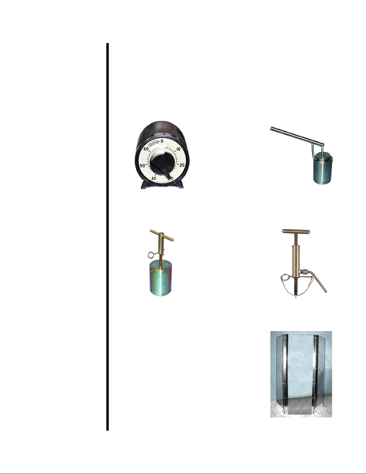
#155-20 Timer; 60 Min. Interval
#170-03 Carrying Case, Stainless Steel
#170-13 O-ring for Test Cell, NBR/Nitrile (Buna N), For temperatures up
to 250°F (121°C)
#170-13-4 O-ring for Test Cell, Peruorocarbon (FFKM), For temperatures
up to 500°F (260°C)
#170-13-5 O-ring for Test Cell, Ethylene propylene (EPM/EPDM), For tem-
peratures up to 400°F (204.4°C), Water-based uids only
#170-33 HTHP Cell Cap Puller
#170-40 Test Cell Removal and Carrying Tool
#170-91 HTHP Pressure Relief Tool
#170-92 Safety Clamp for HTHP Fluid Loss Cells

OFITE, 11302 Steeplecrest Dr., Houston, TX 77065 USA / Tel: 832-320-7300 / Fax: 713-880-9886 / www.ote.com 6
Spare parts listings are intended to be used as a reference for future pur-
chases. Everyone’s consumable requirements will be different, and replace-
ment quantities needed will depend upon the number of test performed on a
daily and/or weekly basis.
Part Number Description Qty.
#140-60-01 O-ring for Bleeder Valve 2
#143-00-1 Diaphragm for Airco Regulator 1
#143-01 Gauge, 200 psi, ⅛" Bottom Connection 1
#143-02-13 O-ring for Puncture Pin Holder 2
#143-02-14 O-ring for Puncture Pin Holder, Rear 2
#143-05 CO2 Bulbs, 8 Gram, Package of 10, UN 1013 60
#143-07 Repair Kit for Regulator (#143-00) 1
#153-14 Graduated Cylinder, 50 mL × 1 mL 2
#154-10 Dial Thermometer, 5" Stem, 50° - 500°F and 0 - 250°C 1
#170-13-3 O-ring for Cell, Viton 75D 50
#170-16 Valve Stem 4
#170-17 Valve Stem O-ring 100
#170-19 Filter Paper, 2½" (6.35 cm), Hardened for Filter Press 5
#171-190-057 O-ring for Valve Stem, Viton 90D 100
#171-190-060 O-ring for Test Cell, Viton®50
#171-23-1 Safety Pin with Lanyard 1
#170-181-SP Spare Parts Kit:

OFITE, 11302 Steeplecrest Dr., Houston, TX 77065 USA / Tel: 832-320-7300 / Fax: 713-880-9886 / www.ote.com 7
Optional Items for HTHP Filtration Testing:
The items listed below are not included in the HTHP Filter Press, but they are
items that will enable the technician to perform a more uniform and reproduc-
ible test while maintaining a high degree of safety. As optional items, the us-
age is not compulsory, but consideration should be given to these items when
running tests at elevated temperatures and pressures.
Interval Timer, 60 minute
(#155-20)
Cell Cap Removal Tool
(#170-33)
(Set Screw Cell Assemblies Only)
HTHP Pressure Relief Tool
(#170-91)
(To release trapped pressure)
Safety Shield (#171-06)
Cell Carrying Tool (#170-40)

OFITE, 11302 Steeplecrest Dr., Houston, TX 77065 USA / Tel: 832-320-7300 / Fax: 713-880-9886 / www.ote.com 8
Thermocouple Assembly
(#171-45-1)
(Direct temperature measurement
Of the uid Inside the Cell)
Stand for HTHP Cell Assembly
(#171-190-028)

OFITE, 11302 Steeplecrest Dr., Houston, TX 77065 USA / Tel: 832-320-7300 / Fax: 713-880-9886 / www.ote.com 9
Safety Pressure and Temperature Considerations
Do not use or recongure this equipment in a manner not specied in this
manual.
Pressure
There are two reasons for operating at elevated pressures when performing a
ltration analysis.
1. To test uids at temperatures above the boiling point, the vessel must
be pressurized, which in turn elevates the vapor pressure (boiling
point) so that the uid remains liquid and does not turn to steam.
2. If testing for drilling applications, pressurization will more approximate
down-hole conditions, enabling the technician to match both bottom
hole temperatures and pressures.
HTHP Filter Presses are pressurized either with Carbon Dioxide or with
Nitrogen gas. The OFITE 175 mL HTHP Filter Press, 170-00 Series, is small
enough to be portable, so it is usually pressurized with small (65 mm length)
Carbon Dioxide (CO2) bulbs, which contain 10 cm3 of CO2gas and weigh 8
grams. These bulbs are pressurized to approximately 1,000 psi and they con-
tain plenty of carrier gas to run a complete 30 minute ltration test, if running
the standard API 500 psi differential test, which is usually 600 psi on the top
manifold and 100 psi on the bottom or back pressure.
For temperatures less than 200°F (93°C) a Back Pressure Receiver is not
required as the ltrate will not reach the boiling point. However when operat-
ing above the boiling point of water, a suitable Back Pressure Receiver is
required, otherwise the test uid will turn to steam and the test is invalidated.
The standard receiver tube supplied with the 175 mL HTHP Filter Press holds
15 mL of ltrate, so it is very important that the receiver outlet ball valve is
opened after approximately ten seconds of ltrate collection, as a uid with
poor ltration qualities can easily ll the 15 mL receiver tube almost instan-
taneously. If this happens the ltrate hopefully will all be ejected from the
safety bleeder valve, but if there is too much uid volume, the liquid may end
up inside the regulator rendering it useless which will require servicing by a
knowledgeable technician.
Temperature
Normally when one experiences a loss of pressure it is not due to a failure
of the metal alloy in the cell, but rather is a failure of the o-ring or elastomer,
which provides the seal. These o-ring may deform or melt under elevated
temperatures causing a pressurization failure of the cell, which is often sud-
den and catastrophic. For example, if the valve stem o-ring suddenly fails,
then steam at 400°F and under great pressure may shoot outward horizon-
tally in one or several directions. A safety shield should always be used when
operating any HTHP Filter Press and especially when one is going to extreme
temperatures and pressures. Above 350°F (176°C) All o-rings must be re-
placed after each and every test.

OFITE, 11302 Steeplecrest Dr., Houston, TX 77065 USA / Tel: 832-320-7300 / Fax: 713-880-9886 / www.ote.com 10
Heating Jacket
Turn the thermostat knob on the front of the metal plate to change the tem-
perature of the heating jacket. The thermostat cover is marked from 1 to 10
and each whole number represents a separate temperature. Each lter press
will heat up a little differently so it is a good idea to mark with a pen directly
on the face-plate of the thermostat cover the temperature which corresponds
with each number. The actual temperature of the heating jacket is measured
with a stem thermometer and then the thermometer is placed into the cell
body.
The heating jacket will get very hot during the test so be careful not to touch
the outside of the jacket at any time during the heat-up period or the test. It is
especially easy to get burned when installing or removing the Back Pressure
Receiver as the technician is working in a very conned space. The power
cord is supplied for either 115 Volts or 230 Volts and due to the various types
of plug connectors around the world it may be necessary to change the plug
on the end of the power cord. The power cable is 8 feet in length and the
heating jacket should be placed no farther than 8 feet from the appropriate
electrical outlet. The heat up time will vary from one instrument to the next
and the pilot light will turn on when the set temperature has been reached.
The temperature of the uid inside the cell however will not be at the set tem-
perature, so always allow one hour of heating time for the uid, after the cell
has been fully inserted into the heating jacket.

OFITE, 11302 Steeplecrest Dr., Houston, TX 77065 USA / Tel: 832-320-7300 / Fax: 713-880-9886 / www.ote.com 11
The HTHP Filter Press is a very safe instrument to operate as long as the
instructions are strictly followed. It is imperative that the technician thoroughly
understands the assembly and disassembly procedures and also why the
order of steps is in place. Care should be taken to never use defective parts
and that OFITE’s temperature, pressure, and uid volume limits are strictly
adhered to at all times.
The heating jacket and cell will get very hot during the normal duration of the
test so the operator should take care to avoid burns. The operator should
be careful when attaching and removing pressure manifolds from the heat-
ing jacket, especially the Back Pressure Receiver assembly, which involves
operating in a small conned space.
Safety Retainer Pin
Always use a Safety Retainer Pin with an attached lanyard, and get in the
habit of securing the cotter pin to the pin. Improper placement of retainer pins
in the past have resulted in the pressure manifold separating from the lter
press which can cause damage to the equipment.
Retainer Pin with Lanyard 171-23-1 Safety Retainer Pin with Lanyard
Normally the 175 mL HTHP Filter Press uses CO2 bulbs, for both portability
and pressurization. Even though they are small and appear innocuous, they
can contain pressures up to 1,000 psi (6,900 kPa). CO2bulbs should never
be allowed to overheat. Exposure to re or carelessly leaving a box of bulbs
on an automobile dashboard in the sun may result in an explosion. Nitrous
Oxide (NO2) which is available in the same sized bulbs as the CO2, should
never be used as a pressure source for HTHP ltration. Under high tempera-
tures and pressures, Nitrous Oxide can detonate in the presence of grease,
oil or carbonaceous material.
CO2 Bulbs, 10/Box, (#143-05)

OFITE, 11302 Steeplecrest Dr., Houston, TX 77065 USA / Tel: 832-320-7300 / Fax: 713-880-9886 / www.ote.com 12
Working Pressure
OFITE clearly stamps the working pressure of the cell assembly along with
the assembly serial number on each cell body and cell cap. These pressure
limits should never be exceeded on the pressure manifolds and uid vol-
umes inside the cell should strictly comply with instructions (see page 20).
However, in the past HTHP cells and caps from various manufacturers were
often not stamped, or in some cases, very old cell assemblies were stamped
“2500”. Cell assemblies with set screw secured caps should never be taken
to 2,500 psi, under any temperature or condition.
O-ring Seals
Two sets of o-rings are included with the Filter Press. The rst set is made
from Viton 75D. These o-rings are black and should be used for tests up to
400°F only. The second set is made from Viton 90D. OFITE suggests that all
o-rings (cell caps, cell bodies, and valve stem) are changed each time after
running a test of 350°F (176° C) or above.
Fluid Expansion Space
Cells should never be lled completely with uid. Always leave some room for
the uid to expand under temperature. This keeps the cell caps from becom-
ing overstressed and possibly leading to a cell pressure failure or even a loss
of the cell cap completely.
Periodically check all gauges to ensure the proper pressures are in the cell,
as the pressure often increases or decreases depending upon the test proce-
dure and conditions.
API Recommended Void Space
Fluid / Temperature Void Space Fluid Volume
Water-based drilling uid. < 300°F 0.6" (1.5 cm) 138 mL
Water-based drilling uid. > 300°F 1.5" (4.0 cm) 86 mL
Oil-based drilling uid. < 350°F (176°C) 1" (2.5 cm) 115 mL
Oil-based drilling uid. > 350°F (176°C) Not Recommended-
Use 500 mL Cell
Void Space in a 1,500 psi rated cell body

OFITE, 11302 Steeplecrest Dr., Houston, TX 77065 USA / Tel: 832-320-7300 / Fax: 713-880-9886 / www.ote.com 13
Cell Corrosion
Test uids under high tempreature and pressure can corrode the cell body
and caps. Carefully inspect the cell body and calls for corrosion before and
after each test.
Some materials are more susceptible to corrosion than other. Also, some
uids and additives are more corrosive than others. OFITE offers a variety of
cell materials for different levels of corrosion resistance and cost.
Regulator Safety
The OFITE 175 mL HTHP Filter Press uses two regulators as standard equip-
ment. Both may be operated with Carbon Dioxide (CO2) or Nitrogen (N2) gas.
1. Concoa Regulator 8051140-00-1: Top or Main Pressure.
a. Maximum Inlet Pressure – 3,000 psi
b. ¼” NPT Connections
c. Single stage regulator
2. Concoa Regulator 8051179-00-1: Bottom or Back Pressure.
a. Maximum inlet pressure – 2,500 psi
b. ¼ “ NPT Connections
c. Single stage regulator
3. Never subject the regulator to inlet pressure greater than its rated inlet
pressure as shown on the regulator body.
4. Do not allow oil, oil bearing materials, grease, or other combustibles to
contaminate the inside or outside of the regulator, especially where Oxy-
gen is in use.
5. To minimize heat effects, avoid the use of piping or tubing between the
pressurized cylinder and the regulator. If unavoidable it should be as short
as practical and equipped with a shutoff valve located just before the
regulator.
6. The 8051140 regulator has been internally cleaned for Oxygen but it is
not recommended to pressurize HTHP Filtration tests with Oxygen due to
its potentially explosive nature.
7. Never pressurize a regulator that has loose or damaged parts or is in
questionable condition. Never loosen a connection or attempt to remove a
part until gas pressure has been relieved.
8. Before transporting pressurized cylinders that are not secured on a cart
designed for such transport, remove all regulators and recap the cylinders.

OFITE, 11302 Steeplecrest Dr., Houston, TX 77065 USA / Tel: 832-320-7300 / Fax: 713-880-9886 / www.ote.com 14
9. Check the regulator and all connections for leaks after installation and pe-
riodically thereafter. Also check for leaks after any service in which parts
or connections were loosened. Brush with an approved leak detection
solution and bubbles should indicate a leakage.
10. An appropriately sized pressure relief device downstream of the regulator
should be installed in your system to prevent damage to equipment and/
or injury to personnel should an internal failure of the regulator occur.
11. Do not purge oxidizing or ammable gases in the presence of ame, lit
cigarettes, or other sources of ignition or towards people.

OFITE, 11302 Steeplecrest Dr., Houston, TX 77065 USA / Tel: 832-320-7300 / Fax: 713-880-9886 / www.ote.com 15
High-Pressure
Regulator (#170-08)
Needle Valve
(#170-32)
Valve Stem (#170-16)
Heating Jacket
(#170-00-1/#170-01-1)
Cell Cap, Outlet
(#171-190-032-S)
Regulator (#143-00)
200-psi Gauge
(#143-01)
CO2 Puncture Head
Assembly (#143-02-10)
Barrel for CO2 Bulb
(#143-03)
Safety Bleeder Valve
(#143-06)
Needle Valve
(#170-32)
1,500-psi Gauge
(#171-34)
Manifold Block
(#170-20)
Safety Pin (#171-23-1)
With Lanyard
Valve Stem O-ring
(#171-190-057)
Test Cell
(#170-181-S)
Test Cell O-ring
(#171-190-060)
Valve Stem
(#170-16)
Receiver Body
(#170-28)
Support Rod
(#170-71)
Receiver O-ring
(#170-07)
(Not Shown)
Barrel for CO2 Bulb
(#143-03)
Safety Pin (#171-23-1)
With Lanyard
Cell Cap, Inlet
(#171-190-033-S)

OFITE, 11302 Steeplecrest Dr., Houston, TX 77065 USA / Tel: 832-320-7300 / Fax: 713-880-9886 / www.ote.com 16
Quick Start 1. Place the thermometer in the heating jacket.
2. Preheat the heating jacket to 10°F (6°C) above the test temperature. The
pilot light will turn on at the target temperature.
3. Inspect all o-rings. Replace any that show signs of damage or wear.
4. Apply grease to all o-rings.
5. Assemble both cell caps. Place an o-ring in the groove around the cap.
6. Make sure all threads are clean and free of debris.
7. Apply anti seize compound (#165-44-2) to the threads of the cell locking
rings and valve stems.
8. Screw the inlet cell cap into the cell and tighten it completely.
9. Screw a valve stem into the inlet cell cap and tighten it completely.
10. Pour the test uid into the cell. Leave adequate space for uid expansion.
11. Place an o-ring in the groove inside the cell.
12. Place a circle of lter paper on top of the o-ring.
13. Place an o-ring in the groove around the cell cap.
14. Screw the outlet cell cap into the cell. Tighten it completely.
15. Screw a valve stem into the outlet cell cap and tighten it completely.
16. Invert and place the cell inside the heating jacket and rotate the cell until it
is seated. Start the hour heat-up time.
17. Transfer the thermometer to the cell body.
18. Connect the Inlet (top) pressure assembly and lock it in place with the
retaining pin.
19. Connect the back pressure assembly and lock it in place with the retain-
ing pin.
20. Puncture CO2 bulbs and adjust the inlet/back pressure regulators to a
desired back pressure.
21. Open (loosen) the inlet (top) valve stem ½ turn to pressurize the cell.
22. Heat for one hour. The thermometer should register a target temperature.
The total heat up not to exceed 1 hour.

OFITE, 11302 Steeplecrest Dr., Houston, TX 77065 USA / Tel: 832-320-7300 / Fax: 713-880-9886 / www.ote.com 17
23. Increase pressure on top pressure unit to 500 psi over the back pressure.
24. Open bottom valve stem to initiate ltration.
25. Collect and note ltrate amount at 10 seconds, 1.0, 7.5, and 30.0 minutes.
a. 10 second collection is cautionary as a uid with poor ltration control
can quickly ll up the receiver.
b. If back pressure raises above 100 psi reduce the pressure by opening
the ball valve.
26. Collect ltrate for a total of 30 minutes, maintaining desired inlet and back
pressures.
27. After 30 minutes close (tighten) inlet and outlet valve stems to seal off the
cell.
28. Turn top and bottom regulator T-screws counterclockwise to release pres-
sure.
29. Open the outlet valve on the back pressure receiver to collect all the l-
trate in the graduate cylinder.
30. Open needle or bleeder valves on both the top and back pressure units.
31. Remove the top and bottom retainer pins and remove pressuring units
from cell.
32. Drain any residual ltrate collected from the top of the receiver into the
graduate cylinder.
33. Allow the cell to cool in the heating jacket.
34. Once the cell has cooled to room temperature, remove it from the heating
jacket.
35. Open (Loosen) the inlet valve stem to relieve pressure on the cell.
36. Unscrew the outlet cell cap.
37. Wash the lter cake and record the thickness to the nearest 1/3 2 ".
38. Clean and dry the lter press jacket, cell, and pressure assemblies thor-
oughly.
39. Inspect and replace any or all o-rings (All if test run > 300°F (149°C).
40. Report: Double the ltrate volume - Correct to the API standard of 7.1 in2.
Spurt Loss volume is Optional.

OFITE, 11302 Steeplecrest Dr., Houston, TX 77065 USA / Tel: 832-320-7300 / Fax: 713-880-9886 / www.ote.com 18
CO2Pressuring
Assembly
(#170-04)
Cell Assembly
(#170-12-1)
Back Pressure
Receiver (#170-06)
Valve Stem
(#170-16)
Heating Jacket
(#170-00-1 / #170-01-1)
T-Screw
Needle Valve (#170-32)
Retaining Pin (#171-23-1)
With Lanyard
Needle Valve (#170-32)
T-Screw
Retaining Pin
With Lanyard
(#171-23-1)
Relief Valve
(#143-06)
CO2 Pressuring Assembly
(#170-04)
Back Pressure Receiver
(#170-06)
Base
(#170-15)
Gauge 1500 psi
(#171-34)
Regulator
(#170-08)
Barrel for CO2 Bulb
(#143-03)
Manifold
Block
(#171-34)
Barrel for CO2 Bulb
(#143-03)
Receiver
Body
(#170-28)
Gauge 200 psi
(#143-01)
Regulator
(#143-00)

OFITE, 11302 Steeplecrest Dr., Houston, TX 77065 USA / Tel: 832-320-7300 / Fax: 713-880-9886 / www.ote.com 19
1. Plug the heating jacket into an appropriate power source. Place a ther-
mometer (#154-20) into the heating well and preheat to 10°F (6°C) above
the test temperature. A pilot light will come on when the heating jacket
reaches the temperature set by the control knob.
2. If the cell caps are not already assembled, see page 27 for assembly
instructions.
3. Inspect the cell cap and cell body. Discard any components that show
signs of corrosion, damage, or wear.
4. Inspect all o-rings. Replace any that show signs of damage or wear.
Looks for nicks, cuts, or brittle o-rings. Replace all o-rings after any test
above 350°F (176.7°C). Place a thin lm of silicone grease on all o-rings.
5. Place an o-ring (#171-190-060) on the shoulder inside the cell body on the
end marked “In”. Place another o-ring in the groove around the cell cap.
6. Make sure all threads are clean and free of debris.
7. Apply anti seize compound (#165-44-2) to the threads of the cell locking
rings and valve stems.
Operation
O-ring
Valve Stem
(#170-16) O-ringO-ring
This manual suits for next models
1
Table of contents
Other OfiTE Power Tools manuals