RGN CN70 User manual

1
Operating Manual
--CN70 Industrial Coil Nailer--
NOTE: Please read and fully understand the instructions in this
manual before operating the pneumatic power tool. Carefully read
through this OPERATOR'S MANUAL to ensure efficient, safe
operation. It is recommended that the Manual be kept readily available
as an important reference when using this tool.

2
IMPORTANT INFORMATION
WARNING: The warnings, cautions and instructions discussed in this instruction
manual cannot cover all possible conditions and situations that may occur. It
must be understood by the operator that common sense and caution are factors
which cannot be built into this product, but must be supplied by the operator.
When using the tool, basic safety precautions should always be followed to reduce the risk of
personal injury and damage to equipment.
Read and understand tool labels and operating instructions, safety precautions and warnings
in this manual before operating or maintaining this nailer.
Failure to follow warnings could result in DEATH or SERIOUS INJURY.
Most accidents that result from the operation and maintenance of nailers are caused by the
failure to observe basic safety rules or precautions. An accident can often be avoided by
recognizing a potentially hazardous situation before it occurs and by observing appropriate
safety procedures.
Basic safety precautions are outlined in the "SAFETY" section of this manual and in the
sections which contain the operation and maintenance instructions. Hazards that must be
avoided to prevent bodily injury or tool damage are identified as DANGERS or WARNINGS on
the nailer and in this manual.
Never allow the nailer to be operated by children or individuals who have not reviewed this
manual.
OPERATE THE NAILER ACCORDING TO THIS MANUAL.
WARNING!
Always follow the tool manufacturer's safety and
maintenance instructions.
Always wear safety glasses with side shields when
operating or servicing tools.
Always disconnect the air supply from the tool and empty
the magazine when servicing tools.
SAVE THIS MANUAL
FOR FUTURE REFERENCE!

3
WARNING:
The operating instructions shall draw attention to the following
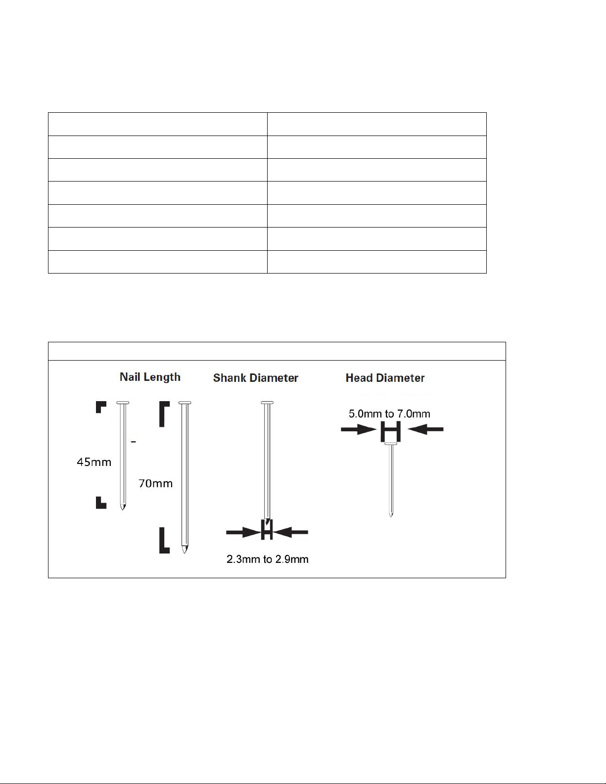
a) Only those fasteners listed in the operating instructions may be used in the fastener driving
tools;
NOTE: The fastener driving tool and the fasteners listed in the operating instructions must be
seen as one unit system in terms of technical safety.
b) Only the main energy and the lubricants listed in the operating instructions may be used;
c) Fastener driving tools marked with an inverted equilateral triangle standing on one point
may only be used with an effective safety yoke;
d) Fastener driving tools equipped with contact actuation or continuous contact actuation,
marked with the symbol “Do not use on scaffoldings, ladders”, shall not be used for specific
application for example:
when changing one driving location to another involves the use of scaffoldings, stairs, ladders,
or ladder alike constructions, e.g. roof laths, closing boxes or crates, fitting transportation
safety systems e.g. on vehicles and wagons;
e) For the maintenance of fastener driving tools, only spare parts specified by the
manufacturer or his authorized representative shall be used;
f) Repairs shall be carried out only by agents authorized by the manufacturer or by other
specialists, having due regard to the information given in the operating instructions;
NOTE: Specialists are those who, as a result of professional training or experience, have
sufficient expertise in the field of fastener driving tools and sufficient familiarity with relevant
governmental industrial protection provisions, accident prevention regulations, directives and
generally recognized technical regulations (e.g. CEN- and CENELEC-standards), to be able to
assess the safe working condition of fastener driving tools.
g) Stands for mounting the fastener driving tools to a support for example a work table, shall
be designed and constructed by the stand manufacturer, in such a way that the fastener
driving tool can be safely fixed for the intended use, thus for example avoiding damage,
distortion or displacement.
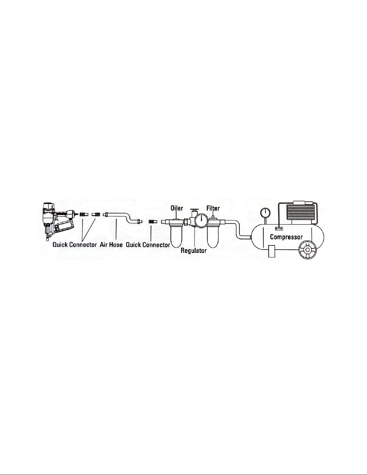
Additional instructions for fastener driving tools operated by compressed air
a) Fastener driving tools operated by compressed air shall only be connected to compressed
air lines where the maximum allowable pressure cannot be exceeded by a factor of more than
10%, which can for example be achieved by a pressure reduction valve which includes a
downstream safety valve;
b) When using fastener driving tools operated by compressed air, particular attention must be
paid to avoid exceeding the maximum allowable pressure;
c) Fastener driving tools operated by compressed air should only be operated at the lowest
pressure required for the work process at hand, in order to prevent unnecessarily high noise
levels, increased wear and resulting failures;
d) Hazards caused by fire and explosion when using oxygen or combustible gases for
operating compressed air operated fastener driving tools.

4
SAFETY INFORMATION
WARNING:
BEFORE USING THE TOOL, READ CAREFULLY AND UNDERSTAND THE
FOLLOWING SAFETY INSTRUCTIONS.FAILURE TO FOLLOW WARNING
COULD RESULT IN DEATH OR SERIOUS INJURY.
1. WEAR SAFETY GLASSES OR GOGGLES.
Danger to the eyes always exists due to the possibility of dust being blown up by the
exhausted air or of a fastener flying up due to the improper handling of the tool. For
these reasons, safety glasses or goggles shall always be worn when operating the
tool. The employer and/or user must ensure that proper eye protection is worn. The employer
is responsible to enforce the use of eye protection equipmentby the tool operator and all other
personnel in the work area. NOTE: Non-side shielded spectacles and face shields alone do not
provide adequate protection.
2. EAR PROTECTION MAY BE REQUIRED IN SOME ENVIRONMENTS.
As the working condition may include exposure to high noise levels which can lead
to hearing damage, the employer and user should ensure that any necessary
hearing protection is provided and used by the operator and others in the work area.
3. DO NOT USE ANY POWER SOURCE EXCEPT AN AIR COMPRESSOR.
The tool is designed to operate on compressed air. Do not operate the tool on any
other high pressure gas, combustible gases (e.g. Oxygen, acetylene, etc.) since
there is the danger of an explosion. For this reason, absolutely so not use anything
other than an air compressor to operate the tool.
4. OPERATE WITHIN THE PROPER AIR PRESSURE RANGE.
The tool is designed to operate within an air pressure range of 70 psi
to100 psi (5 to 7 bar). The pressure should be adjusted to the type of the
work being fastened. The tool shall never be operated when the operating
pressure exceeds 120 psi. (8.3 bar).
5. DO NOT OPERATE THE TOOL NEAR A FLAMMABLE SUBSTANCE.
Never operate the tool near a flammable substance (e.g., thinner, gasoline, etc.).
Volatile fumes from these substances could be drawn into the compressor and
compressed together with the air and this could result in an explosion.

5
6. DO NOT USE A WRONG FITTING.
The connector on the tool must not hold pressure when air supply is disconnected. If a wrong
fitting is used, the tool can remain charged with air after disconnecting and thus will be able to
drive a fastener even after the line of air is disconnected, possibly causing injury.
7. DISCONNECT THE AIR SUPPLY AND EMPTY THE MAGAZINE WHEN THE TOOL IS
NOT IN USE.
Always disconnect the air supply from the tool and empty the magazine when operation has
been completed or suspended, when unattended, moving to a different work area, adjusting,
disassembling, or repairing the tool, and when clearing a jammed fastener.
8. INSPECT SCREW TIGHTNESS.
Loose or improperly installed screws or bolts cause accidents and tool damage when the tool
is put into operation. Inspect to confirm that all screws and bolts are tight and properly installed
prior to operating the tool.
9. DO NOT TOUCH THE TRIGGER UNLESS YOUR INTEND TO DRIVER A FASTENER.
Whenever the air supply is connected to the tool, never touch the trigger unless you intend to
drive a fastener into the work. It is dangerous to walk around carrying the tool with the trigger
pulled, and this and similar actions should be avoided.
10. NEVER POINT THE DISCHARGE OUTLET TOWARD YOURSELF AND PERSONNEL.
If the discharge outlet is pointed toward people, serious accidents may be caused when
misfiring. Be sure the discharge outlet is not pointed toward people when connecting and
disconnecting the hose. Loading and not loading the fasteners or similar operations.
11. USE SPECIFIED FASTENERS.
The use of fasteners other than specified fasteners will cause the tool malfunction. Be sure to
use only specified fasteners when operating the tool.
12. PLACE THE DISCHARGE OUTLET TO THE WORK PROPERLY.
Failure to place the discharge outlet of the nose in a proper manner can result in a fastener
flying up and is extremely dangerous.
13. KEEP HANDS AND BODY AWAY FROM THE DISCHARGE OUTLET
When loading and using the tool, never place a hand or any part of body in fastener discharge
area of the tool. It is very dangerous to hit the hands or body by mistake.

6
14. DO NOT DRIVE FASTENERS CLOSE TO THE EDGE AND CORNER OF THE WORK
AND THIN MATERIAL
The work piece is likely to split and the fastener could fly and hit someone.
15. DO NOT DRIVE FASTENERS ON THE TOP OF OTHER FASTENERS.
Driving fasteners of the top of other fasteners may cause deflection fasteners which could
cause injury.
16. REMOVING THE FASTENERS AFTER COMPLETING OPERATION
If fasteners are left in the magazine after the completion of operation, there is the danger of a
serious accident occurring prior to the resumption of operation, should the tool be handled
carelessly, or when connecting the air removes all fitting. For this reason, always move the
fasteners away which remaining in the magazine after completion of the operation.
17. CHECK OPERATION OF THE CONTACT TRIP MECHANISM FREQUENTLY IN CASE
OF USING A CONTACT TRIP TYPE TOOL
Do not use the tool if the trip is not working correctly as accidental driving of a fastener may
result. Do not interfere with the proper operation of the contact trip mechanism.
18. WHEN USING THE TOOL OUTSIDE OR ELEVATED PLACE.
When fastening roofs or similar slanted surface, start fastening at the lower part and gradually
work your way up. Fastening backward is dangerous as you may lose your foot place. Secure
the hose at a point close to the area you are going to driver fasteners. Accidents may be
caused due to the hose being pulled inadvertently or getting caught.
19. NEVER USE THE TOOL IF ANY PORTION OF THE TOOL CONTROLS (e.g., TRIGGER,
CONTACT ARM) IS INOPERABLE DISCONNECTED, ALTERED OR NOT WORKING
PROPERLY.
20. NEVER ACTUATE THE TOOL INTO FREE SPACE.
This will avoid any hazard caused by free flying fasteners and excessive strain of the tool.
21. ALWAYS ASSUME THAT THE TOOL CONTAINS FASTENERS.
22. DO NOT USE ON SCAFFOLDINGS LADDERS.
The tool shall not be used for specific application for example:
When changing one driving location to another involves the use of
scaffoldings, stairs, ladders, or
Ladder alike constructions, e.g. roof laths,
Closing boxes or crates,
Fitting transportation safety systems e.g. on vehicles and wagons.

7
TECHNICAL DATA
Type of tool
CN70 Industrial Coil Nailer
Dimensions
315mmX128mmX306mm
Weight (without fasteners)
3.67kgs
Actuation mode
Contact actuation
Magazine capacity
225-300 nails
Maximum allowable pressure
8.3 bar (120psi)
Recommended pressure range
5 bar to 7 bar (70psi to 100psi)
Fasteners
Only the nail sizes shown in the table below can be driven with this nailer.
15°Wire welded coil nails
Applications
Making pallets, drums and export wooden boxes;
Crating;
Making wooden fence;
General construction applications.

8
NAILER CONNECTION AND OPERATION
NOTE: The information contained in this manual is designed to assist you in the safe operation
of the nailer. Some illustrations in this Manual may show details or attachments that are
different from those on your nailer.
Air Supply, Connections and Operating Pressure
Read section titled SAFETY. Make sure of the following before operation: Air Supply
Power Source (Compressor)
Use only clean, dry, regulated compressed air as a power source for this nailer.
NEVER use oxygen or other bottled gases, as an explosion may occur.
Use suitable air compressors used to supply compressed air to this nailer
Moisture or oil in the air compressor may accelerate wear and corrosion in the
nailer.
Drain daily.
Connections
1. Fittings
Install a female coupler to the hose. The female coupler will connect to the quick release that
fits the tool.
2. Filter-Regulator-Lubricator
NEVER connect nailer to pressure which potentially exceeds 120psi.
Filter-regulator-lubricator units supply an optimum condition for the nailer and extend
the nailer life. These units should always be used.
Filter
The filter removes moisture and dirt mixed in compressed air.
Keep the filter clean by maintaining tool regularly.
Darin daily.
Regulator
The regulator controls the operating pressure for safe operation of the nailer.
Inspect the regulator before operation to be sure it operates properly.

9
Nailer Connection and Operation
Lubricator
The lubricator supplies and oil mist to the nailer.
Inspect the lubricator before operation to be sure the supply of lubricant is adequate.
If an inline lubricator is not used, a few drops of oil will need to be added to the nailer
inlet before each use.
3. Air Hose
Air hose must have a minimum working pressure rating of 180 psi.
Hose has a min. ID of 1/4"(ISO 7-1) and max. length of no more than 17'(5 meter).
The supply hose should contain a fitting that will provide "quick disconnecting" from the
male plug on the tool.
Operating Pressure
Recommended operating pressure range is 70 to 100 psi.
Maximum permissible operating pressure is 120 psi.
Select the operating pressure within this range for the best fastener performance. The
nail length and thickness and the hardness of the wood are factors in determining what
the pressure should be set at.
Do not exceed this recommended operating pressure.
NOTE: Dirt and water in the air supply are major causes of wear in the tool.
An air filter will help to get the best performance and minimum wear from the tool. Frequent,
but not excessive, lubrication is required for the best performance. Oil added through the air
line connection will lubricate the internal parts.
WARNING
NEVER connect nailer to pressure which potentially exceed
120psi.
DO NOT USE THE WRONG FITTING ON NAILER.
The nailer and air hose must have a hose coupler so that all
pressure is removed from the nailer when the coupler is
disconnected. The connector on the tool must not hold pressure
when the air supply is disconnected. If the wrong fitting is used,
the tool can remain charged with air after disconnecting and thus
will be able to drive a nail even after the air line is disconnected,
possibly causing injury.
DANGER
NEVER use oxygen or other bottled gases, as an
explosion may occur.

10
INSTRUCTION FOR OPERATION
1. Before operation
(1) Wear safety glasses or goggles
(2) Do not connect the air supply
(3) Inspect screw tightness
(4) Check operation of the contact arm & trigger if moving smoothly
(5) Connect the air supply
(6) Check the air-leakage.(the tool must not have the air-leakage.)
(7) Hold the tool with finger-off the trigger, then push the contact arm against the work-
pieces.(the tool must not operate.)
(8) Hold the tool with contact arm free from work-piece and pull the trigger.(the tool must not
operate.)
2. Operation
Keep hands and body away from the discharge outlet when driving the fasteners because of
dangerous of hitting the hands or body by mistake.
Nail loading
(1) Disconnect the air hose.
(2) Press LATCH (210690) to open DOOR (210360), then open MAGAZINE COVER (420800).
(3) Adjust the height of NAIL SUPPORT (321360) according to nails length.
(4) Fix the first nail in the groove on FEED PAWL (210380).
(5) Close MAGAZINE COVER (420800), close DOOR (210360).
(6) Connect the air hose.
Test operation
(1) Adjust the air pressure at 70psi. (5 bar) and connect the air supply.
(2) Without touching the trigger, depress the contact arm against the work-piece. Pull the
trigger.(the tool must fire the fastener.)
(3) With the tool off the work-piece, pull the trigger. Then depress the contact arm against the
work-piece.(the tool must fire the fastener.)
(4) Adjust the air pressure as much as the lowest possible according to the diameters and
length of fastener and the hardness of work-piece.

11
MAINTENANCE AND INSPECTION
Read the section title SAFETY.
SERVICE AND REPAIRES
All quality tools will eventually require servicing or replacement of parts due to wear from
normal use. It is recommended that these operations should be performed by a professional
technician.
NOTE: The information contained in this Manual is designed to assist you in the safe
maintenance of the nailer. Some illustrations in this Manual may show details or attachments
that are different from those on your nailer.
WARNING: Disconnect air hose and remove nails from nailer when:
Doing maintenance and inspection
Cleaning a jam
Inspecting the magazine
1. DISCONNECT AIR HOSE.
2. Clean the magazine. Remove dust which may have accumulated in the magazine.
3. Lubricate the nailer rail with nailer lubricant.
Clearing a jam
Remove a jammed nail in the following order:
1. DISCONNECT AIR HOSE.
2. Remove all nails.
3. Remove the jammed nail with a slotted head screwdriver.
4. In case of frequent jams, contact an authorized service center.
A qualified person should perform repair and maintenance
Periodic maintenance to be performed:
Check that the piston bumper is operating normally. A damaged piston bumper may
cause damages to other component parts.
Check o-rings for wear or damage. Damaged o-rings may affect overall performance.
Make sure all screws are secure. Loose screws may affect overall performance.
When repairing a tool, make sure the internal parts are clean and lubricated.
Storing
When not in use of an extended period, apply a thin coat of the lubricant to the steel
parts to avoid rust.
The nailer should be stored in a warm and dry place when not in use. Do not store the
nailer in a cold weather environment.

12
PARTS LIST-CN70
NO.
CODE
Description
NO.
CODE
Description
1
610570
BOLT M6X32
49
420170
PIN CAP (A)
2
320470
SIDE PROTECTOR
50
510320
O-RING 10X2.65
3
110130
CYLINER CAP
51
510430
O-RING 20X2.65
4
520120
GASKET
52
110110
BODY
5
410170
PISTON STOP
53
510090
O-RING 4X1.5
6
620260
COMPRESSION SPRING
54
420080
TRIGGER VALVE CAP
7
320610
RING
55
320110
TRIGGER STEM
8
510570
O-RING 41.2X3.55
56
510030
O-RING 2.5X1.4
9
510990
O-RING 55X3.1
57
620050
TRIGGER VALVE SPRING
10
421410
HEAD VALVE PISTON
58
330010
TRIGGER VALVE BUSHING
11
510970
O-RING 44X4.5
59
510240
O-RING 8.6X1.9
12
310140
PISTON
60
510180
O-RING 5.8X1.9
13
322080
DRIVER BLADE(Loctite)
61
640250
STRAIGHT PIN B3X15
14
420350
CYLINDER SEALING RING
62
420090
TRIGGER VALVE CAGE
15
310130
CYLINDER
63
510410
O-RING 18.3X2.65
16
510730
O-RING 56X2.65
64
510380
O-RING 16X1.8
17
520110
CYLINDER SEAL
65
320620
SAFETY LEVER BRACKET
18
420340
CYLINDER RING
67
640190
ROLL PIN 3X32
19
511660
O-RING 84X3.05
68
640160
ROLL PIN 3X25
20
410130
BUMPER A
69
410140
HANDLE GRIP
21
410120
BUMPER B
70
320570
TRIGGER
22
610330
NUT M6(Nylock)
71
320560
CONTACT PLATE
23
420390
GUARD COVER
72
640340
ROLL PIN 3X16
24
320600
SAFETY
73
630020
SNAP RING 52
25
620250
SAFETY SPRING
74
420110
FILTER
26
322210
STEP PIN
75
110030
END CAP
27
210170
DOOR
76
510760
O-RING 58X3.55
28
640080
ROLL PIN 3X12
78
420410
MAGAZINE COVER
29
620240
LATCH SPRING
79
420240
SPRING HOLDER (B)
30
210160
LATCH
80
320690
NAIL SUPPORT PLATE
31
420160
PIN CAP (B)
81
620290
MAGAZINE SPRING
32
210150
CHECK PAWL
82
420440
MAGAZINE POST
33
620230
CHECK PAWL SPRING
83
510210
O-RING 6.3X1.8
34
610300
BOLT M8X25 (Loctite)
85
320260
MAGAZINE PIN
35
210140
NOSE
86
420430
MAGAZINE
36
510670
O-RING 50X1.8
87
410710
PLASTIC WASHER
37
420150
PIN PLUG
88
420420
DUST COVER
38
320190
DOOR PIN
89
320670
DUST COVER WAHSER
39
640340
ROLL PIN 3X16
90
410060
RUBBER BUTTON
40
320210
FEED PAWL PIN
91
610240
BOLT M6X35
41
620280
FEED SPRING
92
630070
SPRING WASHER 6
42
210080
FEED PAWL
94
410650
RUBBER PLUG
43
320640
FEED PISTON
95
410880
STRAIGHT PIN CAP
44
620270
FEED PISTON SPRING
96
323150
STRAIGHT PIN
45
410180
FEED PISTON BUMPER
97
324520
TRIGGER SLEEVE
46
320630
FEED PISTON CAP
47
630050
SNAP RING 26
P1
D322081
DRIVER UNIT
48
610250
BOLT M6X40
P2
T420091
TRIGGER VALVE

13
TOOL SCHEMATIC-CN70

14
IMPORTER:
NOBE ApS
Bjødstrupvej 10
DK –8410 Rønde
Denmark
Tel: + 45 8615 1913
www.nobe.dk / www.rgneurope.com
--Industrial Coil Nailer CN70--
2016
Table of contents
Other RGN Power Tools manuals
Popular Power Tools manuals by other brands

Harbor Freight Tools
Harbor Freight Tools PITTSBURGH PRO 63882 Owner's manual & safety instructions

Panduit
Panduit CA-800EZ installation instructions

Jet
Jet JDP-20MF Operating instructions and parts manual

Parkside
Parkside PHLG 2000 B1 Operation and safety notes

Makita
Makita BHS630 technical information

RS
RS V9671 Instruction leaflet