OFITE, 11302 Steeplecrest Dr., Houston, TX 77065 USA / Tel: 832-320-7300 / Fax: 713-880-9886 / www.ote.com 2
The OFITE 4-Unit HTHP Filter Press Heat Jacket is designed to hold four,
175-mL HTHP test cells for simultaneous testing. Each cell has a separate
temperature controller and two pressure regulators (drive pressure and back
pressure) for independent testing.
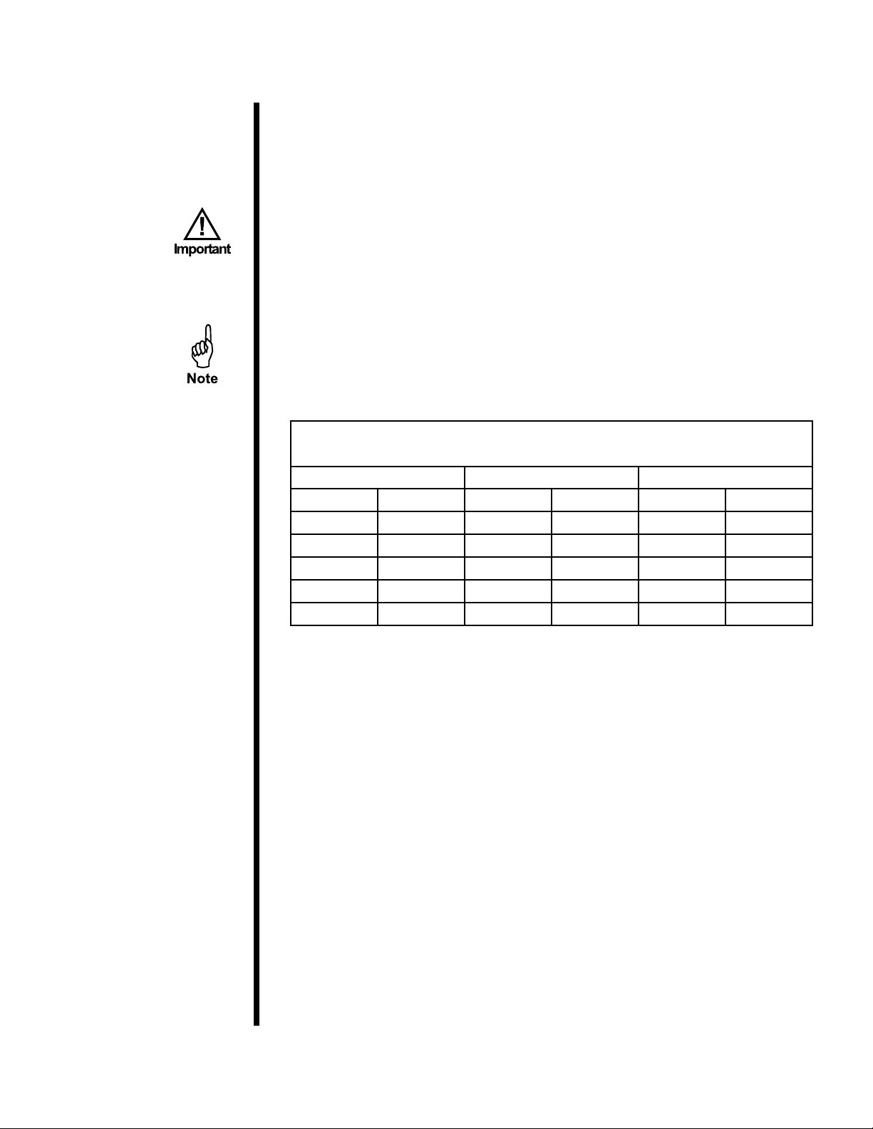
Maximum Temperature: 425°F (218.3°C)
Maximum Inlet Pressure: 2,000 PSI (13.8 MPa)
Maximum Drive Pressure: 1,350 PSI (9.3 MPa)
Maximum Back Pressure: 750 PSI (5.2 MPa)
Power Requirements: 115 VAC or 230 VAC congurations available (power
cord included)
Cell Size: 175 mL (Cells not included)
Included:
#120-05-005 Fuse Holder (230 Volt)
#120-05-005-1 Fuse Holder (115 Volt)
#120-70-1-052 Hose, Stainless Steel, 18"
#130-81-015 Relief Valve
#130-81-028 Regulator
#152-37 AC Power Cord (115 Volt)
#152-38 AC Power Cord (230 Volt)
#153-14 Graduated Cylinder, 50 mL × 1 mL, Glass
#170-06-1 Back Pressure Receiver
#170-07 O-ring for Receiver Body
#170-19 Filter Paper, Specially Hardened for Filter Presses, 2.5"
(6.35 cm) Diameter, Box of 100
#170-20 Manifold Block
#170-93 Wrench for Valve Stem
#171-45-7 Thermocouple
#171-23-1 Safety Pin with Lanyard
#174-03 Temperature Controller
Test Cells:
Test cells are not included with the instrument. The following 175 mL cells are
available.
#170-12-1 Test Cell for Filter Paper, 175 mL, Single Cap
#170-45 Test Cell with Cement Screens, 175 mL, Double Cap
#170-48 Test Cell for Ceramic Disks, 175 mL, Single Cap
#170-46 Test Cell for Ceramic Disks, 175 mL, Double Cap
Accessories:
#170-13-3 O-ring for Test Cell, Viton®/Fluorocarbon (FKM)
#170-16 Valve Stem
#170-17 O-ring for Valve Stem, Viton®/Fluorocarbon (FKM)
#170-26-1 Locking Screw, Hardened Alloy Steel
Intro
Specications
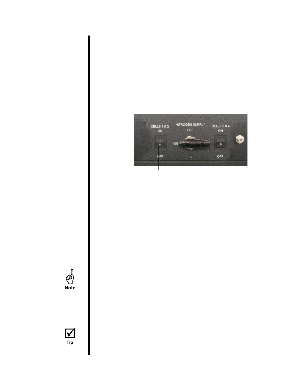
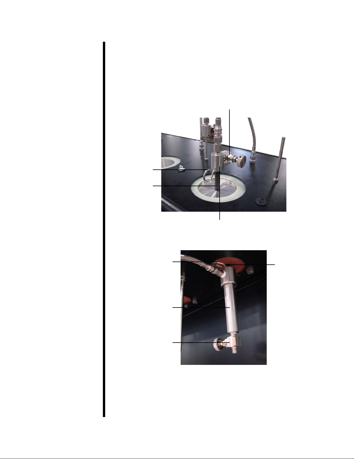
Components