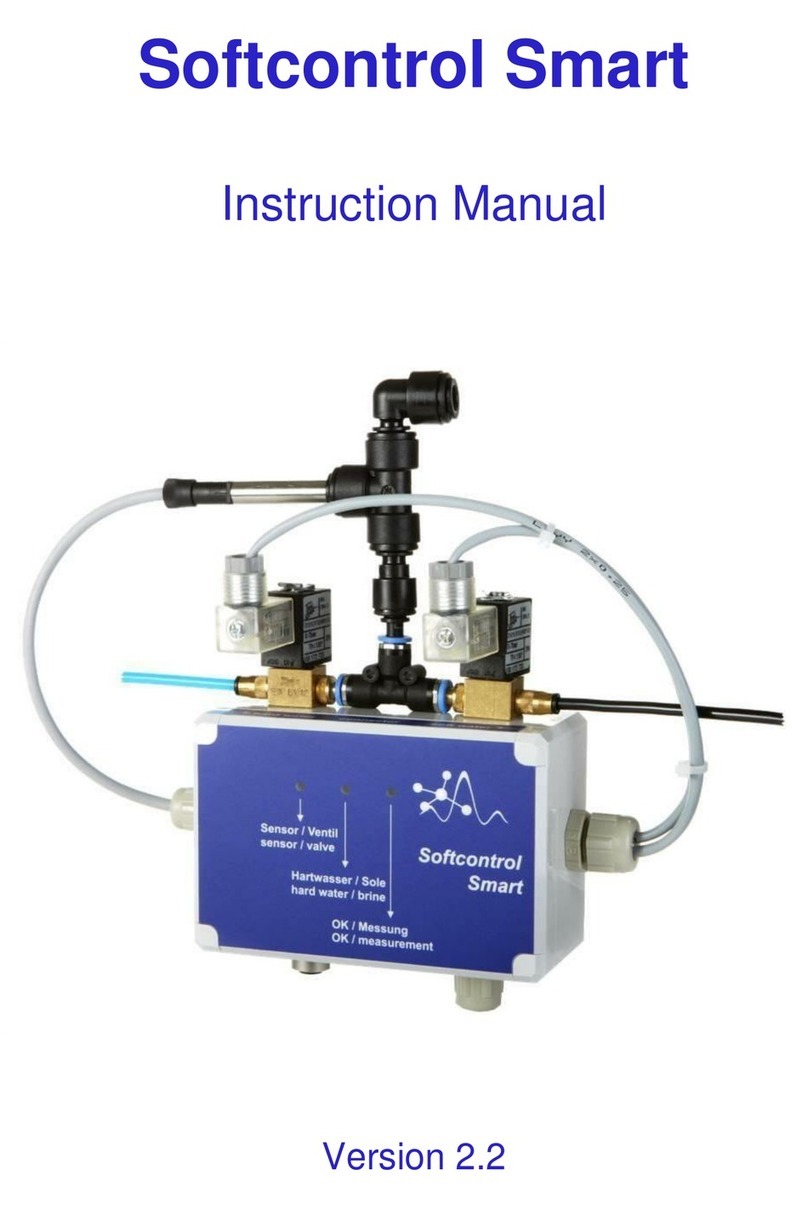
Ofs Softcontrol Data/F User manual

Softcontrol Data/F
Manual
version 2.0


3
Contents
1. Manufacturer................................................................................................................5
2. Intended use .................................................................................................................5
3. Warranty.......................................................................................................................6
4. Liability........................................................................................................................6
5. Terms of a license ........................................................................................................6
6. Safety instructions........................................................................................................7
6.1. Symbols........................................................................................................................7
6.2. Operating personnel.....................................................................................................7
6.3. Safety instructions........................................................................................................7
7. General overview of functions.....................................................................................9
8. Operating mode..........................................................................................................11
8.1. Time-controlled measurement and offline function...................................................11
8.2. Water meter or release controlled measurement and offline function.......................11
9. Installation..................................................................................................................12
9.1. Mechanical installation ..............................................................................................12
9.2. Hydraulic installation.................................................................................................13
9.3. Electrical installation..................................................................................................14
9.3.1. Terminal assignment Softcontrol Data/F...................................................................15
9.3.2. Overview of electrical connections............................................................................16
10. Commissioning ..........................................................................................................19
10.1. Requirements for commissioning ..............................................................................19
10.2. Switch on the device ..................................................................................................19
10.3. Control unit and display in measuring mode .............................................................20
10.4. Parameterization.........................................................................................................25
10.4.1. Password entry...........................................................................................................25
10.4.2. Parameters and settings..............................................................................................26
10.5. LAN interface ............................................................................................................29
10.5.1. Setting the network address .......................................................................................29
10.5.2. Control functions........................................................................................................30
10.5.3. Examples of data communication..............................................................................31
11. Service........................................................................................................................33
11.1. Calibration..................................................................................................................33
11.2. Test 4 .. 20 mA...........................................................................................................33
11.3. Test sensor contact.....................................................................................................34
11.4. Test external signaling ...............................................................................................34
11.5. Sensor - installation / exchange / storage / conditions of use ....................................34
11.6. Reset to factory settingückstellung auf Werkseinstellung.........................................36
12. Overview external alarms ..........................................................................................37
12.1. Limit value alarm active ............................................................................................37
12.2. Service alarm active...................................................................................................37
13. USB stick ...................................................................................................................39
13.1. Explanation electronical operations diary..................................................................39
13.2. USB error...................................................................................................................39
14. Software update..........................................................................................................40
15. Device accessories .....................................................................................................43
16. Technical data ............................................................................................................44
17. EU –Declaration of conformity.................................................................................45

4

5
1. Manufacturer
OFS Online Fluid Sensoric GmbH
Gesellschaft für analytische und meßtechnische Systeme
Heidelbergweg 9
07580 Ronneburg
Germany
Phone: +49 36602 51 24-0
Fax: +49 36602 51 24-29
www.water-monitoring.com/en/
2. Intended use
Softcontrol Data/F is an online water hardness measuring system for monitoring the residual
hardness at the outlet of a water softening system based on cation exchangers.
If the softener system is operated in such a way that two softener columns are temporarily
connected in series, then only the first softener column must be monitored. Monitoring of the
second softener column when connected in series is not permitted.
Characteristics
Monitoring of the soft water hardness
Option to parameterize the language: German and English
Possibility to parameterize the units of measurement: °dH, ppm, mmol / l or °f
Possibility of parameterizing the soft water limit value on the device in the range of:
o0.05 °dH ... 1.0 °dH
o1 ppm ... 18 ppm
ommol / l ... 0.18 mmol / l
o0.1 °f ... 1.8 °f
Simple, menu-driven parameterization and representation with an illuminated display
Electronic documentation on USB stick
Measured value output via 4… 20 mA interface
Automatic self-monitoring with signaling in the event of service
TCP/IP interface: parameterization and control of the device function

6
3. Warranty
The manufacturer guarantees the device for 2 years from delivery.
The ion-selective sensor is an exception.
The guarantee expires if:
Improper commissioning or improper operation or maintenance
Improper or unauthorized intervention in the devices or components
Improper analytical, mechanical or electrical influence of any kind
Damage or consequential damage caused by improper use or operation
Damage or consequential damage caused by faulty or improperly or unauthorized sys-
tems connected in the control or regulating circuit
Damage or consequential damage that can be traced back to poor quality sample liquids
4. Liability
The manufacturer assumes no liability for upstream or downstream equipment and process /
production processes of the user, their malfunctions, failures or damage or consequential da-
mage that are directly or indirectly connected to the monitoring or control circuit of the device
or that have or could have effects which can be traced back to malfunctions or malfunctions in
the manufacturer's devices.
The exclusion of liability is based on the fact that inorganic or organic precipitates, sedimenta-
tions of corrosive or oxidizing substances, microbiological contamination, flocculation or
putrefaction in the sample liquids occur only briefly and can be ignored by the user.
5. Terms of a license
With the purchase of the device, the user receives an exclusive, non-transferable right to use
the software installed by the manufacturer. Use is only approved for operating the device purch-
ased. Illegal use, distribution, copying or recompilation of the software is prohibited. The same
conditions apply to purchased software updates.

7
6. Safety instructions
6.1. Symbols
Important notes in these operating instructions are highlighted by the following symbols. In the
interests of safe and risk-free use of the device, these instructions must be particularly observed.
Attention! Failure to comply with instructions marked in this way can result in
damage to the device or the sensors.
Warning! If notices marked in this way are ignored, this can lead to injuries or
material damage.
Electric current hazard! Notes marked in this way must be observed. Failure
to do so can result in damage to the device, personal injury or property damage.
6.2. Operating personnel
The device installation and operation of the device may only be carried out by trained and qua-
lified persons. They must have read and understood the operating instructions. The following
safety instructions must be strictly observed.
6.3. Safety instructions
Softcontrol Data/F is to be installed as a wall device in accordance with the in-
stallation regulations. Operation is only permitted in rooms with a relative humi-
dity of 20% to 60% and ambient temperatures of 5 °C to 50 °C. It must be en-
sured that no condensation can form in the housing.
Operation in connection with ionization or electrolysis systems is not permitted.
The device must be protected from direct exposure to moisture and unauthorized
mechanical or electrical interference.
As portable electrical equipment, the electrical protective measure of the device
must be tested repeatedly within 24 months in accordance with DIN VDE 0702,
Part 1, the test must be verified and protection class I must be restored if neces-
sary.
Softcontrol Data/F has protection class I and may only be operated with a mains
voltage of 100… 240 volts / 50… 60 Hz with permanently effective protective
earth via an easily accessible protective contact socket. The safety plug of the
device must always be used to disconnect from the mains.
Mechanical commissioning must always be carried out in a voltage-free state.
The electrical connection to external signaling devices must not exceed the per-
missible operating voltage.

8
The raw and soft water of the softening process to be monitored must basically meet
the requirements of the applicable drinking water ordinance.
A constant sample pressure of a minimum of 1 to a maximum of 10 bar of raw and
soft water must be ensured during operation. The difference between raw and soft
water pressure should be as small as possible.
The sample liquids must be free of particles, otherwise flow filters ≤ 0.1 mm must be
installed in front of the sample inputs.
Before removing the sensor from the measuring chamber, the power supply to the
device must be interrupted. Otherwise water may splash out of the measuring cham-
ber.
There is constant water pressure up to the solenoid valves. Before servicing the sol-
enoid valves or before dismantling the measuring device, the raw and soft water lines
must be shut off. Otherwise water may splash.
When decommissioning, the sensor must be removed from the measuring cell and,
as provided by the manufacturer, stored in the original packaging in a moist, tight
and dark place.
The manufacturer reserves the right to make changes in line with technical progress.

9
7. General overview of functions
Softcontrol Data/F takes soft water in the bypass at the outlet of a water softener, depending on
the process, determines it and evaluates the residual hardness at the specified limit value. The
measurements are carried out with a selective sensor for calcium and magnesium ions, which
is inserted pressure-proof into a flow measuring chamber.
Upstream shut-off valves regulate the extraction of minimal process water quantities and the
subsequent pressure-free drainage of the water sample. Additional reagents and consumables
are not required.
The measuring system calibrates itself through cyclical automatic switchover from soft water
to raw water.
V
inlet
raw water
filter
filter
softener
soft water
raw water
inlet
raw water
pressure-
free drain
Output: external service request
Output: limit value alarm
Output: current loop 4..20 mA
Input: water meter
Input: enable measurement
Input: offline
Input: external alarm - SALIS
Mains connection
230V / 50 Hz

10
The device is parameterized with four buttons on the control unit. Device status, measurement
functions and results are shown with a display and colored LEDs. In addition, the measured
values are available via a 4… 20 mA interface.
Softcontrol Data/F monitors the soft water quality. When the hardness limit is reached, a limit
value alarm is triggered. Sensor faults are signaled externally via a potential-free contact. All
measured values and operating data can be saved on an USB stick.
Softcontrol Data/F can be connected to a LAN via an Ethernet interface. The parameterization
and control of the device function is possible via the Ethernet interface.
Softcontrol Data/F has various measurement modes and can therefore be flexibly adapted to the
respective measurement task. The measurement modes are explained below.
In the following illustration, a water softener is monitored by means of release contact-control-
led measurement with high soft water throughputs.
0,0
5,0
10,0
15,0
20,0
25,0
11.12 11.12 12.12 12.12 13.12 13.12 14.12 14.12 15.12 15.12 16.12
Water hardness in ppm
Continuous monitoring of water hardness on a softener

11
8. Operating mode
8.1. Time-controlled measurement and offline function
Assuming that the measurement pause has not been set to 0 minutes in the "interval" parameter
menu, a (steady) measurement is carried out at the interval of the parameterized measurement
pause.
The measuring process begins after switching on the device by measuring the raw water hard-
ness. The soft water measurements follow until the measured value of the sensor has stabilized
(steady measurement). Further hardness measurements are carried out according to the para-
meterized measurement pause between two hardness measurements.
If the set hardness limit is exceeded, a counter measurement is carried out in the raw water to
check. If the set hardness limit is exceeded, a limit alarm is triggered. The corresponding relay
output is switched after the set alarm delay has elapsed.
If the result of one of the following hardness measurements falls below the hardness limit value,
the limit value alarm is automatically reset. The measurements are then continued continuously
until the limit value has been undershot.
The device can be switched to offline mode via a potential-free contact (offline contact). No
hardness measurements are made in this state.
8.2. Water meter or release controlled measurement and offline function
Provided that the measurement pause has been set to 0 minutes in the parameter menu "inter-
val", the soft water measurements are carried out as long as a flow is detected.
The flow is recognized and evaluated by the impulses of an externally connected contact water
meter. Alternatively, instead of a contact water meter, an external potential-free closer (release
contact) can be used for continuous measurement.
To activate this mode, set the interval to 0 minutes and connect an external potential closer to
terminals 31 and 32. With an active short-circuit on terminals 31 and 32, the water hardness is
continuously determined. This mode works in the same way as the water meter controlled mea-
surement.
This makes it possible to enable process or flow-dependent monitoring of the soft water in the
absence of a contact water meter.
The measuring sequence is similar to the measuring sequence of the time-controlled measure-
ment. The only difference is that measurements are not time-controlled, but are triggered via a
connected potential-free contact water meter (connection terminals 27 and 28). After the mea-
sured value of the sensor has stabilized in the soft water, the device waits for further water meter
pulses. A soft water measurement takes place with each pulse.
Regardless of whether a contact water meter or a release contact is connected, the offline contact
can be used to stop the measurement as long as this contact remains closed. No hardness mea-
surements are made in this state.

12
9. Installation
9.1. Mechanical installation
Softcontrol Data/F is to be installed in the immediate vicinity of the water softening system to
be monitored as a wall unit with a mounting surface of 500 x 500 mm (width x height). For
mounting, 2 pieces M8 screws must be installed horizontally at a distance of 360 mm, prefe-
rably at eye level, in accordance with the subsurface on the intended mounting surface. The
assembly material must be provided by the customer.
It is also important to ensure that there is an easily accessible protective contact socket with a
mains connection voltage of 100… 240 V / 50… 60 Hz approx. 1 m next to the device, as well
as a pressure-free drain with nominal diameter ≥ 5/8“(DN 15) in the immediate vicinity below
the device.
For the extraction of the raw and soft water, there must be branches with preferably ¼“internal
threads at the inlet and outlet of the water softener.
It must be ensured that a water pressure of at least 1 bar to a maximum of 10 bar is constantly
applied during operation.
After selecting the mounting surface and installing the mounting screws, the device must be
hung up and screwed tight.
Overview connections
screwing 1 Drain pipe max. 2 m in length
screwing 2 Inflow of raw water (blue) and soft water (black)
screwing 3 Free for user-specific assignment (e.g. external signal line)
screwing 4 Free for user-specific assignment (e.g. external signal line)
screwing 5 Mains cable max. 1.5 m in length

13
9.2. Hydraulic installation
The hydraulic installation includes the assembly of the sample connection lines and the drainage
hose and finally the sensor:
1. Tighten the installation of the drainage hose (screw connection 1) and guide the drainage
hose into the existing drain on site
2. Screw the supplied ¼" screw-in connection into the shut-off branch of the raw water and
tightly plug the sample hose (OD 4 mm) into the screw-in connection on both sides and
into the straight plug connector (blue hose Ø 4 mm OD) pre-assembled outside the hous-
ing. To mount the prefilter, the sample hose must be disconnected at an accessible point.
3. Screw the supplied ¼" screw-in connection into the shut-off branch of the soft water and
tightly plug the sample hose (OD 4 mm) into the screw-in connection on both sides and
into the straight plug connector (black hose Ø 4 mm OD) pre-assembled outside the hous-
ing. To mount the prefilter, the sample hose must be disconnected at an accessible point.
4. Open the upstream raw and soft water branch valves and check all connectors for leaks.
The water pressure is now up to the normally closed valves raw water (RW)
and soft water (SW).
The mechanical and hydraulic installation is completed with a positive leak test.
Note:
Upstream fine filters can be omitted if the existing filter systems can exclude contamination
from dirt particles in the sampling valves!
valve soft water (SW)
valve raw water (RW)
flow
measuring
chamber
connection
drain
WW/SW RW
Abfluss/Drain

14
9.3. Electrical installation
The electrical connections relevant for the user are located on the underside of the controller
card. The measuring device is supplied with voltage via a 24 V power supply unit. The electrical
connections relevant for the user are located on the underside of the controller card.
The incoming and outgoing signal lines are connected to the terminal blocks on the underside
of the controller card in accordance with the table given in the following section. Stranded
conductors are to be provided with suitable ferrules.
USB
signals
power supply unit
24V
sensor type
630
LAN

15
9.3.1. Terminal assignment Softcontrol Data/F
The electrical connection is made according to the following table
(only connected terminals listed):
term.
assignment
comment
colour
1
GND
Supply voltage ground
brown
2
UOn
Supply voltage 24V
white
3
GND
GND –sensor
white
4
DS
Sensor
black
5
GND
GND - sensor
black
6
Sens-
Sensor
brown
8
Sens+
Sensor
blue
13
4..20mA
Measured value output 4…20mA (GND)
user
14
4..20mA
Measured value output 4…20mA (+)
user
15
Valve SW GND
GND
brown
16
Valve SW 24V
24V
white
17
Valve RW GND
GND
brown
18
Valve RW 24V
24V
white
19
Switching output 1
potential-free fault message limit value alarm
user
20
Switching output 1
potential-free fault message limit value alarm
user
21
Switching output 2
potential-free fault message
limit value (sensor) alarm
user
22
Switching output 2
potential-free fault message
limit value (sensor) alarm
user
25
Input 1 –GND
Offline –potential-free contact
user
26
Input 1 –24V
Offline –potential-free contact
user
27
Input 2 –GND
Water meter –potential-free contact
user
28
Input 2 –24V
Water meter –potential-free contact
user
29
Input 3 –GND
External alarm or SALIS sensor
–potential-free contact
user
30
Input 3 –24V
External alarm or SALIS sensor
–potential-free contact
user
31
Input 4 –GND
Enable measurement –potential-free contact
user
32
Input 4 –24V
Enable measurement –potential-free contact
user

16
9.3.2. Overview of electrical connections
USB
Display connection
service
alarm
limit value
alarm
water meter
SALIS
external alarm
offline
contact
release
measurement
4..20mA
current loop
LAN

17
External service alarm signaling via potential-free contact
Output - external request to change the sensor:
Terminals 21 and 22
The following requirements must be strictly observed for the external circuit:
Maximum connection voltage 24 volts
Maximum current flow 0,5 ampere
The following table shows the logical behavior with signal status.
signal status
contact status
Device in proper functional condition,
sensor recognized and sensor quality in the normal range
closed
Power failure or error / fault detected,
See also chapter "Overview external alarms"
open
External signaling of limit value alarms via potential-free contact
Output –limit value alarm:
Terminals 19 and 20
The following requirements must be strictly observed for the external circuit:
Maximum connection voltage 24 volts
Maximum current flow 0,5 ampere
The following table shows the logical behavior with signal status.
signal status
contact status
Soft water hardness below the set limit value
closed
Excessive soft water hardness compared to the configured limit value or
Brine entry detected after the configured alarm delay has elapsed.
See also chapter "Overview external alarms"
open

18
4 ... 20 mA current loop for measured value output
Output - measured soft water hardness: Terminals 13 (GND) and 14 (positive potential)
The soft water hardness is output linearly according to the following basic values:
4mA = 1 ppm 20mA = 10 ppm
External requirements: do not connect any external voltage, but
passive loop resistance maximum 500 OHM
Offline contact
See also chapter "Operating mode"
Output - activation of the offline mode (potential-free normally open contact):
Terminals 25 and 26
External requirements: do not connect any external voltage
potential-free external contact necessary
Release measurement
See also chapter "Operating mode"
Output - measurement release (potential-free normally open contact): Terminals 31 and 32
External requirements: do not connect any external voltage
potential-free external contact necessary
Installation water meter
See also chapter "Operating mode"
Connection - contact water meter with potential-free contact: Terminals 27 and 28
External requirements: do not connect any external voltage
potential-free external contact necessary
Connection of an external device alarm or SALIS sensor
WLAN-SALIS monitors and alerts you by email if there is a lack of salt or brine
in the water softener's salt / brine tank. Continuous maintenance work is thus
reduced to a minimum.
Link to the manual:https://t1p.de/SALIS-manual
Connection of a potential-free alarm output of an external device or the SALIS sensor:
Terminals 29 and 30
External requirements: do not connect any external voltage
potential-free external contact necessary

19
10. Commissioning
10.1. Requirements for commissioning
Before inserting the power plug into the socket outlet, the following safety instructions must be
observed:
Check electrical contacting of central control valve
Check of hydraulic tightness
Commissioning can be started after a successful check.
If “no sensor” is shown in the display, there is no electrical contact between the
sensor and the controller device.
The active operation of the device is indicated by the green "Online" LED.
A short cyclical flashing of the green LED shows that the internal control functions are active
and Softcontrol Data/F is working properly.
The specified process parameters must be set again or confirmed.
10.2. Switch on the device
After switching on the device, a quality assessment is started and completed after approx. 5
minutes. The quality assessment determines the current hardness difference between the inlet
and outlet of the water softener. As a result, a limit value violation is displayed or the soft water
quality is rated as good. The measuring program then continues to work according to the spe-
cified parameters and the result determined.

20
10.3. Control unit and display in measuring mode
Control unit
Softcontrol Data/F is parameterized via the control unit and the measurement results and ope-
rating modes are read. Parameterization and menu control are carried out using four buttons.
The measurement result and device status are shown in the illuminated display. In addition,
there are three LEDs for operating and fault signaling in the upper area:
Button functions:
4 Buttons
Display
LED display:
green LED
readiness display, flashes cyclicyally
(goes out every 5 seconds for 1 second each time)
yellow LED
-flashes measurement in raw water
red LED
-lights up alarm display device (sensor) alarm
-flashes limit value exceeding
LEDs
Activation of main menu
and confirmation after selection
Selection decreasing
Selection increasing
Leave the current menu item
without change
Table of contents
Other Ofs Water System manuals
Popular Water System manuals by other brands

RadonAway
RadonAway AIRaider 321 Instruction & installation manual

RadonAway
RadonAway HS Series Installation & operating instructions

Vetus
Vetus FTR330/13 installation instructions

Acuva
Acuva ArrowMAX HOME user manual

Armstrong
Armstrong Astro 2 Series Installation and operating instructions

Water Boss
Water Boss Series 255 Installating and operation manual