Page 4
This warranty does not cover:
Repairs necessary because of operator abuse or negligence.•
Equipment used for commercial or rental purposes.•
If this product fails due to a defect in material or workmanship within one year from the date of purchase, Ohio
Steel will at its option repair or replace it free of charge. This warranty excludes glide weldment, wear strip and
blade springs, which are expendable and become worn during normal use.
LIMITED ONE-YEAR WARRANTY
Contact Ohio Steel to arrange for product repair, or return this product to place of purchase for replacement.
When ordering repair parts always give the following information,
PRODUCT NAME, MODEL NUMBER, PART NUMBER, and PART DESCRIPTION.
This warranty gives you specific legal rights, and you may also have other rights which may vary from state to
state.This warranty applies only while this product is in use in the United States.
For missing parts or questions call 1-800-652-2321 www.ohiosteel.com
28
30
22
2
27
1
25
12
26 7
13
31
29
9
18 22 819 21
20
17
16 32 4
3
14
5
24
11
18
10
6
23
15L
21
21
20
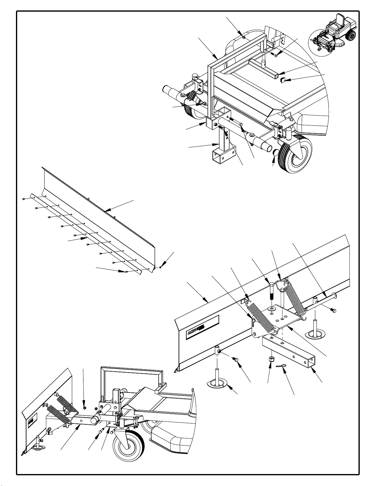
Repair Parts
20
33
21
35
34
15R
22
37
36 38
Item Num. Part Number Part Description Quantity Item Num. Part Number Part Description Quantity
1 60ZTSB-01 Snow Blade 1 20 STDBH5003500 Hex Bolt 1/2" X3-1/2" 7
2 60ZTSB-02 Pivot Plate 1 21 STDNN500 Nylock Nut 1/2" 9
3 60ZTSB-03 Support Tube 1 22 STDPH7 Hair Pin 4
4 60ZTSB-04 Adjustment Tube Weldment 1 23 STDBS5001500 Pointed Bolt 1/2" X 1-1/2" 1
5 60ZTSB-05 Rotating Lift Weld 1 24 STDBH3751750 Hex Bolt 3/8" X1-3/4" 1
6 60ZTSB-06 Side Support Bracket 2 25 STDBH313750 Hex Bolt 5/16" X3/4" 9
7 60ZTSB-07 Collar Weld 2 26 STDNC313 Lock Nut 5/16" 9
8 60ZTSB-08 Adaptor Plate (Mounting) 2 27 60ZTSB-27 Blade Spring 9-1/2" 2
9 60ZTSB-09 Support Pin 2 28 STDBH7504000 Hex Bolt 3/4" X 4" 1
10 60ZTSB-10 Foot Lift 1 29 STDNN750 Nylock Nut 3/4" 1
11 60ZTSB-11 Foot Kick Weld 1 30 60ZTSB-30 Handle Pivot Pin 1
12 60ZTSB-12 Wear Strip 1 31 STDBH5001000 Hex Bolt 1/2" X 1" 2
13 60ZTSB-13 Glide Weldment 2 32 STDBH5004000 Hex Bolt 1/2" X4" 2
14 60ZTSB-14 Blade Pivot Rod 1 33 STDFW500 Flat Washer 1/2" 4
15L 60ZTSB-15L Cadet Mounting Plate Left 2 34 60ZTSB-34 Square Cap 2
15
60ZTSB-15
Cadet Mounting Plate Right 2 35 60ZTSB-35 Rotating Lift Cap 2
16 STDBH3751000 Hex Bolt 3/8" X 1" 8 36 60ZTSB-36 Hardware Bag 1
17 STDFW375 Flat Washer 3/8" 8 37 60ZTSB-37 Decal 1
18 STDNC375 Lock Nut 3/8" 9 38 60ZTSB-38 User Guide 1