OHM BRS-12A3 User manual

Manchester - England
12” active 3 channel subwoofer
BRS-12A3
User Manual

BRS-12A3 User Manual SCD/ATT Version 1.2 29-04-2019
2
Wellington Close
Parkgate Industrial Estate
Knutsford
Cheshire
WA16 8XL
United Kingdom
Tel: +44 (0)1565 654641
Email: [email protected]
Website: www.ohm.co.uk
aural ltd

BRS-12A3 User Manual SCD/ATT Version 1.2 29-04-2019
3
Introduction .................................................................................................................................
Welcome to the Ohm family ............................................................................................
Unpacking ..........................................................................................................................
Register your product ......................................................................................................
Safety precautions ......................................................................................................................
BRS-12A3 Subwoofer .................................................................................................................
Description .........................................................................................................................
Key Features ......................................................................................................................
Rear Panel Overview .........................................................................................................
System Wiring .............................................................................................................................
Mains Wiring .....................................................................................................................
Speakon Wiring .................................................................................................................
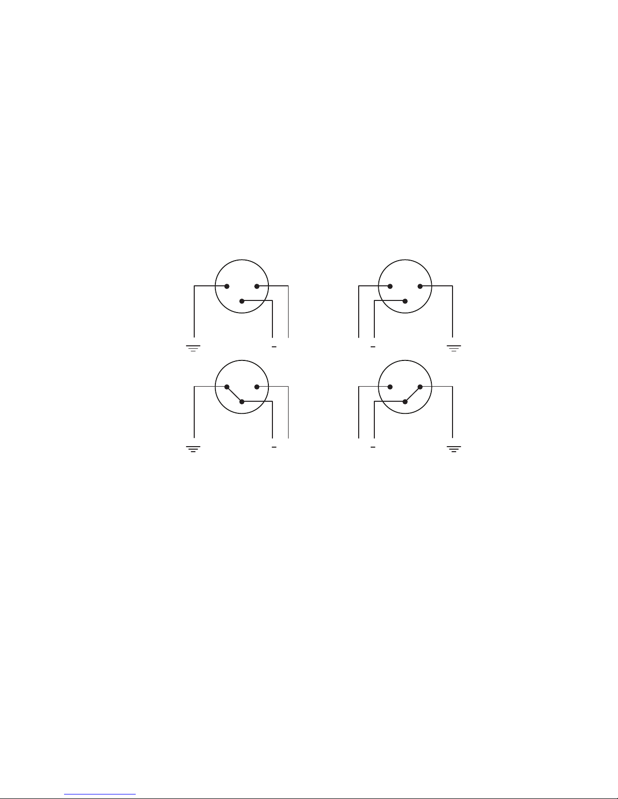
XLR Wiring ........................................................................................................................
Additional Deployment and operating precautions ................................................................
LCD Touchscreen ......................................................................................................................
LCD control Menu Overview ..........................................................................................
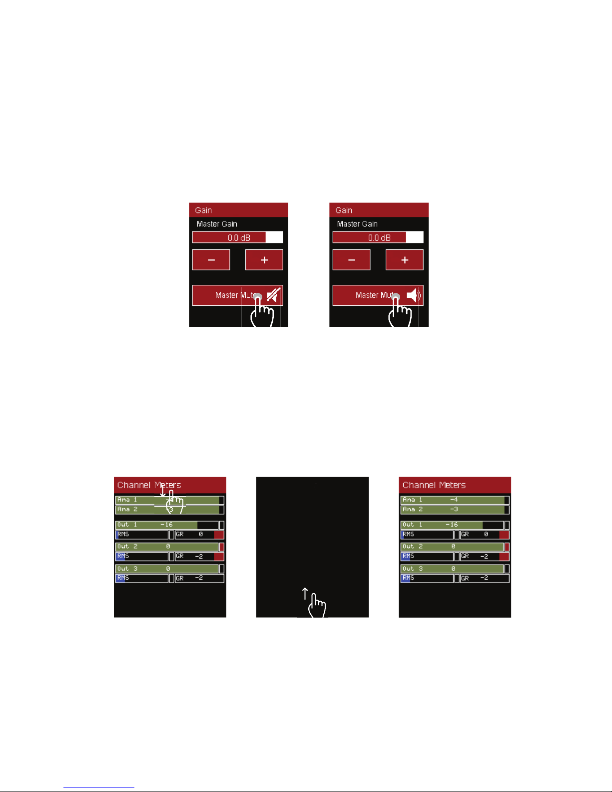
Adjustment ........................................................................................................................
Screen Off .........................................................................................................................
LCD Touchscreen Menu Tree ........................................................................................
Initial System Testing ..................................................................................................................
Pro-A-Sync ...................................................................................................................................
Download Software ..........................................................................................................
Start-up Window ................................................................................................................
Menu and Firmware Updates .......................................................................................
Controller Window ............................................................................................................
Header Menu .....................................................................................................................
Main Tab ...........................................................................................................................
Input Tabs (PEQ) ...............................................................................................................
Output Tabs (PEQ) .............................................................................................................
Technical Specification ..............................................................................................................
Dimensions and Accessories ...................................................................................................
2D Drawing and Dimensions ...........................................................................................
3D Drawing .......................................................................................................................
Accessories and Spare Parts ........................................................................................
BRSC-12 Cradle Fitting Instructions ......................................................................................
Example System Set-ups .......................................................................................................
OHM (Aural LTD) Product Warranty .........................................................................................
Troubleshooting Guide ..............................................................................................................
4
4
4
4
5
6
6
6
6
7
7
7
8
9
9
9
10
10
11
12
13
13
13
13
14
14
16
17
18
20
21
21
21
21
22
23
24
25
Contents

BRS-12A3 User Manual SCD/ATT Version 1.2 29-04-2019
4
We have spent the last 40 years perfecting building practices, honing the acoustic envelope whilst constantly
redefining what is possible in pursuit of the perfect product.
Thank you for your faith in our products and purchasing this equipment that we are proud to manufacture.
Everything we make is built with care and consideration, delivering many years of sonic excellence with industry
leading reliability.
We hope you enjoy using your new equipment.
Upon delivery, please check the carton and BRS-12A3 for damage which could have occurred in transit. If any is
found, please contact the delivery courier to start a claim. Keeping the packaging is a great way of making sure
that any future vacations the unit needs to make are as secure as possible.
This BRS-12A3 has been made with our environment in mind. There are many items used in its manufacture
which are highly recyclable when the unit has reached the end of its useful life. Please contact your local authority
to arrange responsible disposal.
Unpacking
Register your product
Welcome to the Ohm family.
Remember to register your product to take advantage of our free 1 year extension. Simply
follow the QR code to take you to our online registration portal or visit www.ohm.co.uk/
registration from any computer.
Alternately fill in the warranty form included with your product and return to us within 90
days of purchase.
We acknowledge all warranty applications by email. It’s important to keep this notification
for future reference
Introduction

BRS-12A3 User Manual SCD/ATT Version 1.2 29-04-2019
5
Safety Precautions
Read these instructions carefully to help avoid personal injury and equipment damage.
Professional loudspeaker systems can create sound pressure levels that can be dangerous to health.
Even moderate sound levels (90 dB SPL or more) can cause permanent damage to hearing if you are exposed
to it over a long period.
To help prevent injury, please refer to the following information:
• Be sure to leave enough distance between speakers and the public
• Ensure that all hardware, fixings and fasteners used for installation, mobile, hung or ground-stacked use are
of an appropriate size and load safety factor. Pay attention to all instructions and relevant safety guidance
on datasheets
• Regularly check the loudspeaker cabinets, accessories and load bearing bolts for visible signs of wear &
tear. Replace when necessary
• Read, retain and fully understand the user manual before use
• Do not install near heat sources e.g. radiators, heat registers or fires and avoid direct sunlight
• Keep away from moisture, humidity or rain. Liquid should not be stored/placed on top of the unit
• Keep all ventilation surfaces clean and un-obstructed
• This CLASS 1 product always requires an earth connection when connected to mains power
• Before powering up the system, make sure all connections have been properly made
• Ensure all wiring is safe to use and complies to your local standards
• Unplug the unit when not in use, during electrical storms or mains voltage disturbance
• To prevent shock risk, never open this product; there are no parts inside that are serviceable by the user
• Do not attempt to modify or change the unit’s operational specifications
• For service, please return the module to Ohm for appropriate care
• This product requires a mains connection to work
• If the unit works in an unintended way, disconnect from the power and contact Ohm for support
• Do not suspend the unit from its handles
• Ohm strongly recommends this product is only installed/operated by qualified professionals
• This BRS-12A3 is not designed for permanent outdoor use
Potential risk of equipment damage.
Speakers have a permanent magnetic field. Magnetic fields can cause damage to magnetic data media, Hard
disk drives and other equipment. Keep all loudspeakers at least 1m away from sensitive equipment.

BRS-12A3 User Manual SCD/ATT Version 1.2 29-04-2019
6
BRS-12A3 is a compact, active, 3 channel subwoofer system with 1 x 12” long excursion driver. Integrated Class D
amplifiers deliver 2 kW’s of output through 3 DSP channels which can be adjusted locally or remotely configured
through a Windows PC or Mac computer which has Pro A Sync software installed.
A low-profile design height of 333 mm allows for installation in confined spaces, under seating or ceiling mounted
(using optional hardware).
Designed with integrated handles and pole mounting plate for portable applications.
Key Features:
• 3 Channel amplified system with parallel subwoofer output
• Rebated Baltic Birch Plywood construction
• Universal 100 to 240 Volt mains operation (AC only)
• Integrated Class D Power modules
• Passive cooling provides silent operation and low maintenance
• Fully integrated peak and RMS limiters with active Gain Reduction
• LCD touchscreen selection and adjustment to gain, preset, phase and channel mutes
• 2 kW Amplification, 1 kW for internal bass driver & parallel Sub, 2 x 500 W for satellite loudspeakers
BRS-12A3 Subwoofer
USB (Type B)
Cooling
Fins
Output B
Channel 3 4ΩMinimum Load
Channel 1 (sub link for BRS-12-2
only)
Input A
Link A
Audio input & signal link outputs
Input B
Link B
Power link
output
NAC3MX-W
LCD
Touchscreen
Output A
Channel 2
4ΩMinimum Load
Power Input
NAC3FX-W
Rear Panel Overview
BRS-12A3
25.6 kg
000012
Description:

BRS-12A3 User Manual SCD/ATT Version 1.2 29-04-2019
7
Mains Wiring
System Wiring
The mains input and power link output are via Neutrik powerCON True1 connectors. The input connector
(NAC3FX-W) is supplied with the unit. The output link is type NAC3MX-W and available separately.
Only flexible copper wire should be used. We recommend a minimum diameter of 1.5mm per conductor but
recommend 2.5mm. Colour coding for wiring alters from one region to another. Please check and confirm your
local colour code.
Insert the phase conductor into the receptacle marked (L) and tighten the screw terminal with a T8 Torx bit.
Repeat the process with the non-phase conductor into the (N) connection and the earth wire into the (earth
symbol) connector on the trueCON plug. Refit the cable clamp and tighten the collar onto the plug chassis.
Region Phase (Live) Non-phase (Neutral) Earth
Europe, South Africa Brown Blue Green/Yellow striped
Australia, New Zealand Brown or Red Blue or Black Green/Yellow striped
Brazil Yellow or Red Blue Green
USA, Canada Black White Green/Yellow striped
Asia Red / Yellow / Blue Black Green/Yellow striped
All mains wiring should only be carried out by a competent, qualified electrician.
Speakon Wiring
Two 4-way speakON® connectors are used for connections to satellite mid-high speakers & subwoofer. Mating
connector type is NL4FC.
Wiring is as follows:
Channel B Output
1+ Phase output
1- Non-phase output
2+ Subwoofer phase output
2- Subwoofer non-phase output
Channel A Output
1+ Phase output
1- Non-phase output
Non-phase
Mid-high
phase
Positive
Mid-high
Non-phase
Subwoofer non-phase
Subwoofer phase
1+
1-
2+
2-
1+
1-
2+
2-

BRS-12A3 User Manual SCD/ATT Version 1.2 29-04-2019
8
12
3
21
3
Male
XLR
Female
XLR
+
+
Balanced XLR
Unbalanced XLR 12
3
21
3
Male
XLR
Female
XLR
+
+
XLR Wiring
XLR Input sockets are provided to connect a signal source. Output links offer the ability to daisy-chain low level
input signal to another BRS-12A3 system.
Wiring is industry standard with the following assignments:
Pin 1 Chassis/Ground
Pin 2 Phase/positive (hot) signal
Pin 3 Non-phase/negative (cold) signal
When using the system with an unbalanced input, link pins 1 & 3 together.
Do not overload the internal amplifiers by using unsuitable loads/impedances. The mid-high outputs are designed
to give maximum output at 4Ω. Ensure all cabling is in good condition with suitable connectors terminated
appropriately. Failing to consider output impedances or using poor quality/damaged cables will significantly
impact sound quality and system reliability.

BRS-12A3 User Manual SCD/ATT Version 1.2 29-04-2019
9
Safety should be the first and foremost consideration when using this system.
For stability, the BRS-12A3/BRS-12-2 should not be used on a surface with more than +/- 5° incline if satellite
speakers are being pole mounted using the threaded insert adaptor.
If the unit has been stored in a cold environment, it should be allowed to come to room temperature before
use. If condensation forms on the rear panel, ensure the unit has dried before powering the system.
Do not use this unit without an earth connection. Ensure that any input source is connected to the same
mains circuit & earth point as the BRS-12A3 to avoid mains earth hum-loops.
Cables to and from the unit should be placed in a way that does not present a trip hazard. Ensure all cabling
is free from damage and that all connectors are properly seated before powering the system. Do not site the
system close to heat sources and ensure that there is sufficient air flow to prevent overheating.
Under no circumstances should this system be used in environments with high humidity or rain. If possible,
try to site the amplifier panel out of direct sunlight to reduce thermal loading and increase LCD visibility.
Only use genuine OHM accessories with this product
In simple system set-ups, the unit can be controlled entirely via the touch-screen display. After initial power-up, the
main screen on the LCD displays the Channel Meters screen. This shows VU input and output gains, gain reduction
levels and peak/RMS limit status.
The touchscreen menus operate with swipes from the left of the screen to the
right to progress through the different pages. A finger tip dragged gently across
the bottom section of the screen works best to change screens.
Swiping scrolls through the six screens as follows:
Channel Meters >>
Gain >>
Mute & phase >>
Channel delay >>
Channel Gain >>
Preset >>
Additional Deployment and Operating Precautions
LCD Control and Menu Overview
Analogue VU Input Level Meter Channel A + B >
Channel 1 (sub) VU Output Level Meter >
Channel 2 VU Output Level Meter >
Channel 3 VU Output Level Meter >
RMS Limiter VU Meter Channel 1 > <Gain Reduction VU Meter Channel 1
RMS Limiter VU Meter Channel 2 > <Gain Reduction VU Meter Channel 2
RMS Limiter VU Meter Channel 3 > <Gain Reduction VU Meter Channel 3
*It is normal for the VU meters to fluctuate slightly when no input signal is present.
**Throughout this manual, input A & B and input 1 & 2 are used interchangeably.
LCD Touchscreen

BRS-12A3 User Manual SCD/ATT Version 1.2 29-04-2019
10
The LCD screen has a screen-off function. This can reduce rear facing glare when used in dark environments. It
can also protect the unit from unauthorised adjustments after the system has been set.
To switch screen off: Swipe from the middle top of the display to the middle of the bottom.
To turn the screen on: Swipe from the middle of the bottom of the screen to the middle of the top.
Screen Off
Item adjustment is done by lightly tapping the appropriate box displayed on-screen. Individual taps are required
to adjust items. Pressing and holding screen buttons will not give consistent results.
When a menu page has been selected, the page will time-out after 15 seconds if no user input on the LCD is
detected and return to the Channel Meters screen.
Preset selection and gain adjustment is remembered after power-off and re-applied when power is connected.
Adjustment
All function buttons (master mute, individual mutes and phase correction) behave like toggle button. Press the
button once to activate it (the icon will change to confirm the function is active), then press the button again to
turn it off (the icon will return to its normal view confirming the function is switched off).
Swipe down to turn off Swipe up to turn off

BRS-12A3 User Manual SCD/ATT Version 1.2 29-04-2019
11
Channel Delay:
Minus (-) buttons reduce
the delay on each channel
individually. The (+) plus buttons
increase the delay to each
channel.
Minimum delay is setting is 0.00
mS. Maximum delay is 10 mS
per channel.
Channel Meters:
A visual display of input and
output levels.
RMS capacity is shown in blue.
Gain reduction shown in red.
Gain reduction increases audio
compression and degrades
system performance.
Preset Selection:
To select a preset, press the
appropriate preset button. After
a short delay, the speaker icon
will move to the newly selected
preset.
Swiping up and down reveals
more presets if they are
available.
Mute and Phase:
Individual channel mutes and
phase is adjusted on this page.
Mutes buttons are shown on
left, phase buttons on the right.
When the speaker icon is on
a black backgrounds and has
a diagonal line through it is
muted.
The circle icon relates to phase.
When it is on a red background
it is phased normally. When it is
on a black background it is 180°
out of phase.
Channel Gain:
Minus (-) buttons reduce the gain
on each channel individually.
The (+) plus buttons increases
the gain to each channel.
Minimum gain is -60dB,
maximum gain is +17dB.
Best sonic performance is
realised between -60dB and
+5dB.
Master Gain & Master Mute:
System output level can be
Adjusted from here. Minimum
input = - 60dB. Maximum gain is
+20dB. Best sonic performance
is achieved between -50dB and
+5dB.
The Master mute function mutes
all channel simultaneously.
When the speaker icon has a
diagonal line through it, the
outputs are muted. Press the
button again to un-mute. The
icon will return to a speaker.
LCD Touchscreen Menu Tree

BRS-12A3 User Manual SCD/ATT Version 1.2 29-04-2019
12
After the system is fully wired and all speakers are in their final positions, apply power to the BRS-12A3 whilst
making sure that input signal is turned off.
Once the system has powered up, completed its self-test and is displaying the signal screen, gently turn the input
signal up and confirm all internal and external drivers are working as expected.
Basic individual channel adjustment to gain, mute and phase can be done via the rear LCD screen or for more in-
depth features, on any USB connected Windows or Mac computer running Ohm’s Pro-A-Sync software.
Initial System Testing

BRS-12A3 User Manual SCD/ATT Version 1.2 29-04-2019
13
This unit when connected via a USB lead to a compatible computer can run Ohm’s proprietary Pro-A-Sync software
which gives greater control over the performance and setup of the unit.
Visit www.ohm.co.uk/downloads to download the current version of Pro-A-Sync for your computer (macOS and
Windows versions are available). Once installed, power up the BRS-12A3 and connect a USB type A to B lead from
the computer to the module located on the rear of the BRS-12A3. The unit should be found and will populate the
Devices section of the menu.
Pro-A-Sync Software
Start-up Window
Download Software
1. File
Clicking file gives you the options to install speaker definitions, manage speaker definitions, install DSP
Definitions, manage DSP Definitions and create demo device from DDD (Device Definition Data file). (Not
applicable on BRS-12A3)
2. Help
Clicking Help allows you to select a demo device, and get information about the software version you are
using. (Not applicable on BRS-12A3)
3. Name
This field is used to label the unit. Click the Menu cog, then click the Device Name box and type a suitable
new name. Press enter when complete.
4. Type
Displays the Model of the unit that is selected
5. Connection
This will show the USB COM port which the unit is connected to
6. Current Preset
Select by double-clicking the box, then on the triangle, then the desired preset.
7. Input
Displays input type. This unit uses analogue input signals
8. Controller
Gain, PEQ & mute adjustments. Click this button to open a new controller window. See page 14
9. Menu
Shows device information and firmware update feature.
At the main window, click the menu cog in the menu section of the screen.
Menu and Firmware Updates
Click Device info to either change the Device Name or confirm which firmware is running on the unit.
To update the firmware on the unit, click the menu cog **. Then select Update Firmware option*. A menu box
will appear detailing what firmware is currently installed and if there is a newer version available. If there is newer
firmware available, click the Yes, to install it. An update window will show progress of the update.
Simply click on the firmware update. A box will appear which will warn that the device will be updated with the current
3 4 5 6 7 8
12
9

BRS-12A3 User Manual SCD/ATT Version 1.2 29-04-2019
14
This is used to adjust channel output gains, phases, mutes and PEQ. Select this from the main Devices window
by clicking the controller button.
Controller Window
Header Menu
1. Device Name
Name of the device connected to the software.
2. Preset selection
This option allows different presets to be recalled. Simply click the triangle on the right of the box, a drop-
down menu will appear with your presets listed. Select one by moving the highlight to your selection and
clicking on it. The preset will become active.
There are two routing blank presets to choose from.
Ain_2_3_bin_SuB. This is a mono preset, routing input A to outputs 2 and 3. Input B
is routed to the subwoofer channel 1.
A_Bin_Sub Ain_2 Bin_3, This is a stereo blank preset, Routing Input A to output 2,
Input B to output 3. The Subwoofer channel 1 is Summed from Input A and input B.
3. Preset Options
Clicking the preset cog button reveals a drop down menu for; saving current
preset, revert to the original preset, overwrite the current preset and import and
export of current presets for backup purposes.
Save new user preset - Click preset cog, click the “Save New User Preset”
option. Type the name of the new preset and press enter. This new preset is
now stored.
Revert to this preset - When alterations have been made to a preset which
you are not happy with, simply click the preset cog then select “Revert to this
preset” option. This will re-load the previously saved version of the file.
Overwrite this preset - Once settings have been adjusted, click the preset cog then click “Overwrite this
preset” to save the new adjustments to the currently recalled preset. This action cannot be undone.
Delete this user preset - Selecting this option will delete the currently recalled preset. This action cannot
be undone.
Export current preset to file - Use this option if you wish to run the current preset on another unit or make
a copy/backup of the file. Simply select “Import preset to file” option, in the new pop-up window, navigate
to the file location on your computer you wish to load, and press enter to confirm. This will store the preset
locally on the BRS-12A3.
Import preset from file - Use this option if you wish to load a previously saved preset onto this unit. Simply
select “Import preset from file” option, in the new pop-up window, type the name you wish to call the file,
and select a location to store the file. Press enter to confirm.
Manage User Presets - Use this function if you wish to delete multiple presets or change file names. Please
note that factory loaded presets (denoted by a factory symbol in the preset list) cannot be deleted. User
presets are show with a smiley face.
firmware will be re-installed. Click Yes, please reinstall. A menu box will show progress of the update.
* NEVER DISCONNECT THE POWER DURING A FIRMWARE UPDATE. This WILL permanently damage your
equipment and invalidate your warranty.
** Important note for Firmware Updates. - The computer connected to the device MUST have an active internet
connection for this feature to work.

BRS-12A3 User Manual SCD/ATT Version 1.2 29-04-2019
15
4. Input
Analog input only applicable on BRS-12A3
5. Sync Status
This shows the current connection status to the BRS-12A3.
Green shows an active connection.
Yellow shows the unit is updating settings which have been changed.
Red shows that there is no connection between the computer and BRS-12A3.
6. Master Gain
This slider adjusts all output gains simultaneously. Whilst clicking on the slider, drag to adjust gain. Clicking the
up & down arrows next to the gain number will increase the gain in 1dB increments. Double clicking the gain
number allows direct entry of a number. Hit enter to submit your adjustment in the case of direct numerical entry.
Master Mute - This button mutes all output channels simultaneously.
Click the button once to toggle the mute on.
Click again to un-mute.
7. Selection Tabs
The software is split into three screens, MAIN, IN and OUT. There are 4 available input channel tabs, (2 on BRS-
12A3) and six available output channel tabs (3 on BRS-12A3) depending on which unit is connected. To access
any screen click the relevant tab. The red tab denotes the screen currently being viewed. Unavailable tabs are
greyed out as shown by the In 3 & 4, Out 4, 5 & 6 tabs on the picture shown on page 14.
Main Tab - Clicking on this tab allows access to main crossover settings, channel links, channel mutes, gain
reduction sliders, RMS limiters & gain sliders. See page (16)
Channel Input Tabs - Clicking on these tabs allows access to input channels, input and output VU meters, input
gain slider, parametric equalisation (PEQ), delay, mute, phase, high pass, low pass settings and frequency view.
See page (17)
Channel Output Tabs - Clicking on these tabs allows access to output channels,input and output VU meters,
limiter settings, output gain slider, parametric equalisation (PEQ), delay settings and frequency view. See page
(18)
8. Based on
Name visible here equals the preset currently in use.

BRS-12A3 User Manual SCD/ATT Version 1.2 29-04-2019
16
1. Channel link
This feature allows both input channels to be linked together. This allows simultaneous adjustment of both
Input Gain Levels, EQ, Limiting and Delay. Click the link button, in the pop-up box select which channel
you would like to synchronise. You can link input 1 to 2, or 2 to 1. Once linked any changes on either input
will be reflected on the other input. When you have selected your option the link button will have a white
highlight around it to indicate it is active.
2. Channel Mutes
These buttons allow each channel to be muted individually. Click the button below the appropriate
channel. This will change to a symbol of a speaker with a white highlight around it to indicate the mute is
active.
Click the same channel mute button to un-mute the channel. The button will change to a speaker with lines
radiating from it to indicate the channel is now live.
3. Gain Reduction VU Meters
This VU meter shows a visual indication of how much peak limit is being applied to the output. Gain
reduction is used to reduce channel output once it passes the threshold set. The more gain reduction is
applied, the more compressed the audio signal will become. Best audio performance is achieved when
least gain reduction is applied. The meter is marked in dB. Maximum gain reduction is -12dB
4. RMS limit VU Meters
This VU meter shows a visual indication of how much RMS limiting is being applied to the output. RMS
limiters allow outputs to be restrained without the typical “compression” heard in traditional limiters by
allowing headroom for transients in music whilst keeping overall levels of signal at the limiter threshold
setting. Good performance is enjoyed by keeping the RMS limiter below 85%.
5. Gain Sliders
These sliders allow instant access to individual gain adjustment per channel. Either click, hold and drag
the slider know up and down to control the output of that channel, or hover over the dB figure at the bottom
of the slider and click rapidly 3 times to highlight the number in blue. Click delete then enter the gain figure
you would like and press return.
Remember that positive numbers can be entered directly whilst negative numbers require a minus (-) to be
entered before a gain number.
6. Input / Output VU Meters
This VU meter shows a visual indication of input / output performance.
7. Peak limit indicator
A visual indication that the peak limiter is active when red.
Main Tab
37
6
4
5
2 22
6
1
5

BRS-12A3 User Manual SCD/ATT Version 1.2 29-04-2019
17
Input Tab (EQ)
1. Output VU meters
Visual representation of amplifier outputs for channels 1, 2 & 3.
2. Input VU meters
Visual representation of signal inputs 1 & 2.
3. Input gain slider
Directly control input gain by clicking and dragging the slider or rapidly clicking 3 times on the dB figure,
click delete and enter a number. Press return to submit the gain change when entering numbers directly.
4. Delay
Adjust input delay with this option by either clicking on the smp (samples), mS (milliseconds) or mm
(Millimetre) box rapidly 3 times, press delete then enter a number followed by return to submit the change
to the controller. Alternatively, you can adjust these settings by clicking on the up and down arrows on each
box to change the figure incrementally.
5. PEQ
This table is split into 10 columns. Clicking the number turns that filter on and off.
EQ type - Click this box, then the drop-down triangle and a pop-up box will appear with a choice of filter
options are available.
Frequency - Click the box once, enter a number and press enter to change the frequency of that node.
Clicking the box and using the up/down keys on the keyboard or the right of the box allow incremental
changes. Minimum frequency is 20 Hz. Maximum is 24 kHz.
Gain -Adjust the gain of the filter by clicking on the gain box and entering a number followed by the return
key. Minimum gain is -80dB, maximum is +20dB.
Quality - Use this box to change the quality (width) of the filter slope. Click the box and enter a number
followed by enter to update the setting. 0.1 is maximum, 1000 is minimum width.
Reset - This buttons resets the node to how it was before the settings were changed.
Any changes to the filter nodes mentioned above are reflected in the frequency view section. See below.
6. Frequency view - As nodes are altered and switched on or off, they will be populated in this section of the
window to demonstrate visually how you are altering the response of that channel. When a filter node has
been switched on, and is visible in the chart, you can click, hold and drag the node within the chart to make
rough, on-the-fly adjustments to frequency response.
Pro-tip:
In general, adjustments to overall system sound should be done via input PEQ rather than output PEQ. Systems
should be tuned with negative cuts rather than additive gains to stop driver over-excursion or generate unwanted
heat within voice-coils or crossovers.
3
4
1
2
5
6

BRS-12A3 User Manual SCD/ATT Version 1.2 29-04-2019
18
Output Tab (EQ)
1. Output VU meters
Visual representation of amplifier outputs for channels 1, 2 & 3.
2 Limiter settings
Use these settings to restrict performance of the unit.
Impedance - This setting is adjusted by either clicking the up/down arrows in the box or directly entering a
number followed by enter. Press Submit to update your changes.
Peak Threshold - Enter the maximum wattage you want to send to your speakers. Click the box twice then
enter a numerical value. Press enter and then click Submit to update the DSP.
RMS Threshold - Enter the maximum RMS power you want to send to your speakers. Click the box twice
then enter a numerical value. Press enter and then click Submit to update the DSP.
RMS Time Constance - This setting alters the time maximum RMS power is supplied to the speakers before
limiting occurs. Click the box twice then enter a numerical value. Press enter and then click Submit to
update the DSP.
RMS Release Time - This setting adjusts the slope of gain reduction when the limiter is turning off. Click
the box twice then enter a numerical value. Press enter and then click Submit to update the DSP.
3. Output gain slider
Directly control output gain by clicking and dragging the slider or rapidly clicking 3 times on the dB figure,
click delete and enter a number. Press return to submit the gain change when entering numbers directly.
4. Delay
Adjust output delay with this option by either clicking on the smp (samples), mS (milliseconds) or mm
(Millimetre) box rapidly 3 times, press delete then enter a number followed by return to submit the change
to the controller. Alternatively, you can adjust these settings by clicking on the up and down arrows on each
box to change the figure incrementally.
5. Mute
Click this button to mute the channel you are viewing. This will change to a symbol of a speaker with
awhite highlight around it to indicate the mute is active.
Click the button again to un-mute the channel. The button will again change to a speaker with sound coming
from it to show the output is active again.
3
4
1
2
6 578
9
10

BRS-12A3 User Manual SCD/ATT Version 1.2 29-04-2019
19
6. Phase
Click this button to reverse the phase of the channel you are viewing. The button will be highlighted with a
box to show the function is active. Click the button again to change the phase back to 0°. The button will
change and the highlight will be removed.
7. Low pass
Click the tick box to add a low-pass filter to your preset. To enter a number, rapidly click 3 times on the
frequency box, press delete to clear the current data then enter your new frequency and press enter to
submit your change.
To alter the slope type, click the centre box to choose between a selection of different filter slopes.
To alter the slope rate, click the right box and choose between 2 and 10 to adjust the slope angle. Changes
are reflected in the graph.
8. High pass
Click the tick box to add a high-pass filter to your preset. To enter a number, rapidly click 3 times on the
frequency box, press delete to clear the current data then enter your new frequency and press enter to
submit your change.
To alter the slope type, click the centre box to choose between a selection of different filter slopes. To alter
the slope rate, click the right box and choose between 2 and 10 to adjust the slope angle. Changes are
reflected in the graph.
9. PEQ
This table is split into 10 columns. Clicking the number turns that filter on and off.
EQ type - Click this box, then the drop-down triangle and a pop-up box will appear with a choice of filter
options are available.
Frequency - Click the box once, enter a number and press enter to change the frequency of that node.
Clicking the box and using the up/down keys on the keyboard or the right of the box allow incremental
changes. Minimum frequency is 20 Hz. Maximum is 24 kHz.
Gain -Adjust the gain of the filter by clicking on the gain box and entering a number followed by the Return
key. Minimum gain is -80dB, maximum is +20dB.
Quality - Use this box to change the quality (width) of the filter slope. Click the box and enter a number
followed by enter to update the setting. 0.1 is maximum, 1000 is minimum width.
Reset - This buttons resets the node to how it was before the settings were changed.
Any changes to the filter nodes mentioned above are reflected in the frequency view section. See below.
10. Frequency view
As nodes are altered and switched on or off, they will be populated in this section of the window to
demonstrate visually how you are altering the response of that channel. When a filter node has been
switched on, and is visible in the chart, you can click, hold and drag the node within the chart to make rough,
on-the-fly adjustments to frequency response.
NB: Some filters and/or options are not available on all channels.

BRS-12A3 User Manual SCD/ATT Version 1.2 29-04-2019
20
Design
12” Active Subwoofer with integrated DSP, Reflex Tuning
Amplifier Gain
26 dB
Internal Power Amps
Subwoofer - 1050 W RMS @ 4Ω
Mid-high - 2 x 500 W RMS @ 4Ω
Internal DSP
32-bit floating point signal processing using Sharc
processing. Integrated Peak and RMS limiting
Sensitivity Chassis 1w/1m
96 dB
Max. SPL
123 dB cont. / 129 dB peak (frequency dependent)
Frequency Response (±3 dB)
39 Hz – 110 Hz
Usable Frequency Range (-10 dB)
33 Hz - 110 Hz
Mains Input Voltage
110 - 240 V AC only
Mains Input Power Draw (max)
400 W
Dispersion
OMNI
SYSTEM OPERATION
System Controller
Integrated DSP
Input connection
Balanced XLR input with parallel link outputs
Protection
Internal multi-band Peak and RMS Limiter. DC, HF and
thermal protection
PRODUCT FEATURES
Components
1 x 12” Low Frequency Driver
Crossover
Variable
Connectors
2 x XLR female, 2 x XLR male, 2 x 4 pole
speakON®
and
1 x powerCON® True1 Connector male, 1 x powerCON®
True1 Connector female
Dimensions (H x W x D mm)
333.3 x 400 x 606
Weight (kg)
25.6
Shipping Weight (kg)
26.6 (1 cabinet per carton)
Colour
Black
Options
Available in white or RAL colours on request
Rigging
-
HARDWARE
Fitted as Standard
TP-1P Threaded adaptor Plate, Stacking foot system,
Pocket handles
Optional
TP-1 adjustable threaded pole. BRSC-12 Cradle
Additional Descriptive Data
Birch plywood construction, with durable scratch
resistant black textured paint finish, kick-proof steel grill
and internal black foam with Ohm logo.
Technical Specifications
Table of contents