ii ii
List of Figures
Figure 1-1 Care Plus Servo-controlled Humidier...................................................................................1-2
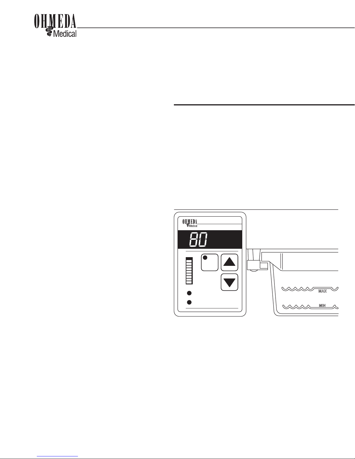
Figure 2-1 Control Panel ................................................................................................................................... 2-3
Figure 5-1 Disassembling the humidier ................................................................................................... 5-4
Figure 6-1 Tray and lid assembly..................................................................................................................6-10
Figure 6-2 Heat sink and valve assembly..................................................................................................6-11
Figure 6-3 Humidier controller disassembly.........................................................................................6-12
Figure 7-1 Lid and tray assembly...................................................................................................................7-1
Figure 7-2 Humidier controller ....................................................................................................................7-2
Figure 7-3 Heat sink and valve assembl ......................................................................................................7-3
Figure 7-4 Tray rails and mounting hardware........................................................................................... 7-4
Figure 7-5 Sensor assembly............................................................................................................................ 7-5
Figure 8-1 Servo-controlled HumidierWiring Diagram.......................................................................8-1
Figure 8-2 Power Supply Section - Cntrl/Display Brd Assy................................................................... 8-2
Figure 8-3 ControlSection - Cntrl/Display Brd Assy.................................................................................8-3
Figure 8-4 Display Section - Cntrl/Display Brd Assy................................................................................ 8-4
Figure A-1 Humidity sensor installation......................................................................................................A-3
Figure A-2 Rail installation ...............................................................................................................................A-4
Figure A-3 Humidity sensor cable attachment.........................................................................................A-5
Figure A-4 Power cord attachment...............................................................................................................A-6
Table of Contents
Valve Housing Re-assembly ..........................................................................................................................6-11
Humidier Controller Disassembly/Reassembly ...................................................................................6-12
Humidier Control/Display Board Removal/Installation ....................................................................6-13
Humidity Sensor Replacement.....................................................................................................................6-13
Sensor Calibration.............................................................................................................................................6-15
Valve Checkout...................................................................................................................................................6-16
Electrical Safety Check.....................................................................................................................................6-16
7/Illustrated Parts
Humidier Lid and Tray Assembly..................................................................................................... 7-1
Humidier Controller Assembly.........................................................................................................7-2
Humidier Heat Sink and Valve Assembly...................................................................................... 7-4
Humidier Rails and Mounting Hardware...................................................................................... 7-5
Humidity sensor ......................................................................................................................................7-6
8/Schematics
Appendix
A.1 Specications ................................................................................................................................................A-1
A.2 Servo-controlled Humidier Installation.............................................................................................A-3
A.3 Additional Safety Information.................................................................................................................A-7