ITA
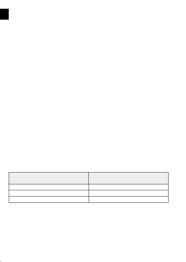
La temperatura dell’ambiente nel quale la macchina opera, è :
Sezione 2 - GARANZIA
La garanzia è valida contro difetti di fabbricazione per un periodo di ventiquattro(24) mesi dalla data d’acquisto (fa
fede il documento accompagnatorio della merce). La garanzia decade, e con essa ogni responsabilità diretta o indiretta,
qualora il prodotto sia stato manomesso o utilizzato in modo improprio, siano state fatte riparazioni o modiche da
personale non autorizzato, siano stati utilizzati ricambi non originali. I materiali resi per riparazione in garanzia vanno
resi in PORTO FRANCO.
Sezione 3 – NORME DI SICUREZZA
Non vi è nessuna controindicazione all’uso, se vengono osservate le normali precauzioni per prodotti di questo tipo
unitamente alle indicazioni riportate nel manuale USO E MANUTENZIONE.
Il motovibratore MVE può essere installato in qualsiasi posizione. Si consiglia di ssare il motovibratore su una zona
rigida per evitare che le vibrazioni indotte provochino rotture o incrinature; se ciò non fosse possibile, è necessario
utilizzare piastre e nervature di rinforzo.
Le procedure di taglio e di saldatura devono essere eettuate da personale qualicato. Idonee procedure di Hot-
Works(quali taglio o saldatura) e LOTO-lockout/tagout:procedura di disconnessione della macchina(segregazione
elettrica e meccanica), dovranno essere applicate per l’installazione in sicurezza dl moto vibratore. L’autorizzazione
all’esecuzione dei lavori a caldo DEVE essere data da personale tecnico specializzato e formato sul rischio di esplosione
da polveri.
La supercie di attacco deve essere piana (planarità max 0.25mm/max 0.01Inch) in modo che i piedi del vibratore
appoggino uniformemente e siano a perfetto contatto con la supercie di ssaggio, onde evitare tensioni interne capaci
di portare alla rottura dei piedi del moto vibratore.
Il livello di pressione acustica continua equivalente ponderata dei moto vibratori NON è mai superiore ai 90 dB(A)*
*Rilevazione eettuata in condizioni di normale funzionamento secondo la norma UNI EN ISO 11202.
Sezione 3.1 – INSTALLAZIONE
Per ssare il motovibratore, utilizzare bulloni (qualità 8.8), dadi (qualità 8.8) e rondelle piane cat.-A UNI6592. Utilizzare
una chiave dinamometrica regolata secondo quanto riportato nella tabella dei dati tecnici.
Ricordarsi che la maggior parte di guasti e avarie è dovuta a ssaggi e serraggi mal eseguiti.
Ancorare il motovibratore con adeguata catena di lunghezza cm. 15 o cavo metallico alla struttura.
Controllare prima della messa in marcia e dopo le prime 24 ore di lavoro:
ū Alimentare il vibratore e controllare con pinza amperometrica su tutte le fasi che l’assorbimento non superi il valore
di targa.
ū I bulloni di ssaggio del motovibratore e le saldature delle piastre e delle nervature di rinforzo.
ū Il cavo o catena di ancoraggio.
ū Il cablaggio di alimentazione.
Sezione 4 – NOTE OPERATIVE
COLLEGAMENTI ELETTRICI
IL COLLEGAMENTO ELETTRICO DEVE ESSERE EFFETTUATO ESCLUSIVAMENTE DA PERSONALE QUALIFICATO SECONDO LA EN/
IEC 60079-14 E CON ALIMENTAZIONE DISINSERITA. IL COLLEGAMENTO ATERRA E’OBBLIGATORIO.
Per i collegamenti dei moto vibratori fare riferimento allo schema“collegamenti elettrici”.
La rete di alimentazione ed il collegamento dei motovibratori devono essere conformi alle vigenti norme di sicurezza
stabilite dalle autorità competenti del luogo dove si svolge l’attività.
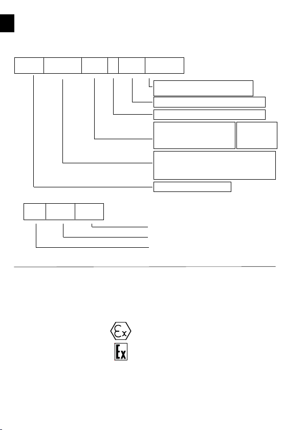
II3 D Ex tc IIICTx Db IP66
T.Amb -20/+40°C II3 D Ex tc IIICTx Db IP66
Serie N