01_OLI_00_IT_EN 7
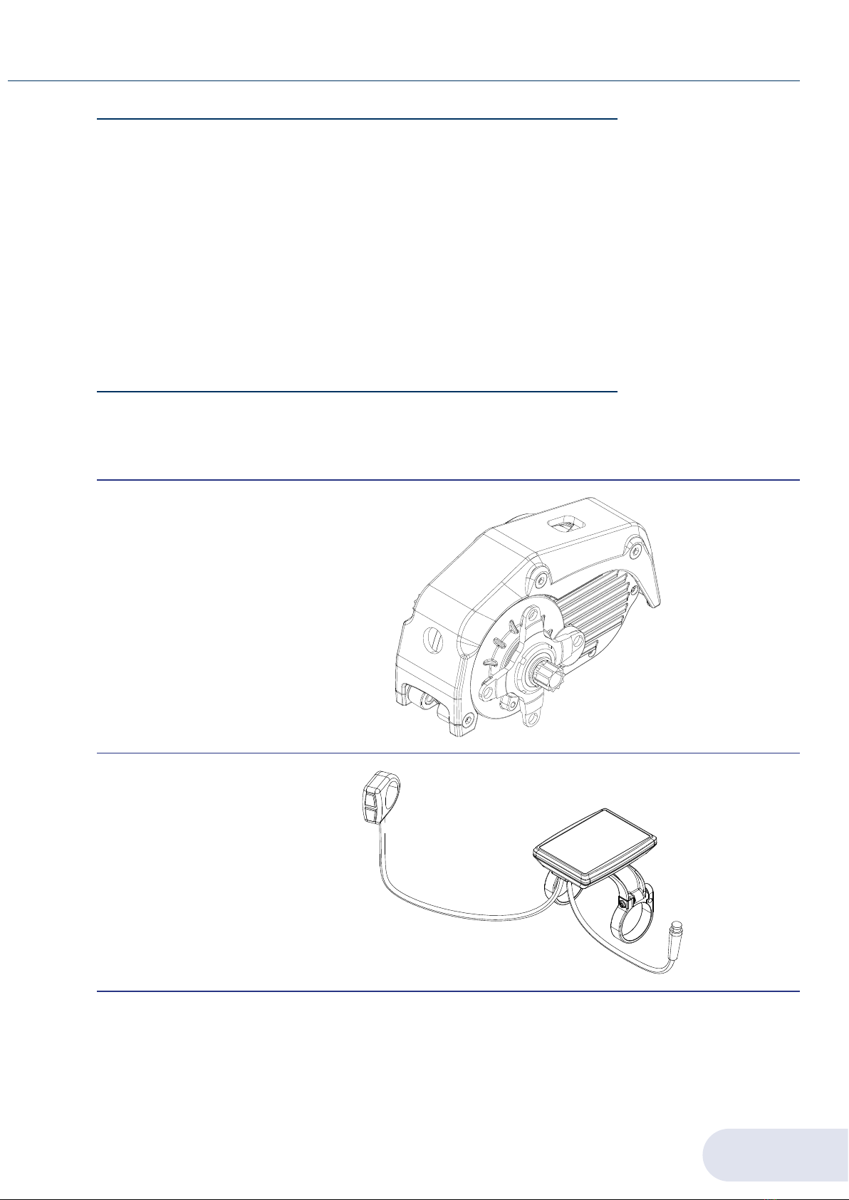
GENERAL INFORMATION 1SPORT
1.6. WARRANTY
The SPORT unit is covered by a warranty on the materials for a period of 36 months from the
date shown on the transport document. The buyer loses the right to the warranty in the event
of of incorrect installation or use or when they have made changes or repairs to the supply
without the authorisation of the manufacturer. Upon receipt of the product, the recipient
must check that there are no defects, damage deriving from transport and/or missing items
in the supply. Any complaints must be immediately notified to the manufacturer in writing
and countersigned by the carrier. Labour services such as sending a technician are excluded
from the warranty. Under no circumstances can compensation be claimed for damages. For
further clarifications on the warranty assistance conditions, refer to the sales contract.
IMPORTANT: Products sent for repair under warranty must be returned with prepaid
transportation to the manufacturer's factory.
1.7. TECHNICAL ASSISTANCE
Ordinary and extraordinary maintenance must take place in accordance with the instructions
contained in this manual. For any cases not included and for any kind of assistance, it is
recommended to contact the manufacturer directly, referring to the data reported on the
identification plate of the unit.
›model;
›serial number;
›year of manufacture.
The correct reference guarantees quick and precise answers.
IMPORTANT: The manufacturer declines all responsibility for damage to persons or property
resulting from improper use of the equipment, from errors in installation and use or from
inexperience, imprudence and negligence with respect to the indications/instructions given
in this manual.
IMPORTANT: The manufacturer declines all responsibility for damage to persons or property,
as well as to the malfunctioning of the unit if original spare parts and the recommended
cleaning and maintenance products are not used.
1.8. TRANSPORT, PACKAGING AND STORAGE
The drive unit and the HMI unit are supplied with dedicated packaging that prevents damage
due to transport.
Upon receipt of the goods, the customer must check if the model and quantity received
match the data on the order confirmation.
The components must be stored indoors in dry environments, protected from atmospheric
agents and at temperatures above -10°C.
IMPORTANT: It is the responsibility of the installer to properly dispose of the packaging in
compliance with the applicable laws in force.