OLiPower BRE-I-5K14K User manual

User Manual
BRE-I-5K14K
OLIPOWER ENERGY &AUTOMATION TECHNOLOGY

BRE-I-5K14K
User
Manual
About
This
Document
Issue
01
(2019-07-17)
i
About This Document
Purpose
This document describes the BRE-I-5K14K in terms of its installation,electrical
connections, commissioning, maintenance, and troubleshooting. Before installing and
operating the BRE-I-5K14K, ensure that you are familiar with the features, functions, and
safety precautions.
Intended Audience
This document is intended for:
⚫Installers
⚫Users
Symbol Conventions
The symbols that may be found in this document are defined as follows.
Symbol
Description
Indicates an imminently hazardous situation which, if not
avoided, will result in severe injury or death.
Indicates a potentially hazardous situation which, if not
avoided, could result in severe injury ordeath.
Indicates a potentially hazardous situation which, if not
avoided, may result in minor or moderateinjury.
Indicates a potentially hazardous situation which, if not
avoided, could result in equipment damage, data loss,
performance deterioration, or unanticipated results.
NOTICE is used to address practices not related to personal
injury.

BRE-I-5K14K
User
Manual
About
This
Document
Issue
01
(2019-07-17)
ii
Symbol
Description
Calls attention to important information, best practices,
and tips.
NOTE is used to address information not related to personal
injury, equipment damage, or environmental deterioration.
Change History
Changes between document issues are cumulative. The latest document issue contains all updates made
in previous issues.
Issue 01 (2019-07-17)
This issue is used for the first office application(FOA).

BRE-I-5K14K
User
Manual
Contents
Issue
02
(2017-12-12)
1
Contents
1 Safety Precautions.................................................................................................................................3
General Safety .......................................................................................................................................................................3
Disclaimer
...............................................................................................................................................................................3
Personnel Requirements
.......................................................................................................................................................... 4
Protect Labels ........................................................................................................................................................................ 4
Installation.............................................................................................................................................................................4
Electrical Connections...........................................................................................................................................................5
Operation...............................................................................................................................................................................6
Maintenance and Replacement..............................................................................................................................................6
2 Product Overview .................................................................................................................................7
2.1. Product Introduction.....................................................................................................................................................7
2.2. Appearance...................................................................................................................................................................8
2.3. Label Description........................................................................................................................................................11
3 Storage..................................................................................................................................................13
4 System Installation..............................................................................................................................14
4.1. Checking Before Installation ......................................................................................................................................14
4.2. Tools and Instruments................................................................................................................................................. 15
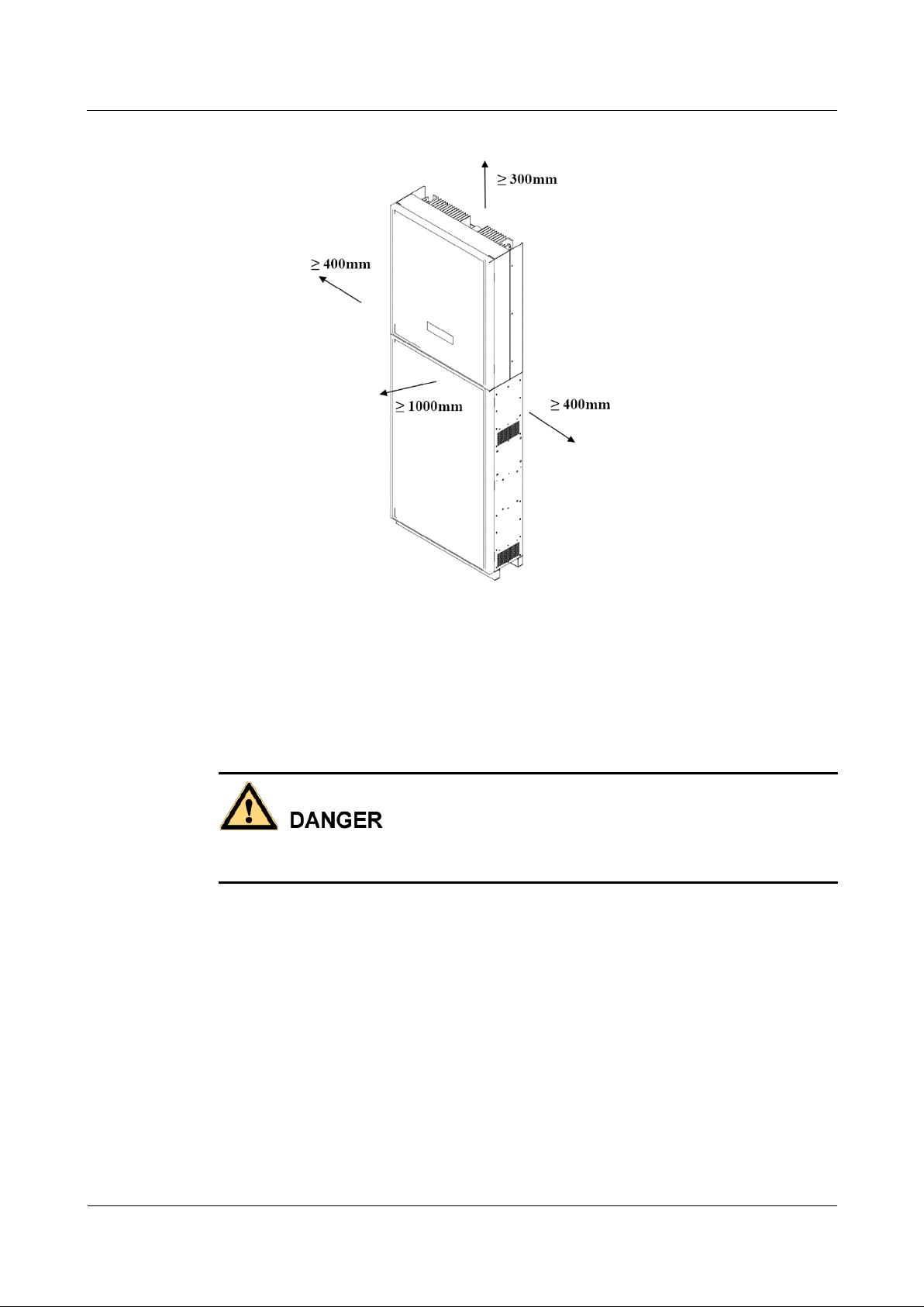
4.3. Determining the Installation Position .........................................................................................................................16
4.4. Installing the Mounting Bracket .................................................................................................................................18
4.5. Wall-Mounted Installation..........................................................................................................................................19
4.6. Installing the BRE-I-5K14K....................................................................................................................................... 21
5 Electrical Connections........................................................................................................................24
5.1 Preparing Cables.........................................................................................................................................................25
5.2 Installing Battery Box Cable.......................................................................................................................................28
5.3 Installing the main control box................................................................................................................................... 30
5.3.1 Installing the DC Input Power Cable..........................................................................................................................31
5.3.2 Installing the AC Input/output Power Cable (Grid)....................................................................................................33
5.3.3 Installing the EPS Cable............................................................................................................................................. 34
5.3.4 Installing the PE Cable ...............................................................................................................................................35
5.4 Install the cable between the main control box and the .............................................................................................. 37
5.5 DRM port and connections......................................................................................................................................... 39

Issue
02
(2019-07-17)
2
BRE-I-5K14K
User
Manual
Safety Precautions
6 System Commissioning.......................................................................................................................40
6.1 Checking Before Power-On........................................................................................................................................ 40
6.2 Powering on the System .............................................................................................................................................41
6.3 Powering Off the System............................................................................................................................................43
6.4 Operation Method.......................................................................................................................................................44
6.5 Power Quality Response Modes................................................................................................................................. 59
6.6 Remote monitoring..................................................................................................................................................... 66
7 Handling the BRE-I-5K14K...............................................................................................................67
7.1 Removing the BRE-I-5K14K .....................................................................................................................................67
7.2 Packing the BRE-I-5K14K.........................................................................................................................................67
7.3 Disposing of the BRE-I-5K14K .................................................................................................................................67
8 Technical Specifications......................................................................................................................68
8.1 DC Input..................................................................................................................................................................... 68
8.2 AC output ................................................................................................................................................................... 68
8.3 Battery ........................................................................................................................................................................69
8.4 Efficiency....................................................................................................................................................................69
8.5 General Data............................................................................................................................................................... 69
8.6 Dimension...................................................................................................................................................................70

Issue
02
(2019-07-17)
3
BRE-I-5K14K
User
Manual
Safety Precautions
1 Safety Precautions
General Safety
⚫Before performing operations, read through this manual and follow all the precautionsto
prevent accidents. The "DANGER," "WARNING," "CAUTION," and "NOTICE" marks
in this document do not represent all the safety instructions. They are only supplementsto
the safety instructions.
⚫Only certified electricians are allowed to install, connect cables for, commission,maintain,
and troubleshoot OLiPower products, and they must understand necessary safety
precautionsto avoid hazards.
When operating OLiPower equipment, in addition to following the general precautions
in this document, follow the specific safety instructions given by OLiPower. OLiPower
will not be liable for any consequence caused by violating the safety operation
regulations and design, production, and usage standards.
Disclaimer
OLiPower shall not be liable for any consequence caused by any of the following events:
⚫Transportation damage
⚫The storage conditions do not meet the requirements specified in this document.
⚫Incorrect storage, installation, or use
⚫Installation or use by unqualified personnel
⚫Failure to obey the operation instructions and safety precautions in thisdocument
⚫Operation in extreme environments which is not covered in this document
⚫Operation beyond specified ranges.
⚫Unauthorized modifications to the product or software code or removal of the product
⚫Device damage due to force majeure (such as lightning, earthquake, fire, and storm)
⚫The warranty expires, and the warranty service is not extended.
⚫Installation or use in environments which are not specified in relatedinternational
standards

Issue
02
(2019-07-17)
4
BRE-I-5K14K
User
Manual
Safety Precautions
Personnel Requirements
Only certified electricians are allowed to install, connect cables for, commission,maintain,
troubleshoot, and replace the BRE-I-5K14K.
⚫Operation personnel should receive professional training.
⚫Operation personnel should read through this document and follow all the precautions.
⚫Operation personnel should be familiar with the safety specifications of theelectrical
system.
⚫Operation personnel should understand the composition and working principles ofthe
grid-tied PV system and local regulations.
⚫Operation personnel must wear proper personal protective equipment (PPE).
Protect Labels
⚫Do not scrawl or damage any labels on the BRE-I-5K14K enclosure because they
contain important information about the safe operation.
⚫Do not scrawl or damage the nameplate on the BRE-I-5K14K enclosure because it
contains important product information.
Installation
Never operate the BRE-I-5K14K under power duringinstallation.
⚫Ensure that the BRE-I-5K14K is not connected to a power supply or powered on
before finishing the installation.
⚫Toallow proper heat dissipation and installation, maintain appropriate clearances
between the BRE-I-5K14K and other objects, as shown in Figure 1-1. If you have
any questions about the clearances, consult local technical support engineers.

Issue
02
(2019-07-17)
5
BRE-I-5K14K
User
Manual
Safety Precautions
Figure 1-1 Installation space
⚫Ensure that the BRE-I-5K14K is installed in a well-ventilatedenvironment.
⚫Ensure that the BRE-I-5K14K heat sinks are free fromblockage.
⚫Do not open the front panel of the BRE-I-5K14K.
⚫Do not remove the terminals and ports at the bottom of the BRE-I-5K14K.
Electrical Connections
Before connecting cables, ensure that the BRE-I-5K14K is secured in position and
notdamaged in any way. Otherwise, electric shocks or fires may occur.
⚫Ensure that all electrical connections comply with local electricalstandards.
⚫Obtain approval from the local utility company before using the BRE-I-5K14K to
generate electricity in grid-tied mode.
⚫Ensure that the cables used in a grid-tied PV system are properly connected andinsulated
and meet all specification requirements.

Issue
02
(2019-07-17)
6
BRE-I-5K14K
User
Manual
Safety Precautions
Operation
High voltage may cause an electric shock, which results in serious injury, death, or
severe property damage from the BRE-I-5K14K in operation. Strictly comply with
thesafety precautions in this document and associated documents when operating
theBRE-I-5K14K.
⚫When the BRE-I-5K14K is powered on for the first time, only certified electricians
can perform a quick setting. Incorrect settings may affect the normalBRE-I-5K14K
operation and cause the BRE-I-5K14K to conflict with the countrycertification.
⚫When the BRE-I-5K14K is operating, do not disconnect underload.
⚫Do not touch an energized BRE-I-5K14K because the heat sink has a hightemperature.
⚫Follow local laws and regulations when operating the equipment.
Maintenance and Replacement
High voltage may cause an electric shock, which results in serious injury, death, or
severe property damage from the BRE-I-5K14K in operation. Before maintenance,
power offthe BRE-I-5K14K. Strictly comply with the safety precautions in this
document andassociated documents to operate the BRE-I-5K14K.
⚫Maintain the BRE-I-5K14K with sufficient knowledge of this document, proper tools,
and testing equipment.
⚫Before performing maintenance tasks, power off the BRE-I-5K14K and wait at
least5 minutes.
⚫Temporary warning signs or fences must be placed to prevent unauthorized peoplefrom
entering the site.
⚫If the BRE-I-5K14K is faulty, contact your supplier.
⚫The BRE-I-5K14K can be powered on only after all faults are rectified. Failing to do so
may escalate faults or damage the device.
⚫Observe ESD precautions and wear ESD gloves during maintenance.

Issue
02
(2019-07-17)
7
BRE-I-5K14K
User
Manual
2 Product Overview
2 Product Overview
2.1.Product Introduction
Function
BRE-I-5K14K is a single-phase grid-connected PV string inverter and energy storage system.
It can store the DC power generated by the PV string into the battery, or convert the DC
power generated by the PV string or the stored energy of the battery into AC power. Power
is input to the grid.
Networking Application
The BRE-I-5K14K applies to a residential rooftop grid-tied system. Typically, a grid-tiedsystem
consists of the PV string, grid-tied inverter, AC switch, and power distribution unit.
Figure 2-2 Network diagram
Indicates a power cable, indicates the power flow direction, and indicates asignal
cable.
(A) PV string
(B) DC switch
(C) BRE-I-5K-14K
(D) AC switch
(E) Residential power
distribution board
(F) Energy meter
(G) Residential power meter
(H) Power grid
(I) Residential load

Issue
02
(2019-07-17)
8
BRE-I-5K14K
User
Manual
2 Product Overview
Supported Power Grid
Power grid types supported by the BRE-I-5K14K include TN-S, TN-C, TN-C-S, and TT. In aTT
power grid, the N-PE voltage should be lower than 30V.
Figure 2-3 Power grid types
2.2.Appearance
Front View
Figure 2-4 Front view
(1) LED 1 (2) LED 2 (3) LED 3 (4) LED4 (5) Front panel

Issue
02
(2019-07-17)
9
BRE-I-5K14K
User
Manual
2 Product Overview
Table 2-1 LED description
Type
Name
Status
Meaning
Maintenance
indicator
Steady red
BESS failure or maintenance
required
Solar indicator
Steady orange
Solar equipment working
Grid indicator
Steady green
Export energy to the grid
Steady orange
Import energy from the grid
Off
Grid off
Battery indicator
Steady green
Battery charging
Steady orange
Battery discharging
Blinking green
Wake up
Off
Others
Rear View
Figure 2-5 Rearview
(1) Main control box mounting bracket (2) Battery box mounting bracket
(3) Heatsink

Issue
02
(2019-07-17)
10
BRE-I-5K14K
User
Manual
2 Product Overview
Dimensions
Figure 2-7 Dimensions of the enclosure
Figure 2-8 Dimensions of the main control box mounting bracket
Figure 2-9 Dimensions of the battery box mounting bracket

Issue
02
(2019-07-17)
11
BRE-I-5K14K
User
Manual
2 Product Overview
2.3.Label Description
Symbols
Table 2-3 Label description
Symbol
Name
Meaning
Burn warning
Do not touch a running
BRE-I-5K14K because
the cover is hot when
the BRE-I-5K14K is
running.
Delay discharge
High voltage exists
after the BRE-I-5K14K
is power on. Only
qualified and trained
electrical technicians
are allowed to perform
operations on the BRE-
I-5K14K.
Residual voltage exists
after the BRE-I-5K14K
is powered off. It takes
5 minutes for the BRE-
I-5K14K to discharge
to the safe voltage.

Issue
02
(2019-07-17)
12
BRE-I-5K14K
User
Manual
2 Product Overview
Symbol
Name
Meaning
Refer to documentation
Reminds operators to
refer to the documents
shipped with the
BRE-I-5K14K.
Grounding
Indicates the position for
connecting the protective
earthing (PE) cable.
Operation warning
Do not remove the
connector or antenna
when the BRE-I-
5K14K is running.
BRE-I-5K14K serial
number (SN) label
Indicates the serial
number of BRE-I-
5K14K.
The labels are for reference only.

Issue
02
(2019-07-17)
13
BRE-I-5K14K
User
Manual
3 Storage
3 Storage
The following requirements should be met when the BRE-I-5K14K needs to be stored before
installation:
⚫Do not unpack the BRE-I-5K14K.
⚫Keep the storage temperature at –40°C to +70°C and the humidity at 5%–95% RH.
⚫The BRE-I-5K14K should be stored in a clean and dry place and be protected from dust
and water vapor corrosion.
⚫A maximum of 2 BRE-I-5K14Ks can be stacked. To avoid personal injury or
device damage, stack BRE-I-5K14Ks with caution to prevent them from falling
over.
⚫Regular inspection is required during the storage. Replace the packing materialswhen
necessary.
⚫After long-term storage, inspection and testing conducted by qualified personsare
necessary before the BRE-I-5K14K is put intouse.

Issue
02
(2019-07-17)
14
BRE-I-5K14K
User
Manual
4 System
4 System Installation
4.1. Checking Before Installation
Outer Packing Materials
Before unpacking the BRE-I-5K14K, check the outer packing materials for damage, such as holes
and cracks, and check the BRE-I-5K14K model. If any damage is found or theBRE-I-5K14K model
is not what you requested, do not unpack the package and contact your supplier as soon as possible.
It is advised to remove the packing materials within 24 hours before installing the
BRE-I-5K14K.
Package Contents
After unpacking the BRE-I-5K14K, check if the contents are intact and complete. If any damage is
found or any component is missing, contact yoursupplier.
For details about the number of contents, see the Packing List in the packingcase.

Issue
02
(2019-07-17)
15
BRE-I-5K14K
User
Manual
4 System
4.2. Tools and Instruments
Category
Tools and Instruments
Installation
Hammer drill (with a Ф10
mm drill bit)
Torque socket wrench (open
end: 13 mm, applicable for
M8 bolts; torque range: 0–15
N•m)
Torque wrench (open end: 13
mm; torque range: 0–1.5
N•m)
Diagonal pliers
Wire stripper
Torque screwdriver (head:
M4 or M6; torque range: 0–5
N•m)
Rubber mallet
Utility knife
Cable cutter
Crimping tool (model:
H4TC0001; manufacturer:
Amphenol)
Open-end wrench (model:
H4TW0001; manufacturer:
Amphenol)
Cable tie
Vacuum cleaner
Multimeter (DC voltage
measurement range ≥ 600 V
DC)
Marker

Issue
02
(2019-07-17)
16
BRE-I-5K14K
User
Manual
4 System
Category
Tools and Instruments
Measuring tape
Bubble or digital level
Hydraulic pliers
Heat shrink tubing
Heat gun
N/A
PPE
Safety gloves
Safety goggles
Anti-dust respirator
Safety shoes
N/A
N/A
4.3. Determining the Installation Position
Basic Requirements
⚫The BRE-I-5K14K is protected under IP54 and can be installed indoors oroutdoors.
⚫Do not install the BRE-I-5K14K in a place where a person can easily come intocontact
with its enclosure and heatsink, because these parts are scorching duringoperation.
⚫Do not install the BRE-I-5K14K in areas with flammable or explosivematerials.
⚫Do not install the BRE-I-5K14K at a place within children'sreach.
⚫The BRE-I-5K14K will be corroded in salt areas, and the salt corrosion may cause a
fire.Do not install the BRE-I-5K14K outdoors in salt areas. A salt area refers to the
region within 500 meters from the coast or prone to the sea breeze. The region prone to
sea breezevaries depending on weather conditions (such as typhoons and monsoons) or
terrains (suchas dams and hills).

Issue
02
(2019-07-17)
17
BRE-I-5K14K
User
Manual
4 System
Installation EnvironmentRequirements
⚫The BRE-I-5K14K must be installed in a well-ventilated environment to ensure good
heat dissipation.
⚫When installed under direct sunlight, performance de-rate may be initiated dueto
the additional temperature rise.
⚫Install the BRE-I-5K14K in a sheltered place or install an awning over theBRE-I-5K14K.
Mounting StructureRequirements
⚫The mounting structure where the BRE-I-5K14K is installed must be fireproof.
⚫Do not install the BRE-I-5K14K on flammable buildingmaterials.
⚫Ensure that the installation surface is solid enough to bear the weight load.
⚫In residential areas, do not install the BRE-I-5K14K on drywalls or walls made of
similar materials which have a weak sound insulation performance because the noise
generated by the BRE-I-5K14K is noticeable.
Installation AngleRequirements
The BRE-I-5K14K only can be wall-mounted. The installation angle requirements are as
follows:
⚫Install the BRE-I-5K14K vertically.
⚫Do not install the BRE-I-5K14K at forward-tilted, back tilted, side tilted, horizontal, or
upside-down positions.
Figure 4-1 Installation angle
Table of contents