manuals.online logo
Brands
  1. Home
  2. •
  3. Brands
  4. •
  5. Oliver Flugmodellbau
  6. •
  7. Toy
  8. •
  9. Oliver Flugmodellbau FRESH Instructions for use

Oliver Flugmodellbau FRESH Instructions for use

FRESH
Sail flight model for F3-RES
Span: 2000 mm
Wing area: 35,6 dm²
Weight RES: from 435 gr.
Weight E-RES: from 465 gr.
irfoil: G36mod/G37mod
Web: www.oliver-flugmodellbau.de Email: [email protected]
1
Construction manual
(2016 ugust 28th, Oliver Matzen)
Notes before construction work
Because of the simple construction, it is possible to produce the model very quickly.
Only little grinding work is required.
To build the model you need usual model construction tools:
●Balsa knife,
●Sanding block with sandpaper 100 and 400 grid,
●Jigsaw with metal blade,
●File, rasp,
●Drill,
●Pliers,
●Scissors,
●Needles, clamps and weights,
●and a balsa plane is also useful.
n even stable board approx. 30cm x 100cm is required as construction pad.
For a finish with covering film is an iron, a pair of scissors and a sharp razor
necessary. long steel ruler is helpful.
For the assembly and finish you need:
●Superglue low viscosity appr. 20 gr and activator,
●5 minutes epoxy,
●Wood glue,
●Covering film appr. 2 m*0,6 m,
●Scotch tape 15 mm wide
for flying you need:
●a remote control with a minimum of three channels
●2 servos appr. 10 gr
●1 Servo appr. 5 gr
●1 small receiver
●1 receiver battery
●1 servo extension leads
Slightly trim weight may also be necessary and tape is required to secure the outer
wing.
For the high Start a suitable high starting rubber with cord, ground anchors, ring
and a little flag is used. The launch system will develop no more than 4kg force.
(Vendors for bungees are e.g. www.setatech.de, www.emc-vega.de,
www.hobbyking.com (the blue)
2
Construction is fun but keep in mind:
●You are resposible for your own healthiness.
●almost all adhesi es contain sol ents an other olatile substances,
care for adequate entilation!
●Be carefully in the use of superglue! Fingers and eylids are glued
together faster than you do not mind!
●The processing of CFRP caused finest coal dust which must not be
inhaled or swallowed!
●Wash your hands when coal dust adheres to your fingers!
●Do not blow the coal dust from the building board, remo e the dust
with a acuum cleaner!
●Note the operating instructions by the manufacturers and suppliers.
●Handling tools can cause injury.
●Operation of an Aircraft model can cause accidents.
●Construction and operation of a flight model must be learned.
●For beginners, it is necessary that an experienced person helps.
●For damages and accidents that will arise in connection with the
construction and operating of the model, "Oli er Flugmodellbau" do
not take any resposibility.
.... and here we go with building fun!
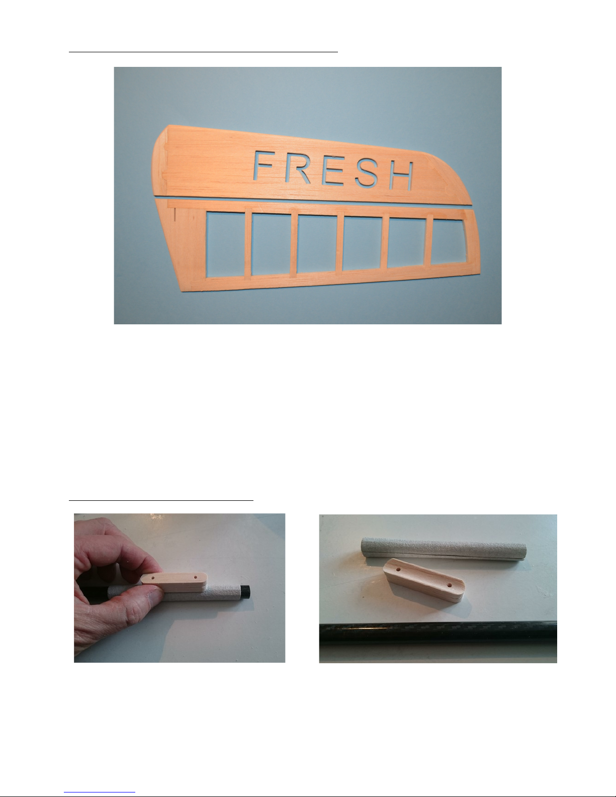
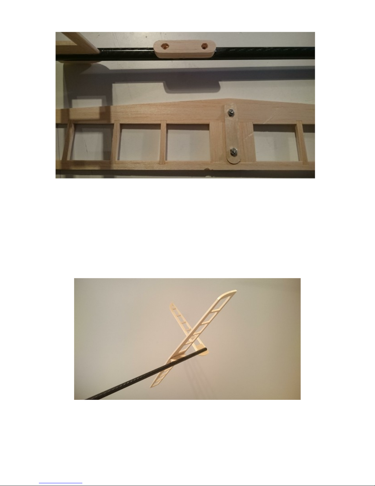
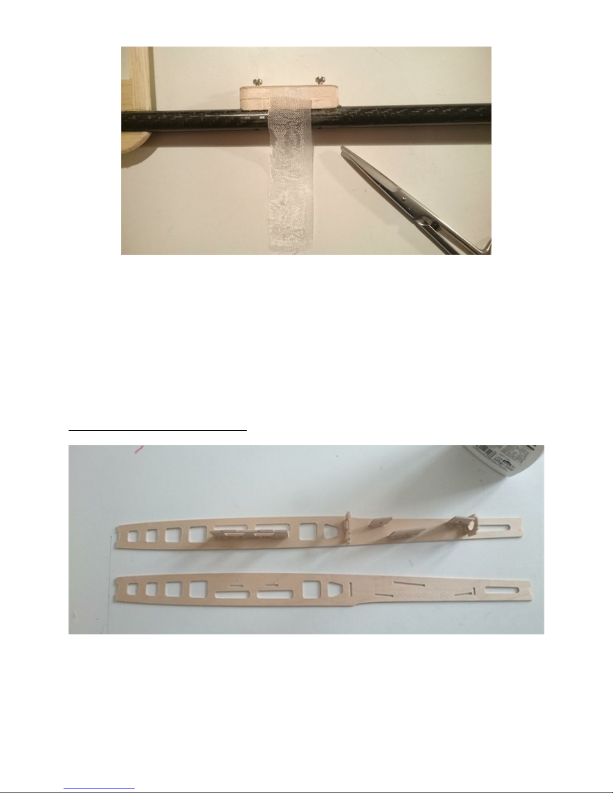
Construction of horizontal stabilizer (ele ator)
Separate components with a sharp balsa knife from balsa and connection webs
remove from the components (little grinding).
Stuck together and stick together. Use superglue in order to save weight.
Leading edge and tip grind around. Tail edge grind tapered.
Planing in the hinge region with the balsa plane at 45 degree.
The control horn is glued with superglue after ironing the covering film.
3
Construction of ertical stabilizer (rudder)
Separate components with a sharp balsa knife from balsa and connection webs
remove from the components (little grinding).
Stuck together and stick together. Use superglue in order to save weight.
Leading edge and tip grind around. Tail edge grind tapered.
Planing in the hinge region with the balsa plane at 45 degree.
The control horn is glued with superglue after ironing the covering film.
Construction of the tail boom
Elevator support stick together of two balsa parts. Then grinding a trough according
to the 12mm tail boom diameter. If something goes wrong during grinding, don't
worry, the kit contains additional support parts.
4
Place the support centered under the tail boom and measure at the tube ends the
same distance to the building board. So it is checked that the trough was grind
parallel to the top of the support.
Tail boom sanded before bonding in the area of the support with 400 grain
sandpaper and remove the sanding dust.
Stick the support with 5 minute epoxy to the tail
boom. The two holes in the support are in alignment
with the two holes in the tail boom. Push the fixed
front part of the rudder into the slot of the tail boom.
Vertically align the tail edge of the rudder to the tail
boom.
Stick the "Fresh" rudder with superglue into the tail
boom.
Superglue activator ist helpful in this case.
5
The layer of plywood which is glued to the elevator support is first screwed with two
M3 metal screws (not included in the kit) and the plastic nuts to the elevator.
Use M(etric) 3mm*20mm metal screws, which can be easily unscrewed after
gluing. Later during flying use the plastic screws to save weight.
Press the elevator to the support to transfer the contours of the nuts on the
suppport.
ccording to the footprint of the nuts on the support edit the support with a balsa
knife to get space for the nuts in the support.
Before gluing the plywood layer and the nuts with the support, check the right
angle of the horizontal and vertical stabilisator.
If it is not rectangular, you can grind the surface of the support and corrected it
accordingly.
Glue the plywood with 5 minute epoxy to the support.
6
The elevator-support is fixed with 25gr/m² glass fabric strips in addition to the tail
boom.
Grind the tail boom in the area of the glass fabric with 400 grain sandpaper and
remove the sanding dust.
To glue the glass fabric use thin superglue.
First fix the glass fabric near the top of the balsa support with superglue. Then drag
the tissue around the tail boom and soak it with superglue.
Construction of the fuselage
Glue the fuselage formers, servo plate, wing screw and ballast carrier with wood
glue or super glue together.
7
For the electric glider version 4*4mm triangular strips (approx 4-5 cm long each)
are glued to the stringers.
fter the formers and other internals are dried, glue the 4*4mm Balsa stringers
with wood glue into the fuselage.
In the area of the wing leading edge the stringers are overlapping. Grind the top
stringer to fit the airfoil shape.
The hook board is glued together of two parts.
The board is not neccessary in the electric
glider version.
8
Glue the hook board with wood glue between the lower fuselage stringers.
Glue balsa sides of the fuselage with wood glue on the plywood sides
The upper and lower fuselage planking is made of 2mm balsa. Cut 3cm wide strips
from the 2mm balsa sheet.
The wood grain of the fuselage planking is transverse to the direction of flight.
9
For the cockpit cover the 2mm Balsa planking is cut out wider as the fuselage
(approx 4cm). Glue the plywood reinforcement in the center of the plating. Stick
the carbon flat profile only on the first 3 cm into the slot and strengthen the glue
area additionally with a little glass cloth. The glass cloth can be glued with thin
super glue.
In the glider ersion, before gluing, the plywood reinforcement is slightly
narrowed to the front (red lines), so that the plywood fits between the
upper stringers.
The fixed plywood tongue over the lid to the left and the flexible carbon flat over
the lid to the right.
10
To close the cover, the spring is first pushed under the fuselage planking and the lid
by lifting simultaneously slid over the planking.
The cover is pushed back until the front tongue can be slid under the fuselage
planking.
s long as the lid is not ironed, the edges of the cover are to be treated carefully.
fter ironing the edges are sufficiently strong to pull the lid to open up.
Sand and clean the tail boom slightly for bonding to the fuselage.
Before gluing the tail boom into the fuselage slide the eight balsa cone pieces on
the tail boom without gluing them.
11
Insert the tail boom into the fuselage and align the elevator parallel with the center
wing section witch is screwed on the fuselage. Place the jigs Z2 under the Tail boom
and check the right attitude for forward fuselage.
Tail boom and balsa cone pieces stick together with super glue each by each.
fter gluing treat the balsa conical with rasp and sandpaper.
During rasping and grinding protect the tail boom with tape.
12
Construction of the wing center section
Center rib is made of two
balsa and two plywood
ribs.
The balsa/plywood hybrid
ribs stick together with
superglue.
Production tolerance of the
carbon tubes is +/-
0,2mm.
Therefore it is possible,
that the holes in ribs has
to be edit by grinding to
make them fit to the
tubes.
With a roll made of 100
grain sandpaper it is done
quickly.
Ribs and half rips sorted
before pushing on the
tube.
13
Grind the spar slightly with
sandpaper 400 grain
carefully and clean the
spar before pushing the
ribs on the tube.
The center rib has to be
right angular to the spar.
Push all ribs on the tube
spar and adjust with the
slots in the tail edge and
the jigs. Put the 3mm
carbon nose tube into the
ribs noses.
Do not push the end ribs
on the tube spar now.
djust all ribs carefully
and and use some weights
to press the ribs to the
building board.
Glue ribs with tube spar
and nose tube and trailling
edge with superglue.
Grind the holes incline for
the tube spar in the end
ribs according to the
dihadral.
14
Use the dihadral jig for
gluing the end ribs.
Hybrid rib and Plywood rib
glue together.
Glue the ribs carefully to
the Spars.
Do not try to sa e glue
when gluing ribs to the
spars.
Install 4x4mm balsa strips for
the spoiler frame.
Install the plywood
reinforcements for the center
wing screwing.
Produce filling pieces made
of remaining balsa material
for the nose bar.
15
Install 1mm planking on
the lower side with wood
glue.
The wood grain of the
planking is transverse to
the direction of flight.
Install the balsa pieces on top
of the wing screwing
reinforcements.
Grind the balsa pieces to the
airfoil shape.
Install the 1mm upper
planking with wood glue.
Drill the two 4mm holes
through the center rib for
the wing screws.
16
Install the two little balsa
pieces for the spoiler
magnets.
The spoiler support F19
adjust to the frame. Ironing
the Cover film on the
supports before gluing the
supports into the wing.
3mm magnets glue with
super glue.
3mm magnets glue into the
spoiler.
Be sure that the magnets
do pull and do not push
each other.
Shorten the carbon
tubes with a metal
blade.
fter all grind the ribs
carefully to smoth the
surface.
17
Construction of inner sektion and outer sektion of the outer wing
The inner sektion of the outer wing has to be build in normal position.
The outer sektion of the outer wing has to be build upside down !
Stick the hybrid ribs with
plywood and balsa wood with
superglue together.
Sand slightly and clean the tube
spar the entire length with 400
grit sandpaper.
Slide spacers to the 8mm tube
spar and glue with superglue.
The distance of the rings
according to the distance of the
full ribs.
Possibly adjust the diameter of
the rings.
Insert 5 minute epoxy in the
12mm tube and insert the 8mm
tube spar into the 12mm tube
spar and glue. Use also glue
between the rings.
Ribs on the spar pushing and
adjust to the tail strip and the
rib jig for the inner sektion and
glue with superglue.
Do not push the end ribs on the
spar.
18
Detail photo of the transitition
of the 8mm spar into the
12mm tube spar.
fter all ribs are aligned neatly, the wings with some weight rests on the building
board, glued with superglue spar and leading edge with the ribs.
Glue the end ribs
according to the dihadral
jigs.
Glue the spar carefully
with the ribs.
Saw off over standing
tubes and grind the
surface carefully.
The outer sektion of the outer wing has to be build upside down ! Make
sure that is made a left and a right outer wing sektion.
lign ribs with the jig and the
trailing edge.
Push nose tube into the ribs
noses. lign carefully and glue
with superglue.
19
When dried turn the outer wing
around in normal position and use
the dihadral jig to glue the end
ribs.
The wingtip is made of three formed
balsa pieces. Grind the tip with
sandpaper.
The dihadral giving FRP piece in the
outer wing is glued with enough 5
minute epoxy into the tube spars.
The end ribs glued together with
wood glue.
Construction of wing conector
The fixture is made of rings and
spacers.
The small holes in the spacers showing
the side with the dihadral shape.
On the dihadral side is the 6mm bore
above of the ring. In the other ring is
the 6mm bore down.
20

Popular Toy manuals by other brands

Eduard MiG-3 Assembly manual

Eduard

Eduard MiG-3 Assembly manual

Protocol Nauticus 6182-3R instruction manual

Protocol

Protocol Nauticus 6182-3R instruction manual

Walkera HM 22e User handbook

Walkera

Walkera HM 22e User handbook

Rayline S04-1 manual

Rayline

Rayline S04-1 manual

Opitec Dragonfly 102.894 manual

Opitec

Opitec Dragonfly 102.894 manual

Eduard RA-5C Vigilante Assembly instructions

Eduard

Eduard RA-5C Vigilante Assembly instructions

Tiger Electronics Dear Diary III 59919 instructions

Tiger Electronics

Tiger Electronics Dear Diary III 59919 instructions

Hoffmann Hurricane Assembly manual

Hoffmann

Hoffmann Hurricane Assembly manual

REVELL KIT 1970 Assembly manual

REVELL

REVELL KIT 1970 Assembly manual

KidKraft 63180 Assembly instructions

KidKraft

KidKraft 63180 Assembly instructions

Eduard C-130J-30 interior Assembly instructions

Eduard

Eduard C-130J-30 interior Assembly instructions

Carson SPY HAWK Basic Video instruction manual

Carson

Carson SPY HAWK Basic Video instruction manual

LEGO NEXO KNIGHTS 70326 Building instructions

LEGO

LEGO NEXO KNIGHTS 70326 Building instructions

Fisher-Price V7873 manual

Fisher-Price

Fisher-Price V7873 manual

LEXIBOOK CR550 series instruction manual

LEXIBOOK

LEXIBOOK CR550 series instruction manual

Big Backyard DELUXE LOWER CLUBHOUSE F24700 Installation and operating instructions

Big Backyard

Big Backyard DELUXE LOWER CLUBHOUSE F24700 Installation and operating instructions

Trix Minitrix MaK G 1000 BB manual

Trix

Trix Minitrix MaK G 1000 BB manual

MTHTrains BIG BOY operating instructions

MTHTrains

MTHTrains BIG BOY operating instructions

manuals.online logo
manuals.online logoBrands
  • About & Mission
  • Contact us
  • Privacy Policy
  • Terms and Conditions

Copyright 2025 Manuals.Online. All Rights Reserved.