Omega Engineering FSV100 Series User manual

Compsny
Technologies
h
An
OMEGA
OMEGg
Operator’s Manual
fl
I
a
@
I
fx
8
I
fx
@
I
m
03
m
03
m
@
I
fx
03
m
@
fx
03
a
8
I
fx
@
I
m
8
m
@
eneral Purpose Solenoid Valves
6
G
FSV200
Series
FSVlOO
and
YCE

CJSl194MAJBA
3599RUSH
pH and Conductivity
Data Acquisition Systems
Electric Heaters
Environmental Monitoring
and Control
Call for Your FREE Handbook Request Form Today: (203)
&
Force
Flow and Level
&
Encyclopedias
Temperature
Pressure, Strain
6TU,
England
Telephone: 44 (1455) 285520 FAX: 44 (1455) 283912
The OMEGA Complete Measurement and
Control Handbooks
l-800-USA-WHENSM
TELEX: 996404 EASYLINK: 62968934 CABLE OMEGA
Servicing Europe: United Kingdom Sales and Distribution Center
25 Swannington Road, Broughton Astley, Leicestershire
LE9
/
l-800-622-BESTSM
Engineering Service: l-800-872-9436
/
l-800-TC-OMEGASM
Customer Service: l-800-622-2378
/
5Al
Telephone: (203) 359-1660 Telephone: (514) 856-6928
FAX: (203) 359-7700 FAX: (514) 856-6886
Sales Service: l-800-826-6342
H7L
Lava1
(Quebec)
Servicing USA and Canada: Call OMEGA Toll Free
USA
Canada
One Omega Drive, Box 4047 976 Bergar
Stamford, CT 06907-0047

FSV200
Series
General Purpose Solenoid Valve
Page
Chapter 1 Introduction
. . . . . . . . . . . . . . . . . . . . . . . . . . . . . . . . . . . . . . . . . . . . . . . . . . . . . . . . . . . . . . . . . . . . . . . . . . . . . . . . . . . . . . . . . . . . . . . . . . . . . . . . . . . . . .
1
1 .1
Unpack ing
..................................................................................................................
1
1.2
Desc ri p ti on
.................................................................................................................
1
1.3
Fea tu res
.................................................................................................................. 2
1.4
Ava ilab le M ode ls
......................................................................................................... 2
1.5
Typ ica l App lica tions
..................................................................................................... 3
Chapter
2
Parts of the Solenoid Valve
......................................................................................
4
Chapter 3 Installation
................................................................................................................
4
Chapter 4 Troubleshooting Guide
........................................................................................... 5
Chapter 5 Spare Parts List
.......................................................................................................
6
Chapter 6 Specifications
..........................................................................................................
7
I
FSVIOO
Table of Contents

Notes

Piston-
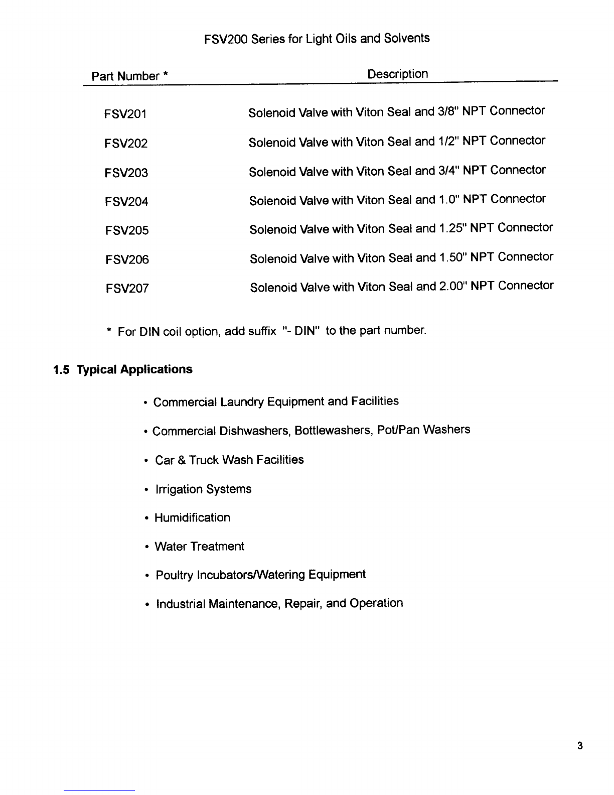
TypeSolenoidValvescovermostindustrialapplications.Atwo-wayvalvecontrolstheflowof
fluidthroughasinglepassage. Ithastwoports,aninletandanoutlet.Anormallyclosedvalve
doesnotpassfluidunlessitisenergized.Thereisfailsafepositivevalveclosingintheevent
ofpowerfailurethatpreventsfloodingoroverfilling.
Thesevalvescoverawiderangeofoperatingpressuresandtemperatures.5PSIto150PSI
pressureandtemperaturesto195°Faffordsbroadapplicationandtremendousflexibility. The
longlifebronzecastingsandwaterproofcoilsinsureperformanceconsistencyforalonglife.
Sincethevalvesareveryrugged,theyprovidelowincidenceofdowntimeandmaintenance.
Minimumpressuredropinternaldesignofthisvalveassuresexceptionalflowperformance.
FSV200
SeriesTwo-WayNormallyClosedPilotOperated
FSVIOO
and
(1)
Operator’sManual(1)
Ifyouhaveanyquestionsabouttheshipment,pleasecallOMEGACustomerServiceDepart-
ment.Whenyoureceivetheshipment,inspectthecontainerandequipmentforsignsofdam-
age.Noteanyevidenceofroughhandlingintransit.Immediatelyreportanydamagetothe
shippingagent.
NOTE
Thecarrierwillnothonoranyclaimsunlessallshipping
materialissavedforinspection.Afterexamining
andremovingcontents,savepackingmaterialandcarton
intheeventreshipmentisnecessary.
1.2 Description
TheOMEGA@
.l
Unpacking
RemovethePackingListandverifythatyouhavereceivedallequipment,includingthefollow-
ing(quantitiesinparentheses):
GeneralPurposeSolenoidValve
Chapter 1 Introduction
1

BUNA
N/EPDMSealand2.00”NPTConnector
*ForDINcoiloption,addsuffix“-DIN”tothepartnumber.
2
FSVI 07
SolenoidValvewith
BUNA N/EPDMSealand1.50”NPTConnector
BUNA
N/EPDMSealand1.25”NPTConnector
FSV106
SolenoidValvewith
FSVI 05
SolenoidValvewith
.OO”
NPTConnector
BUNA
N/EPDMSealand1
FSVI 04
SolenoidValvewith
3/4” NPTConnector
N/EPDM
Sealand
BUNA
FSVI 03
SolenoidValvewith
l/2”
NPTConnector
BUNA
N/EPDMSealand
FSV102
SolenoidValvewith
318”
NPTConnector
BUNA
N/EPDMSealand
FSVI 01
SolenoidValvewith
FSVI 00SeriesforWater
PartNumber* Description
FSVlOOlFSV200 solenoidvalveshavethefollowingfeatures:
??
2-wayNormallyClosed
??
Pilot-Operated
??
Piston-Type
??
BronzeConstruction
??
VarietyofVoltages
??
MaximumTemperatureof195°F
??
MaximumPressure150PSI
1.4
Available Models
OMEGAEngineering,Inc.hasthefollowingmodelswiththefollowingcharacteristics:
1.3 Features
The

&
TruckWashFacilities
IrrigationSystems
Humidification
WaterTreatment
PoultryIncubators/WateringEquipment
IndustrialMaintenance,Repair,andOperation
“- DIN”tothepartnumber.
1.5 Typical Applications
CommercialLaundryEquipmentandFacilities
CommercialDishwashers,Bottlewashers,Pot/PanWashers
Car
*
ForDINcoiloption,addsuffix
FSV207
SolenoidValvewithVitonSealand2.00 ”NPTConnector
FSV206
SolenoidValvewithVitonSealand1.50 ”NPTConnector
FSV205 SolenoidValvewithVitonSealand1.25 ”NPTConnector
.O”
NPTConnector
3/4” NPTConnector
FSV204 SolenoidValvewithVitonSealand1
FSV203
SolenoidValvewithVitonSealand
112”
NPTConnector
FSV202
SolenoidValvewithVitonSealand
3/8” NPTConnector
DescriDtion
FSV201
SolenoidValvewithVitonSealand
FSV200 SeriesforLight
OilsandSolvents
PartNumber*

2”
NPT
Chapter 3 Installation
Besuretoadheretothefollowingwheninstallingyoursolenoidvalve:
4
Arrowonvalvebodyindicatesdirectionofflow.
Applywrenchonlyonendofvalvebeingconnected;
(leverageonothervalvepartscancausedamage)
Installinhorizontalpositionwithsolenoidvertical.
Makeelectricalconnectionsincompliancewithelectricalcode.
CAUTION
Becertainelectricpowerisofthesamevoltage
andcyclesasmarkedonsolenoid.
lYz”,
I%“,
(TEFLON)
-PISTON BODY
Figure 2-2. I”,
BOHET
G
PLUNGER ASSEMBLY
PISTON SPRING
SPLIT RING
--SOLENOID
BONNET
SPRING
W
AS
HER
SOLENOID
314”
NPT
l/2”,
310”,
WASHER
NUT
Figure 2-1.
SEAT
SPLtT
RING
(TEFLON,
PISTON BODY
FSVlOO/200
Series
PLUNGER ASSEMBLY
PISTON SPRING
Chapter
2
Parts
of the Solenoid Valve

&
2 ”
replacevalve
2.Pistonseatwasher
takesadeepset Replaceseatwasher
Caution:
Do
notapplyvoltagetosolenoidcoilthathasbeenremovedfromvalve.
l-1/2”,
l-l/#“,
l”,
314”
replacepiston
l/2”,
&
3/8”,
6”
gapin
splitpistonrings.
Installnewbonnet
Trimasrequired
Failuretoclosewhen
solenoidde-energized
1.
PistonRingbinding
betweenbodybore
andpiston
Removepistonandplace
ringingroove,theninsert
pistoninbody
Removepistonandclean
outmatter
2.
Foreignmatterlodged
onbodyseat
3.
Foreignmatter
preventingplunger
fromseating
Cleanoutforeignmatter
atplungerseathole
4.
Plungertipisbroken
orbadlyworn Replaceplunger
assembly
Leakage 1.Plungerseathole
eroded
/I
Chapter 4 Troubleshooting Guide
Problem PossibleCause CorrectiveAction
Failuretoopenwhen
solenoidengergized
1.
Lowvoltageatsolenoid
(below85%ofrated
voltage)
Insurepropervoltageat
solenoid
2.
Solenoidfailure Checkforexcessive
voltageatsolenoid
Replacesplitrings
3.
Wornrings
Pressuredropless
than5PSI Increasepressure
differentialto5PSI
4.
5.
Bonnetbent
6.
Shouldhaveapprox-
imately1

N/A
87408 85649 85650
PistonAssembly 7735504 7730002 7643103 7646902 7647002
PistonSeatWasher 84689 84688 84794 85614 85612
6
N/A
“0”
Ring
11/2”
2”
PlungerAssembly 74777 74777 74777 74777 74777
11/4”
&
314”
1”
112”
CL
3ia”
FSVIOO
ExceptFollowingPartsofViton:
I
SamePartsas
FSVZOO
8249801
84048
84571
84518
86030 76745 76750
7673801
,
1
8222 2
85Oi9Oi
(2
Req’d)
PistonSeatWasher 8222301
PistonSeatWasher
Nut
1
N/A
82224 82224 82224
TeflonSplitPistonRing
FSVI
00
7319503 7319503 7319503 7319503
73026 83192 83192 83192
x”92”
NPT Connector Stvles
W’*l
3/8”*1/2”*3/&1”~1
30”
lead
wires.
Fitsallvalvesizes.
ConsultFactoryforothervoltagesandcoilswithground
wire.
l/2”
NPTConduit
outletand
Chapter 5 Spare Parts List
Coilwith

-
Viton)
RefertoflowCapacityCharts Refertoabovefigures Refertoabovetable
(FSV200
Series
Vat
coils
Bronze,Teflon,EPDM
(FSV200)
23Watts,120
(FSVI 00):Oil/and
Solvents
90X)
Water
(OX
to
l-l/4" l-112"
2"
2.00 2.12 3.50 7.20
7.25 10.00 13.75
0.91
0.96
1.59
3.27 3.29 4.55 6.25
Maximum Viscosity:
Minimum Pressure:
Maximum Presure:
Temperature Range:
Medium:
Power:
Wetted Parts:
CvValues: Dimensions: Weight:
17.8
Centistokes
5PSI 150PSI
32°Fto195”
'I
314"
1
112"
2"
Cv
Factor 2.3 3.3 7.5 9.8
15
28 39
Note:(CvFactor)Theamountofwaterthatwillflowthroughthevalvewitha1PSIpressuredropat60F.This shouldbeusedfor
a
comparisonflow.
Weight
Lbs.
Kgs.
318"
'I
l-114" l-112"
314”
1
l/2"
318”
FSVlOO:
For fluids compatible with bronze, 430 F Stainless Steel, Ethylene Propylene, and Teflon
Pipe
Size
CL
2”
I%“,
1?4”,
314”
Figure 6-2. 1”,
112”,
8
3/W’,
I
Figure 6-i.
i-t
I
f’k
I
IT----
r--C---+
0
F
ri
0
OO/FSVZOO
Series
FSVI
Chapter 6 Specifications

kO.002
8
1
0.25-l
3.45
1
1.5-9.5
1
Viton
I
2.000
FSV207
2.00 kO.002
I
Viton
I
1.5-9 0.2-0.4
I
1.500
.50
I
FSV206
I
*0.002
FSV205
1.25 1.250 Viton 0.8-5.8 0.2-0.5
*0.002
FSV204
1 .oo
1.250 Viton 0.6-4.5 0.1-0.25
*0.005
0.6-4.5
0.1-0.25
314
0.849 Viton
FSV203
.--
0.439
I
Viton 0.85
_ .
t
l/2
_ .-
I
I
FSV202
1
- _ --.
.
.-__
I
I
.__
I.
._ .
I
.
__
,
I”-2”
2-5 sec.
3/8”-314”
1-3 sec.,
0-
5 10 20 30 40 60 80 100 125 150
Pressure Drop Across the Valve in PSI
* Valves require minimum 5 PSI pressure differential
for reliable operation.
* Must be installed in horizontal piping with solenoid in vertical position.
* Valve should be sized to flow requirement, not pipe size.
* Average closing time:
:8
;i
E
125
100
0
15 0
.E
20 0
3175
250
k
E
450
400
350
300
I%“,
2” NPT
I%“,
l”,
64.
314”
NPT Figure
l/2”,
3/W’,
125 150
Pressure Drop Across the Valve in PSI
Figure 6-3.
IO 20 30 40 60
SO
100
0
5
IA
20
10
5
30
h.
.E
4 0
g
5 0
6o
E
80
70
(con?)
Flow Capacity Charts
100
90
Specifications

Notes

0
Copyright1994OMEGAENGINEERING,INC.Allrightsreserved.Thisdocumentationmaynotbecopied,photocopied,
reproduced,translated,orreducedtoanyelectronicmediumormachine-readableform,inwholeorinpart,withoutprior
writtenconsentofOMEGAENGINEERING,INC.
mation
available BEFORE contacting OMEGA:
1.
2.
3.
P.O. number to cover the COST of the
repair/calibration,
Model and serial number of product, and
Repair instructions and/or specific problems
relative to the product.
OMEGA’spolicyistomakerunningchanges,notmodelchanges,wheneveranimprovementispossible.Thisaffords
ourcustomersthelatestintechnologyandengineering.
OMEGA is a registered trademark of OMEGA ENGINEERING,
INC.
infor-
NON_WARRANTY
REPAIRS OR
CALIBRA-
TION,
consult OMEGA for current repair/
calibration charges. Have the following
1.
2.
3.
PO. number under which the product was
PURCHASED,
Model and serial number of the product
under warranty, and
Repair instructions and/or specific prob-
lems relative to the product.
FOR
bMEGA
ENGINEERING Customer Service
Department. BEFORE RETURNING ANY PRODUCT(S) TO OMEGA, PURCHASER MUST OBTAIN AN
AUTHORIZED RETURN (AR) NUMBER FROM OMEGA ’S CUSTOMER SERVICE DEPARTMENT (IN
ORDER TO AVOID PROCESSING DELAYS). The assigned AR number should then be marked on the
outside of the return package and on any correspondence.
FOR
WARRANTY
RETURNS, please have the
following information available BEFORE con-
tacting OMEGA:
/
INQUIRIES
Direct all warranty and repair requests/inquiries to
the
triacs.
OMEGA is glad to offer suggestions on the use of its various products.
Nevertheless,
OMEGA only warrants that the parts manufactured by it will be as specified and free of
defects.
OMEGA MAKES NO OTHER WARRANTIES OR REPRESENTATIONS OF ANY KIND WHAT-
SOEVER, EXPRESSED OR IMPLIED, EXCEPT THAT OF TITLE AND ALL IMPLIED WAR-
RANTIES INCLUDING ANY WARRANTY OF MERCHANTABILITY AND FITNESS FOR A
PARTICULAR PURPOSE ARE HEREBY DISCLAIMED.
LIMITATION OF LIABILITY: The remedies of purchaser set forth herein are exclusive and
the total liability of OMEGA with respect to this order, whether based on contract, war-
ranty, negligence, indemnification, strict liability or otherwise, shall not exceed the
purchase price of the component upon which liability is based. In no event shall
OMEGA be liable for consequential, incidental or special damages.
Every precaution for accuracy has been taken in the preparation of this manual; however, OMEGA
ENGINEERING, INC. neither assumes responsibility for any omissions or errors that may appear
nor assumes liability for any damages that result from the use of the products in accordance with
the information contained in the manual.
SPECIAL CONDITION: Should this equipment be used in or with any nuclear installation or activity,
purchaser will indemnify OMEGA and hold OMEGA harmless from any liability or damage whatso-
ever arising out of the use of the equipment in such a manner.
RETURN REQUESTS
WARRANTY
OMEGAwarrantsthisunittobefreeofdefectsinmaterialsandworkmanshipandtogivesatisfac-
toryserviceforaperiodof13
months
from date of purchase. OMEGA Warranty adds an addition-
alone(1)monthgraceperiodtothenormal
one (1) year product warranty
to cover handling
and shipping time. This ensures that OMEGA ’s customers receive maximum coverage on each
product. If the unit should malfunction, it must be returned to the factory for evaluation. OMEGA ’s
Customer Service Department will issue an Authorized Return (AR) number immediately upon
phone or written request. Upon examination by OMEGA, if the unit is found to be defective it will
be repaired or replaced at no charge. However, this WARRANTY is VOID if the unit shows evidence
of having been tampered with or shows evidence of being damaged as a result of excessive corro-
sion; or current, heat, moisture or vibration; improper specification;
misapplication;misuseor
otheroperatingconditionsoutsideof
OMEGA’s control. Components which wear or which are
damaged by misuse are not warranted. These include contact points, fuses, and

/
1194
&
Dissolved Oxygen Instruments
Ml948
pH,
Conductivity
&
Wastewater Treatment
&
Water Monitors
Industrial Water
&
Tubing
Air, Soil
&
Control Instrumentation
Refractometers
Pumps
D
Laboratory Heaters
ENVIRONMENTAL MONITORING AND CONTROL
Metering
m
Flexible Heaters
&
Band Heaters
w
Immersion
&
Strip Heaters
w
Cartridge
B
Heating Cable
D
Recorders, Printers & Plotters
HEATERS
D
Datalogging Systems
&
Compatibles
w
Plug-in Cards for Apple, IBM
@
Communications-Based Acquisition Systems
m
Data Acquisition and Engineering Software
&
Conductivity Equipment
DATA ACQUISITION
pH
@’
Industrial
&
Pumps
m
Controllers, Calibrators, Simulators
D
Benchtop/Laboratory Meters
&
Accessories
pH
Electrodes, Testers
b
&
Batch Controllers
H/CONDUCTIVITY
B
Totalizers
Turbine/Paddlewheel Systems
m
m
Air Velocity Indicators
&
Flow Computers
m
Rotameters, Gas Mass Flowmeters
&
Accessories
FLOW/ LEVEL
@
Instrumentation
m
Displacement Transducers
&
Pressure Gauges
m
Load Cells
&
Strain Gages
B
Transducers
&
Process Monitors
Infrared Pyrometers
PRESSURE/STRAIN FORCE
&
Ice Point References
Recorders, Controllers
&
Thermistor
Calibrators RTD
&
Assemblies
Wire: Thermocouple,
&
Thermistor Probes, Connectors, Panels
la
Thermocouple, RTD
E
Ia
D
I
Need for
Process Measurement and Control?
OMEGA...Of Course!
TEMPERATURE
I
Find EverythingWhere Do

This manual suits for next models
1
Table of contents