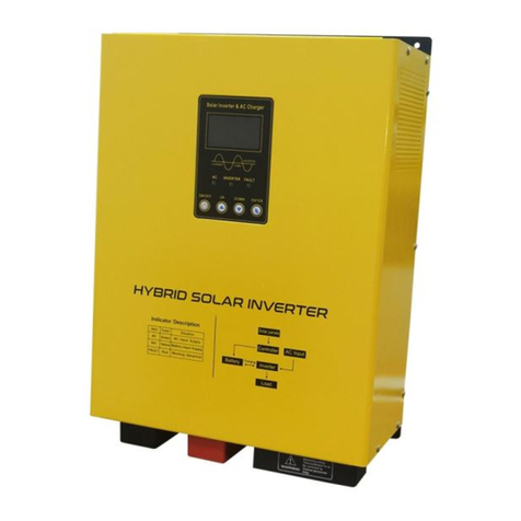
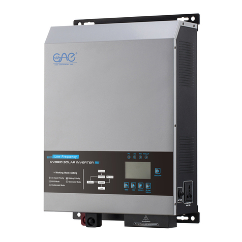
One-Solar LSI Series Quick start guide

SI Series 1.5-20KW
Pure Sine Wave
Low Frequency
Solar Hybrid UPS Inverter
with built-in PWM Solar Charger
Fax:+86 757 8258 9791
Tel:+86 757 8258 0189

Ⅰ.Operating Instruction---------------------------2
Ⅱ.Outlook drawing of inverter---------------------2
---------------------4Ⅲ.Description of front board
-----4Ⅳ. Function setting and meaning of the button
--------------6Ⅴ.Connection way of input & output
-------------------------8Ⅵ.Battery wiring diagram
-----------------12Ⅶ. Soalr module wiring diagram
-----------------------15Ⅷ. Care and maintenance
--15Ⅸ. Convenient method of maintenance & fixing
-------------------------------16Ⅹ.Technical Data
Content
Ⅰ.Operating Instruction
Ⅱ.Outlook drawing of inverter
1.1500W / 2000W / 3000W Series
2
1-1. Open-package inspection
1). After opening the package, please check the accessories and components,
including operation manual and checking whether the inverter is in good condition? If
inverter broken or components missing, do not turn on the machine, feedback to the
carrier or supplier.
Note:
1). Please keep the box and packing materials in case the use in future.
2). The product is very heavy (check accessories as reference), please
be careful when carrying.
1-2. Installation notice:
1). The products should be well-ventilated, away from water and the corrosive and
combustible gases.
2). Do not set it in a corner. Ensure the bottom of the front panel, the rear panel fan
outlet and the side of the machine are well-ventilated.
3). The environment temperature should remain 0 - 40℃.
4). If the machine is operated under low temperature environment, it will cause
water condense, the machine can work only in a absolute dry condition
otherwise there will be a electric shock.
5). Install the inverter near the mains input socket or nearby the switch, to
draw out plugs then cut off mains supply once there is an emergency.
Attention:
1). Loads should be turned off before connecting to inverter and turned on one by
one after connecting completed.
2). The inverter should be connected to a socket with a corresponding current
protection.
3). All power sockets should link with ground protection.
4). No matter input power cable inserts to mains socket or not, the inverter will
also continue outputing possibly, turning off the inverter can not guarantee
there is no current inside the machine. In order to make sure to cut off the
output of inverter, you should turn off all the switches then turn off the main
supply.
5). To load inductive appliances such as electromotor, displayer and laser printer,
inverter capacity should be twice as loading machine’s rated power at least.

2.4000W / 5000W / 7000W Series
3.10KW / 15KW / 20KW Series
AC voltage
Working mode
Output voltage
Buzzer
Load
Battery
Ⅲ.Description of front board
Meaning of indicate lamp&button
4
Solar module
Ⅳ. Function setting and meaning of the button
ON/OFF Button:
Battery type Charging current(24V*2;48V*4;96V*8;108V*9;120V*10)
GEL U.S.A. 13.7V
A.G .M.1 13.4V
A.G .M.2 13.7V
Sealed Lead Acid 13.6V
Gel European 13.8V
Open Lead Acid 13.8V
Calcuim (Open)13.6V
De sulphation cycle 14.5V
01 Normal Mode - AC input priority to supply the load and batteries, battery supply the
loads without AC input.
02 Saving Mode - AC input advanced to supply the load and the battery, battery supply the
loads without AC input. But the load must >5% of the inverter capacity. otherwise the machine will
continue to startup and shutdown.
03 Battery Mode - Battery priority to supply the load, when battery is low of power or voltage,
will automatically switch to AC mains supply, when the battery full of charge, automatically transfer to
the battery supply.
Press this button to display the data below: Output voltage , Battery capacity ,
Output frequency , Load capacity , solar input voltage ,
Solar charging current , Solar charging power .
Note:(The Max. charging current is 15A,from 0% to 100% )
FunctionUp Down
AC mode
Battery mode
Fault
Turn on or turn off
AC input
3
Function Button :
(P1 Working mode, P2 Battery type choose,
P3 Charging current adjust, P4) →OK
→
5 sec.→ setting(P0),
Model P1: AC
02:Auto 03: Battery →OK
→
Model P2: →OK
Type
Model P3: → →OK
0-15A
→
Model P4: →OK
or
Note: Restart the inverter after each setting.
3 sec. ON→3 sec. OFF→
or press two times can back to the main interface.

5
1.Main interface data:
2.Function setting interface:
Back panel illustration
Ⅴ.Connection way of input & output
Connect with AC input and load output by connecting terminal, load oputput
can connect both by terminal blocks and output plug.
Note: Output plug only can connect with each load less than 1500W.
DC -
DC +
AC INPUT
AC OUTPUT
Battery negative polarity connection
AC input connection
Universal socket output pr connection terminal output
Battery positive polarity connection
USE ONLY WITH 250V FUSE AC input and output over current protection
DC OUTPUT DC output terminal
SOLAR IN Solar panels and connection
1.1500W / 2000W / 3000W Series wiring diagram
6
L
N
L
N
Rs232
Main interface Solar power Solar charging current
Output frequency Load capacity Solar panel voltage
Battery capacity Note:Inverter without the data of the solar panels.
Back to interface Working mode Battery type
Buzzer Charging current

4
7
Ⅵ.Battery wiring diagram:
1.12V series battery wiring
BATTERY
12V-100AH
8
2. 4000W / 5000W / 7000W Series wiring diagram
3. 10kW / 15kW / 20kW Series wiring diagram
BATTERY I N
ON/OF F
BATTERY
CHA RGER
INP UT PROT ECT
Rs23 2
A C
INP UT
A C
OUT PUT
BATTERY IN
ON/ OFF
BATT ERY
Rs2 32
A C
INPUT
A C
OUTPUT
ON/ OFF
AC IN PUT
L
N
L
N
Rs2 32
2.24V series battery wiring
L
N
L
N
Rs2 32
BATTERY
12V-100AH
BATTERY
12V-100AH

910
3.48V series battery wiring
L
N
L
N
Rs2 32
BATTERY
12V-100AH
BATTERY IN
ON/OFF
BATTERY
CHA RGER
INP UT PROT ECT
Rs2 32
A C
INPUT
A C
OUTPUT
4
BATTERY
12V-100AH
BATTERY
12V-100AH
BATTERY IN
ON/OFF
BATTERY
CHA RGER
INP UT PROT ECT
Rs2 32
A C
INPUT
A C
OUTPUT
4.96V Series battery wiring
BATTERY IN
ON/OFF
BATTERY
CHA RGER
INP UT PROT ECT
Rs2 32
A C
INPUT
A C
OUTPUT
BATTERY
12V-100AH
BATTERY
12V-100AH
BATTERY
12V-100AH
BATTERY
12V-100AH
BATTERY
12V-100AH
BATTERY
12V-100AH
BATTERY
12V-100AH
BATTERY
12V-100AH
BATTERY
12V-100AH
BATTERY
12V-100AH
BATTERY
12V-100AH
BATTERY
12V-100AH
BATTERY
12V-100AH
BATTERY
12V-100AH
BATTERY
12V-100AH

5.High voltage series battery wiring
BATTERY
BATTERY IN
ON/ OFF
BATTE RY
Rs2 32
A C
INPUT
A C
OUTPUT
ON/ OFF
AC INPUT
220VDC
BATTERY
BATTERY IN
ON/ OFF
BATTE RY
Rs2 32
A C
INPUT
A C
OUTPUT
ON/ OFF
AC INPUT
192VDC
1.12V Series wiring diagram
Ⅶ.Soalr module wiring diagram:
L
N
L
N
Rs2 32
LCD
2.24V Series wiring diagram
18V solar panel 1PC
L
N
L
N
Rs2 32
LCD
36V solar panel 1PC
11 12

BATTERY IN
ON/OFF
BATTERY
CHA RGER
INP UT PROT ECT
Rs23 2
A C
INP UT
A C
OUT PUT
3.48V Series wiring diagram
LCD
L
N
L
N
Rs2 32
36V solar panel 2PCS
4.48V Series wiring diagram
36V solar panel 2PCS
LCD
BATT ERY IN
ON/OF F
BATT ERY
CHAR GER
INPU T PROTE CT
Rs232
A C
INP UT
A C
OUT PUT
5.96V Series wiring diagram
36V solar panel 2PCS
LCD
5.192V/220V Series wiring diagram
36V solar panel 8PCS
BATTERY IN
ON/ OFF
BATTE RY
Rs2 32
A C
INP UT
A C
OUT PUT
ON/ OFF
AC IN PUT
13 14

15
Switch off with loads
Terminal heating
Switch on failure
Alarm when switch
on
Ⅸ. Convenient method of maintenance & fixing:
Fault
Battery no energy or overload
Fault connection with city power
or battery
Fault or loose connection
Recoverable fuse popup
Battery no energy or overload
Cause
Press fuse back
Fasten again
Charge battery or reduce loads
Check connection with battery or
connect again
Charge battery or reduce loads
Solution
Buzzer scream 2 secs
every 1 sec stop
Over temperature alarm (85 alarm-90
shut down) Check if fan heat dissipation hole jammed
Fan twirls sometimes
fast as well as slowly
Fan twirls fast when inside temperature
reaches 45 degree, twirls slowly when 42
degree
Normal phenomenon, fan is under intelligent
control
No city power input
Without solar data
display
Solar panel loose connection or reverse
connection
Check the cables, or the positive and
negative pole reverse connection
Battery full charged or wrong installation
Check the data of the battery or the
installation of the panels
No solar charging
Ⅷ. Care and maintenance
16
1). This series of products seldom need to be fix. The standard model battery is
like a adjusting tap. Low maintenance, ensuring better life only by charging
often. When connecting to mains supply, no matter whether the inverter is on
or not, it still keeps charging for battery, and provides over charge, over
discharge protection.
2). If there has been long time no using the inverter, it would be better to charge
on after four to six months.
3). The normal working life of battery is 3 or 5 years, if it doesn’t work, please
change as early as possible by professionals.
4). Don’t change the single battery , changing the battery should according to
the suppliers instructions.
5). In normal, the battery should discharge then recharge after working each four
or six months , start to charge and finish discharge, standard charging time
should be more than 12 hours.
6). In high temperature area, the battery should be charged and discharged
every 2 months and the standard charging time is more than 12 hours.
Note:
1). Before changing battery, must turn off inverter and disconnect the
mains supply.
2). Remove metal object like ring, watch etc.
3). Please don’t put the metal objects on the battery.
4). It is a normal phenomenon that the wire will appear a small spark when
connecting to the inverter, but it will not does harm to the people or the
inverter.
5). Be attention to do not reverse connecting between the positive pole and the
negative pole.
If connected to the generator, the following steps should be required.
1).To start the generator till it runs steadily, then connect the generator output to
the inverter input terminal. And turn on the inverter step by step according to
the operating instruction. After the inverter starts, connect the load one by one
to the inverter.
2).Please select the inverter capacity two or three times over than the
capacity of the generator.
Ⅹ.Technical Data
Model
LSI-152
Rated Power
1500W 3000W 4000W 5000W
7000W
Input Voltage
(175-265)VAC
Frequency
45-65Hz
Voltage
AC220V+2%(battery mode)
Output
Frequency
50/60Hz+1%(battery mode)
Output waveform
Pure sine wave
Efficiency
>85%
Battery type
Optional
Normal battery voltage
12/24/48VDC 24/48/96VDC
Protection
Transform
Interactive
Overload
Communication
RS-232
Temperature
-2 0— +75℃
Environment
Humidity
Size L*W*H (mm)
G.W.(N.W) (kg)
Max.PV charging current
LSI-202
2000W
0--15A(Optional)
10%-90%
Over load, short - circuit, battery high and low voltage,AC high and low voltage protection.
Solar panel reverse connection, over current, over temperature protection.
410*220*410mm 470*270*525mm
17kg 25kg
32.5kg
46kg
52kg
57kg
LSI-302 LSI-402 LSI-502
LSI-702
10000W
LSI-103
15000W
LSI-153
20000W
LSI-203
Max.PV input voltage
25/50/100VDC 50/100/200VDC
Max.AC charging current
30A-50A-60A(Optional)
450VDC
540*300*655mm
50A-100A(Optional)
192/220/240VDC
0--10A(Optional)
70kg 80kg 90kg
Over load 110%~120% maintain 30s switch the output of the bypass,over 160% maintain 300ms.
This manual suits for next models
9
Table of contents
Other One-Solar Inverter manuals
Popular Inverter manuals by other brands

Siemens
Siemens SINAMICS G120 Original instructions

Dongguan Shengyang industrial
Dongguan Shengyang industrial SY-GWV-500W user manual

Hoymiles
Hoymiles DTU-WLite user manual

PV Powered
PV Powered PVP260kW Installation & operation manual

Powerspot
Powerspot Lanyard user manual

Kestrel
Kestrel IVR-1200LBKS user manual

Porta Source
Porta Source IG800W Operator's manual

TOOLINE
TOOLINE HY70i user manual

Western Co
Western Co W-HHS-3000 Quick installation guide

Siemens
Siemens SINAMICS G180 Installation and operating instructions

Westerbeke
Westerbeke WTA-20-614 specification

Sungrow
Sungrow SG50KTL-M-20 Quick installation guide