FCS LOBO 1200 User manual

Solar Inverter
1200VA/2400VA
V. 2.1
1. Introduction
Thank you for purchasing the solar inverter. This simple solar inverter is designed to power
your home appliances or precious 3C electronics. It also can handle motor-type loads with high
surge power such as vacuums, small freezers, or drills. With built-in solar charger, it can
convert solar power to battery power and provide continuous power to connected equipment
during night time.
2. Product Overview
1. Power Switch
2. Status indicators
3. LCD display
Please see the Operation section for the details of LED and LCD display.
4. Output receptacles
5. Charge current selector: 10 A or 20 A
6. AC input
7. Circuit breaker
8. External battery connectors
9. Solar panel terminal
10. Solar charging indicator
11. Charger fault indicator
3. Important Safety Warning (SAVE THESE INSTRUCTIONS)
Before using the inverter, please read all instructions and cautionary markings
on the unit, this manual and the batteries.
General Precaution-
Install the UPS in a protected area that is free of excessive dust and has adequate air flow.
Please place the UPS away from other units at least 20 cm to avoid interference. Do NOT
operate the UPS where the temperature and humidity is outside the specific limits. (Please
check the specs for the limitations.)
Quick Guide
Conventions used:
WARNING! Warnings identify conditions or practices that could result in personal injury;
CAUTION! Caution identify conditions or practices that could result in damaged to the
unit or other equipment connected.
FCS - LOBO SOLAR INVERTER

CAUTION! The unit is designed for indoor use. Do not expose this unit to rain, snow or
liquids of any type.
CAUTION! To reduce risk of injury, only use qualified batteries from qualified distributors or
manufacturers. Any unqualified batteries may cause damage and injury. Do NOT use old or
overdue batteries. Please check the battery type and date code before installation to avoid
damage and injury.
WARNING! It's very important for system safety and efficient operation to use appropriate
external battery cable. To reduce risk of injury, external battery cables should be UL certified
and rated for 75°C or higher. And do not use copper cables less than 10AWG. Below is the
external battery cable reference according to system requirements.
Table 1 Minimum Recommended Battery Cable Size versus Length
Model
Typical Amp.
1 meter (one-way)
Dia-mm
1200VA
75 A
AWG 3
5.8272
2400VA
75 A
AWG 3
5.8272
Table 2 External Battery Cable Size Reference
AWG
Dia-mm
Ohms/Kft
0000(4/0)
11.684
0.049
000(3/0)
10.405
0.0618
00(2/0)
9.2657
0.0779
0(1/0)
8.2513
0.0983
1
7.348
0.1239
2
6.5436
0.1563
3
5.8272
0.197
4
5.1893
0.2485
5
4.6212
0.3133
CAUTION! Do not disassemble the inverter. Contact with the qualified service center when
service or repair is required.
WARNING! Provide ventilation to outdoors from the battery compartment. The battery
enclosure should be designed to prevent accumulation and concentration of hydrogen gas at
the top of the compartment.
CAUTION! Use insulated tools to reduce the chance of short-circuit when installing or working
with the inverter, the batteries, or other equipments attached to this unit.
CAUTION! For battery installation and maintenance, read the battery manufacturer's
installation and maintenance instructions prior to operating.
Personnel Precaution -
CAUTION! Careful to reduce the risk or dropping a metal tool on the batteries. It could spark
or short circuit the batteries and could cause an explosion.
CAUTION! Remove personal metal items such as rings, bracelets, necklaces, and watches
when working with batteries. Batteries can produce a short circuit current high enough to
make metal melt, and could cause severe burns.
CAUTION! Avoid touching eyes while working near batteries.
CAUTION! Have plenty of fresh water and soap nearby in case battery acid contacts skin,
clothing, or eyes.
CAUTION! NEVER smoke or allow a spark or flame in vicinity of a battery.
CAUTION! If a remote or automatic generator start system is used, disable the automatic
starting circuit or disconnect the generator to prevent accident during servicing.
4. Specifications
MODEL
1200
2400
CAPACITY
1200 VA / 720 W
2400 VA / 1440 W
INPUT
Voltage
230 VAC
Voltage Range
90-280 VAC
OUTPUT
Voltage Regulation (Batt. Mode)
+/-10%
Transfer Time
20 ms typical
Waveform
Simulated Sine Wave
BATTERY
Battery Voltage
12 VDC
24 VDC
Floating Charge Voltage
13.7 VDC ± 2%
27.4 VDC ± 2%
Maximum AC Charge Current
10 A or 20 A
SOLAR CHARGER
Charging Current
50 A max.
Maximum PV Array Open Circuit Voltage
40 VDC
60 VDC
PHYSICAL
Dimension (DxWxH) mm
300 X 360 X 88
Net Weight (kgs)
6.3
7.6
5. Installation
NOTE: Before installation, please inspect the unit. Be sure that nothing inside the package is
damaged.
Connect to Utility and Charge
Plug in the AC input cord to the wall outlet. The unit will automatically charge the connected
external battery even though the unit is off.
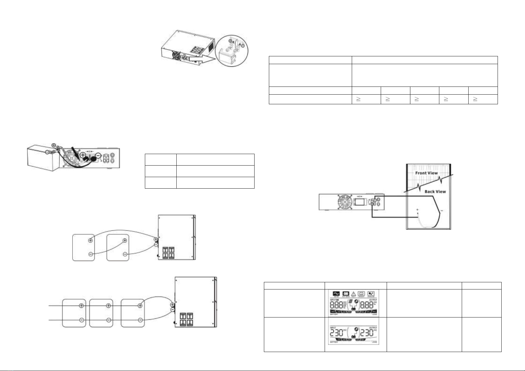
Connect External Battery
Step 1- Take away the cover of external battery terminal.
Step 2- Following battery polarity guide printed near the battery terminal!
Place the external battery cable ring terminal over the battery terminal.
RED cable to the positive terminal (+);
BLACK cable to the negative terminal (-).
WARNING! Please use the appropriate battery cable. Please refer to Important Safety
Warnings Section for the details.
Step 3- Tight the battery cables with the M5 nuts.
Do NOT place anything between the flat part of
battery terminal and the battery cable ring terminal,
or overheating may occur.
(See Fig. 1)
Step 4- Install a DC Breaker in a positive battery
line. The rating of the DC Breaker must be according
to the inverter's battery current (75 Amp). Keep the DC breaker off. (see Fig. 2)
Step 5- Connect battery cables to the external batteries. Note: For the user operation safety,
we strongly recommend that you should use tapes to isolate the battery terminals before you
start to operate the unit.
1) Single battery connection(Refer to Fig. 2): When using a single battery, its voltage
must be equal to the Nominal DC Voltage of the unit (see below Table 1).
2) Multiple batteries in series connection(Refer to Fig. 3): All batteries must be equal
in voltage and amp hour capacity. The sum of their voltages must be equal to the nominal DC
Voltage of the unit.
Fig 3
3) Multiple batteries in parallel connection(Refer to Fig. 4): Each battery's voltage
must be equal to the Nominal DC Voltage of the unit.
Fig 4
Step 6- Make sure to connect the polarity of battery side and the unit correctly.
Positive pole (Red) of battery to the positive terminal (+)of the unit.
Negative pole (Black) of battery to the negative terminal (-) of the unit.
Step 7- Put the covers back to the external battery terminals.
Step 8- Take the DC breaker on.
Connect to Solar Panel
To prevent any damage to the solar charger, please DO select the solar panel and battery
capacity according to recommended specifications below.
Solar Panel
Recommended Spec
Maximum Output Voltage
(Vm)
40 VDC for 1200VA, 60 VDC for 2400VA
*1200VA: Maximum open-circuit voltage (Voc) < 40V
2400VA: Maximum open-circuit voltage (Voc) < 60V
Maximum output current (Im)
50Amp
40Amp
30Amp
20Amp
10Amp
Suggested battery capacity
250Ah
200Ah
165Ah
135Ah
100Ah
Step 1- Connect one cable to the positive(+) pole of solar panel and solar charger positive
(+) terminal.
Step 2- Connect the other cable to the negative (-) pole of solar panel and solar charger
negative (-) terminal.
Step 3- Check the solar charging indicator. If the green LED flashes, it means that batteries
are charged by solar power. When the batteries are fully charged, the green LED will be
lighting. If there is no solar power available, the green LED will be off. If any fault occurs on
charger, the red LED will light up. (See following chart)
6. Operation
Power On/Off
Once the inverter has been properly installed, press the power switch to turn on the unit. The
unit will work automatically in line mode or inverter mode according to input utility power's
status. When press the power switch again, the unit will be turned off.
LCD Indicators & Audible Alarms
There are three indicators (Green/Red/Yellow) in the front panel of the unit.
Status
LCD
Indicator
Alarm
Power on: when the
unit is powered on, it
will enter this mode
for 3 seconds.
Three LEDs are on for few
seconds.
Off
Standby Mode:
bypass output and
charger are turned
on.
Charged by AC
Floating charging: Green
LED steady flash every 10
seconds
Constant charging mode:
Green LED quickly flashing.
Off
Fig. 2
Table 1
Model
Nominal Battery DC Voltage
1200VA
12 VDC
2400VA
24 VDC
Fig.1
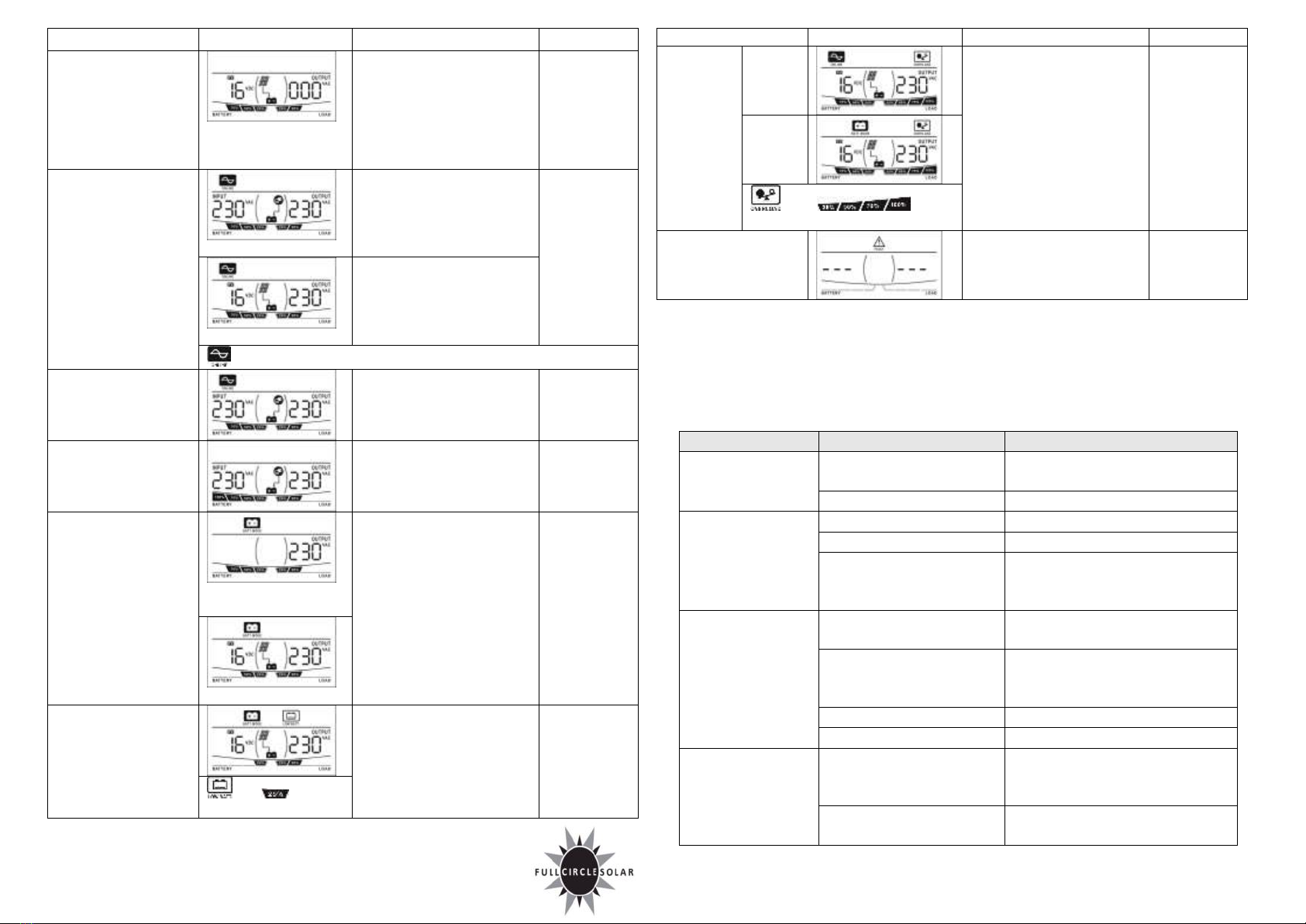
Status
LCD
Indicator
Alarm
Standby Mode:
bypass output and PV
charger are turned
on. Solar energy is
not sufficient to
supported all
connected loads.
Charged by PV
N/A
Off
Line Mode
Charged by AC
Floating charging: Green
LED on.
Constant charging mode:
Green LED flashing.
Off
Charged by PV
N/A
icon flashes when AVR is working.
Overcharging in Line
Mode
Red LED flashes every four
seconds.
Continuously
sounding
Overcharging in
Standby Mode
Red LED flashes every four
seconds.
Continuously
sounding
Battery Mode
Output power from
battery
Yellow LED on.
Off
Output power from PV
Low battery warning
Yellow LED flashes every
second.
Sounding
every second
and icons
will flash.
Status
LCD
Indicator
Alarm
Overload:
when
connected
load is
over 110%
Line
Mode
Red LED flashes every 0.5
second.
Sounding
every 0.5
second
Battery
Mode
and icons
will flash.
Fault Mode
Red LED on.
Continuously
sounding
Charging Current Selector
There are two charging current selections: 10A and 20A. Simply switch this selector according
to silk printing on the back panel.
7. Trouble Shooting
Use the table below to solve minor problems.
Problem
Possible Cause
Solutions
Utility power is
normal but the unit
is in battery mode.
AC input power cord is not
connected well.
Check AC input power connection.
Input breaker is activated.
Reset the input breaker.
When power fails,
the backup time is
shorten.
The unit is overload.
Remove some non-critical loads.
Battery voltage is too low.
Charge the unit at least 8 hours.
Battery capacity is not full
even after charge the unit for
at least 8 hours.
Check the date code of the battery. If
the batteries are too old, replace the
batteries.
No LED display on
the front panel when
the utility power is
normal.
The unit is not turned on.
Press power switch to turn on the
unit.
Battery is not connected well.
Check the external battery cable and
terminal. Make sure all the battery
connections to the unit are all correct.
Battery defect.
Replace the batteries.
Battery voltage is too low.
Charge the unit at least 8 hours.
The unit is in fault
and restart circularly.
The unit is overload.
Verify that the load matches the
capability specified in the
specification.
Output is short circuited.
Check the loads and remove loads
which cause short circuit.
If there is any abnormal situations occur, which doesn't list above, please call the service
people immediately for professional examine.
This manual suits for next models
1
Popular Inverter manuals by other brands


BARRON
BARRON EXITRONIX Tucson Micro Series installation instructions

Baumer
Baumer HUBNER TDP 0,2 Series Mounting and operating instructions

electroil
electroil ITTPD11W-RS-BC Operation and Maintenance Handbook

Silicon Solar
Silicon Solar TPS555-1230 instruction manual

Mission Critical
Mission Critical Xantrex Freedom SW-RVC owner's guide

HP
HP 3312A Operating and service manual


