Energie Solar Block ULTRA Use and care manual


www.energie.pt 3
INDICE
1. INTRODUction........................................................................................................................5
2. GeneraLITY............................................................................................................................. 5
2.1. Symbology..............................................................................................................................5
2.2. Mnufecturer’s liability ...........................................................................................................5
2.3. Installer’s Liability ..................................................................................................................6
2.4. Safety Information.................................................................................................................6
3. Indications..............................................................................................................................6
3.1. Unit inspection.......................................................................................................................6
3.2. Lodging a complaint............................................................................................................... 6
3.3. Embalagem Packaging ...........................................................................................................7
3.4. Transporting the unit.............................................................................................................7
3.5. Preparation of installation site ..............................................................................................8
3.5.1. Thermodynamic solar panel..................................................................................................8
3.5.2. Thermodynamic Solar Block..................................................................................................8
3.5.3. Unit storage...........................................................................................................................8
4. THERMODYNAMIC SOLAR BLOCK.......................................................................................... 9
4.1. Operation............................................................................................................................... 9
4.2. Components...........................................................................................................................9
5. TECHNICAL SPECIFICATIONS................................................................................................10
5.1. Solar Block 6 ULTRA .............................................................................................................10
5.2. Solar block 12 ULTRA/ ULTRA PLUS.....................................................................................11
5.3. Solar Block 16 ULTRA/ ULTRA PLUS.....................................................................................12
5.4. Solar Block 32 ULTRA........................................................................................................... 13
6. InstalaTION ..........................................................................................................................14
6.1. Installation tools required ...................................................................................................14
6.2. Thermodynamic Solar Panel................................................................................................14
6.2.1. Panel orientation.................................................................................................................14
6.2.2. Panel Inclination..................................................................................................................14
6.2.3. Distance...............................................................................................................................15
6.2.4. Unevenness.........................................................................................................................15
6.2.5. Standard Gap of the Panels.................................................................................................16
6.2.6. Direction of the panels........................................................................................................16

ASSEMBLYANDUSERMANUAL
SOLAR BLOCK ULTRA
4www.energie.pt
6.2.7. Solar panels layout..............................................................................................................17
6.2.8. Fixation................................................................................................................................18
6.3. Thermodynamic Block .........................................................................................................21
6.3.1. Installation site....................................................................................................................21
6.3.2. Dimensions..........................................................................................................................21
6.3.3. Connections SB ULTRA and SB ULTRA PLUS........................................................................22
6.3.4. Implementation of piping connections (welds)..................................................................23
6.3.5. Inlet / Outlet connection of the panels to the Solar Block.................................................24
6.3.6. Leak test ..............................................................................................................................24
6.3.7. Vacuum ...............................................................................................................................25
6.3.8. Refrigerant load ..................................................................................................................25
7. ULTRA PLUS SOLAR BLOCK (ACTIVATE DHW BACKUP RESISTANCE)...................................26
8. ULTRA SOLAR BLOCK (ACTIVATE DHW CONTROL) ..............................................................26
9. hydraulic connection ...........................................................................................................27
9.1. Hydraulic connection BS ULTRA –Central Heating.............................................................28
9.2. Hydraulic connection BS ULTRA –DHW..............................................................................28
9.3. Hydraulic connection BS ULTRA –CH+DHW.......................................................................29
9.4. Hydraulic connection BS ULTRA PLUS.................................................................................30
6.6. Electrical connections ................................................................................................................31
10. Control Panel ....................................................................................................................... 32
11. Alarm.................................................................................................................................... 38
12. Guarantee ............................................................................................................................41
Revisão 1
ASSEMBLYANDUSERMANUAL
SOLAR BLOCK ULTRA
www.energie.pt 5
1. INTRODUCTION
Esteemed Client,
Thank you and congratulations for buying an ENERGIE product, the upshot of several years of
experience in the sector.
We have built products based on specific studies, top quality materials and highly advanced
technologies.
Our company’s serious approach ensures you all the support you’ll need from the sizing stage, to
installation and assistance.
For the best use of this product, we would ask you to read this instruction manual carefully in which
you will find all the indications, information and tips you need to enjoy all the advantages that this
appliance has to offer and by following its indications and regulations in force you will be assured of
optimum operation and a perfect performance.
The information contained in this document is subject to any modifications deemed necessary to
enhance the product without any prior notice.
Our services are always at your disposal. Feel free to call upon us!
2. GENERALITY
2.1. Symbology
The notes/symbols shown can be found throughout the manual. They are intended to indicate and
draw attention to certain situations/indications. In this way we seek to ensure any possible problems
for the installer or user and assure smooth equipment performance.
Warning / Important Information.
Indicates any potentially dangerous situation which may result in physical injury or material
damage.
2.2. Mnufecturer’s liability
Our products are manufactured in line with the requirements of the various European directives.
With a constant concern for the quality and performance of our products, we make a continuous effort
to improve them. This iswhy we reserve the right to modify the information described in this document
at any time.
As the manufacturers we cease to be liable for the malfunctioning or even breakdown of the
equipment whenever:
•The usage instructions are not respected;
•The installation instructions are not respected;
•Lack of maintenance (where required).

ASSEMBLYANDUSERMANUAL
SOLAR BLOCK ULTRA
6www.energie.pt
2.3. Installer’s Liability
The installer is liable for proper equipment installation and for putting into operation. The installer
must bear in mind the following notes:
•Read and closely follow the instructions of the manuals supplied with the appliance;
•Carry out installation in accordance with standards in force and required by the manufacturer;
•Carry out the initial start-up of the equipment and verify all the checkpoints;
•Explain the installation to the user as well as how he/she should use the equipment;
•Notify the user of its obligation, where required, as regards equipment maintenance and
inspection operations;
•Obligation to provide the user with all the documentation supplied with the equipment
(manuals and warranty certificate).
2.4. Safety Information
With a view to protecting the physical integrity of the operator as well as of the equipment, it is vital
that all the safety information noted in this manual should be taken into account.
This appliance is not envisaged for use by people (including children) whose physical, sensorial or
mental capabilities are reduced or by people without any experience or knowledge, unless they have
been given supervision or instructions about use of the appliance by someone responsible for its safety.
Children must be supervised to ensure that they do not play with the appliance.
3. INDICATIONS
This manual accompanies all the “Thermodynamic Solar Block HT 12-32” equipment and contains
important instructions which must be followed during installation.
3.1. Unit inspection
The unit was tested and inspected for quality assurance before its dispatch. Carefully inspect the
equipment components (Solar Block, Solar Panels etc.) as soon as you receive it in order to check that
all the equipment is intact.
Confirm whether all the parts requested have been received in accordance with that which has been
specified and whether the type, size and voltage of the unit are correct.
3.2. Lodging a complaint
If damage is identified in the inspection carried out at the time of reception of the unit, describe the
damage in the transport reception document. Any transport complaint must be submitted at the act
of delivery.
If you are in any doubt, get in touch with ENERGIE to obtain information about how to lodge a
complaint with the haulage company.
Should damage occur during transport, do not install the unit. Keep all packaging for
inspection of the hauler.
ASSEMBLYANDUSERMANUAL
SOLAR BLOCK ULTRA
www.energie.pt 7
3.3. Embalagem Packaging
The Thermodynamic Block is packed in a bottomless cardboard box and is secured to a treated
pinewood pallet using plastic tape.
The thermodynamic solar panels are packed in cardboard boxes unless otherwise provided for.
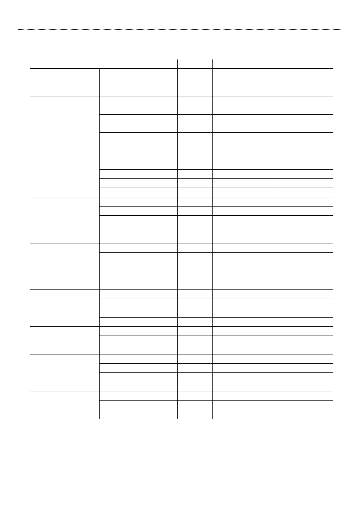
The dimensions of the boxes, pallets and respective weights for the Thermodynamic blocks are shown
in table 1
Model
Box (H*L*P mm)
Pallet (H*L*P mm)
Weight (Kg)
SB 6 ULTRA
1065x752x1002
110x750x1000
98
SB 12 ULTRA
115
SB 16 ULTRA
128
SB 32 ULTRA
135
SB 12 ULTRA PLUS
1880x752x1002
110x750x1000
230
SB 16 ULTRA PLUS
243
Table 1: Dimensions of the boxes, pallets and respective weights
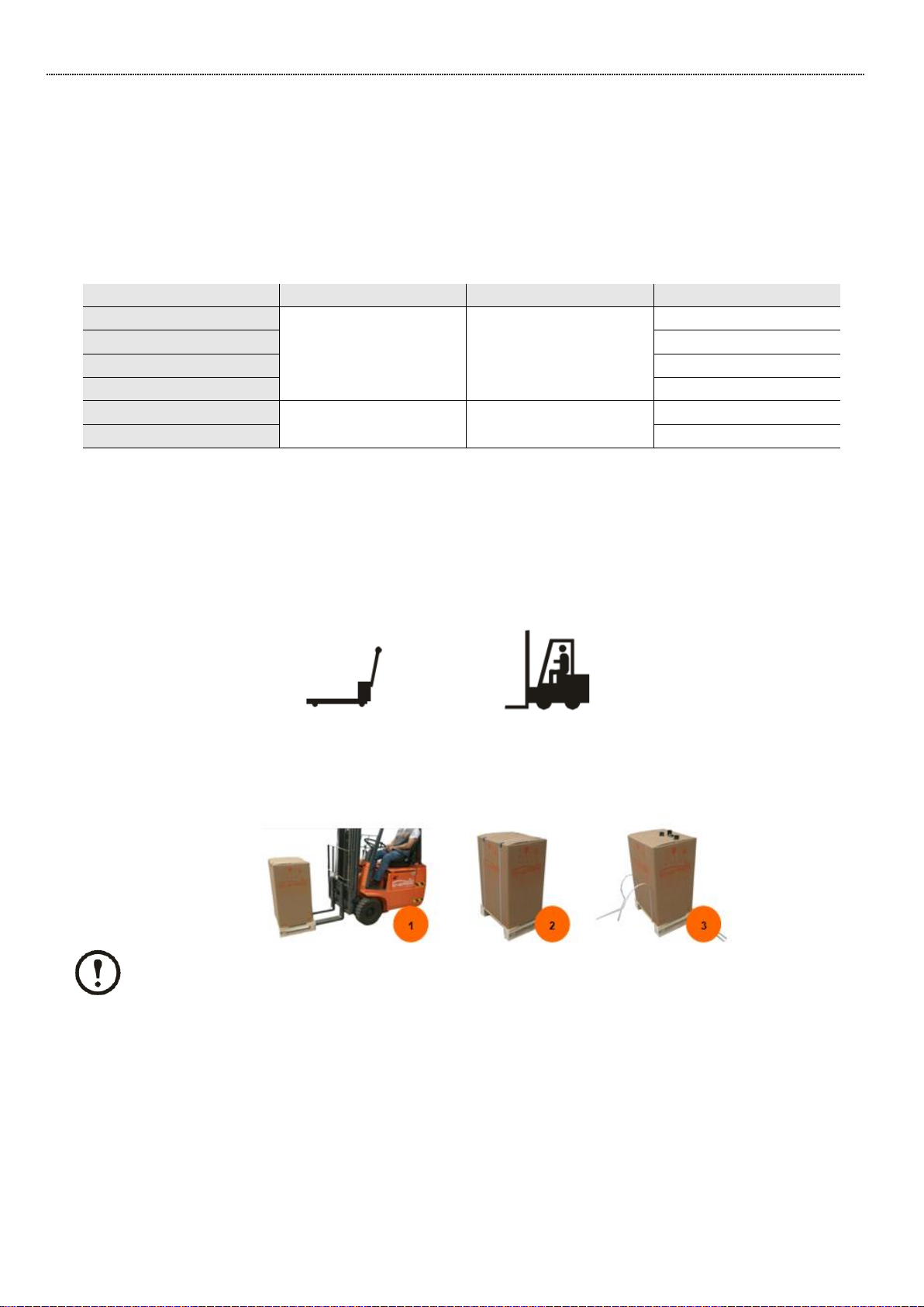
3.4. Transporting the unit
The tools recommended for transporting the unit whilst it is still in the pallet may be: forklift truck or
pallet rack. Where possible, the latter must move/transport the unit to the final destination (point of
installation).
When transporting the unit, make sure that you only lift it by its lower part and always with the unit
placed on the pallet. Do not try to move the unit without help.
It is vital to follow all the warnings and recommendations stated on the packaging boxes..
Pallets truck
Lift truck
ASSEMBLYANDUSERMANUAL
SOLAR BLOCK ULTRA
8www.energie.pt
3.5. Preparation of installation site
3.5.1. Thermodynamic solar panel
The nature of the site and the inclination angle where the panels are installed are important factors to
bear in mind in installation.
To capture the maximum incident solar radiation, the panels must have an inclination of between 10º
- 90º with regard to the horizontal and be oriented Southwards. In addition to the factors mentioned
above the panels must be at ventilated places and preferably not be exposed to any kind of shade.
It is incumbent upon the installer to comply with all the requirements demanded by ENERGIE
and adapt the method for securing the panels in line with the site.
If the panels are subject to adverse atmospheric conditions, in the main strong gusts of wind,
it is the responsibility of the installer to strengthen the panel affixation structure.
3.5.2. Thermodynamic Solar Block
The Block installation site must be carefully designed. And before carrying out any procedure you must
bear in mind:
•Easy access and sufficient space to move the equipment as far as the installation site;
•Load capacity of the ground (verify the weight of the equipment);
•Leave point for the hydraulic and electrical connections;
•The base of the site where the equipment will be placed must be perfectly even;
•Consider minimum distances with regard to walls, ceilings or any other type of obstacles which
may make access difficult, both at the installation as well as in any maintenance operation.
3.5.3. Unit storage
If the unit is not installed immediately, keep it in a safe place protected from the weather in such a way
that it does not suffer any kind of damage which may hinder its correct operation.
Poor installation of the unit may give rise to the cancellation of the manufacturer’s warranty.
ASSEMBLYANDUSERMANUAL
SOLAR BLOCK ULTRA
www.energie.pt 9
4. THERMODYNAMIC SOLAR BLOCK
4.1. Operation
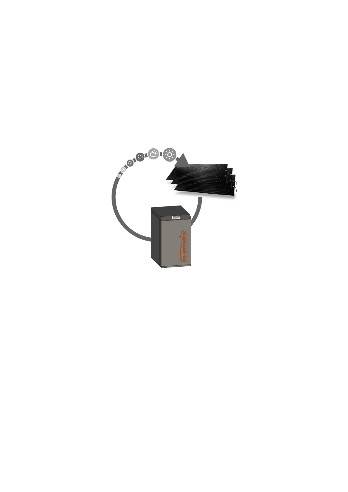
ENERGIE Thermodynamic Solar Blocks ULTRA are items of equipment intended for climatization:
atmosphere, industrial applications etc.
The thermodynamic panel is placed on the exterior and it ensures the capturing of energy as regards:
•Direct and diffuse radiation;
•Outside air by natural convection;
•Wind effect (almost always to be found);
•Rainwater
The temperature difference brought about by the previous factors ensures that the fluid will change
to vapour state inside the panel.
The compressor aspirates the refrigerant fluid (vapour) of the panel, raising the pressure and
temperature thereof, which is transmitted to the water circuit by way of a heat exchanger.
The heat exchanger is located inside the thermodynamic group (Solar Block), providing heat to the
water.
When the refrigerant fluid reaches the expansion valve it is at its liquid phase and the load loss owing
to strangulation reduces the pressure and the fluid is re-prepared for entry into the panels.
4.2. Components
The Thermodynamic Group is made up of two components:
a) Thermodynamic Group;
b) Thermodynamic solar panels
The solar panel is a plate made of twin-channel pressed aluminium with post-pressing anodic oxidation.
The panel has the dimensions 2000 mm x 800 mm x 20 mm and it has a fluid flow entry and exit in a
copper-aluminium tube with an interior diameter of ¼’’

ASSEMBLYANDUSERMANUAL
SOLAR BLOCK ULTRA
10 www.energie.pt
5. TECHNICAL SPECIFICATIONS
5.1. Solar Block 6 ULTRA
Unid.
Description
Description
Model
---
---
SB 6 ULTRA
SB 6 ULTRA PLUS
Heating capacity (1)
Heating range
3,5 –10,2
Max. heating capacity
10,2
Heating capacity (2)
Nominal heating capacity
kW
8,5
Nominal power
consuption
kW
1,71
COP
---
4,97
DHW (3)
Load profile
---
---
L
water heating energy
efficiency
%
---
146
Energy efficiency class
---
---
A+
AEC
kWh/a
---
701
COP
---
---
3,44
Electrical data
Main power
V~
230~
Max power
kW
2,75
Frequency
Hz
50/ 60
Compressor
Typology
---
Twin Rotary / Inverter
Number
---
1
Evaporator
(Thermodynamic
solar panel)
Number
---
6
Material
---
Aluminum
surfece
m²
9,6
Refrigerante
Type
---
R410A
Min load
Kg
1,9
Hydraulic circuit
Nominal flow
m3/h
1,7
Nº of pumps
---
1
Typology
---
EC
Max power consuption
W
60
DHW tank
Volume
L
---
200
Material
---
---
AISI 316
Backup electrical heater
W
---
1500
Hydraulic
connections
Water outlet
inches
1”
1”
Water inlet
inches
1”
1”
DHW input
inches
---
¾”
DHW output
inches
---
¾”
Sound (4)
Internal unit
db(A)
55
Evaporator
db(A)
13
Weight
Without pallet
Kg
115
208
(1) Acording EN14511; Air temperature DB/WB 7°C/6°C; Water temperature inlet 30°C/ outlet35°C; Solar
radiation 400w/m²;
(2) Acording EN14511; Air temperature DB/WB 14°C/13°C; Water temperature inlet 30°C/ outlet35°C;
Solar radiation 800w/m²;
(3) According EN 16147, A 14 / W 10-54
(4) Distance from unit 10m;
ASSEMBLYANDUSERMANUAL
SOLAR BLOCK ULTRA
www.energie.pt 11
5.2. Solar block 12 ULTRA/ ULTRA PLUS
Unid.
Descrição
Descrição
Model
---
---
BS12 ULTRA
BS12 ULTRA PLUS
Heating capacity (1)
Heating range
5 - 19
Max. heating capacity
18,7
Heating capacity (2)
Nominal heating
capacity
kW
10,3
Nominal power
consuption
kW
2,15
COP
---
4,8
DHW (3)
Load profile
---
---
L
water heating energy
efficiency
%
---
143
Energy efficiency class
---
---
A+
AEC
kWh/a
---
714
COP
---
---
3,38
Electrical data
Main power
V~
230 | 400
Max power
kW
5,7
Frequency
Hz
50/ 60
Compressor
Typology
---
Twin Rotary / Inverter
Number
---
1
Evaporator
(Thermodynamic
solar panel)
Number
---
12
Material
---
Aluminum
surfece
m²
19,2
Refrigerante
Type
---
R410A
Min load
Kg
3,5
Hydraulic circuit
Nominal flow
m3/h
1,6
Nº of pumps
---
1
Typology
---
EC
Max power consuption
W
60
DHW tank
Volume
L
---
200
Material
---
---
AISI 316
Backup electrical heater
W
---
1500
Hydraulic
connections
Water outlet
inches
1”
1”
Water inlet
inches
1”
1”
DHW input
inches
---
¾”
DHW output
inches
---
¾”
Sound (4)
Internal unit
db(A)
61
Evaporator
db(A)
13
Weight
Without pallet
Kg
115
230
(1) Acording EN14511; Air temperature DB/WB 7°C/6°C; Water temperature inlet 30°C/ outlet35°C; Solar
radiation 400w/m²;
(2) Acording EN14511; Air temperature DB/WB 14°C/13°C; Water temperature inlet 30°C/ outlet35°C;
Solar radiation 800w/m²;
(3) According EN 16147, A 14 / W 10-54
(4) Distance from unit 10m;

ASSEMBLYANDUSERMANUAL
SOLAR BLOCK ULTRA
12 www.energie.pt
5.3. Solar Block 16 ULTRA/ ULTRA PLUS
Unid.
Descrição
Descrição
Model
---
---
BS16 ULTRA
BS16 ULTRA PLUS
Heating capacity (1)
Heating range
8-26
Max. heating capacity
26,8
Heating capacity (2)
Nominal heating
capacity
kW
16,2
Nominal power
consuption
kW
3,47
COP
---
4,7
DHW (3)
Load profile
---
---
L
water heating energy
efficiency
%
---
142
Energy efficiency class
---
---
A+
AEC
kWh/a
---
719
COP
---
---
3,33
Electrical data
Main power
V~
400
Max power
kW
7,8
Frequency
Hz
50/ 60
Compressor
Typology
---
Twin Rotary / Inverter
Number
---
1
Evaporator
(Thermodynamic
solar panel)
Number
---
16
Material
---
Aluminum
surfece
m²
25,6
Refrigerante
Type
---
R410A
Min load
Kg
4,5
Hydraulic circuit
Nominal flow
m3/h
2,8
Nº of pumps
---
1
Typology
---
EC
Max power consuption
W
60
DHW tank
Volume
L
---
200
Material
---
---
AISI 316
Backup electrical heater
W
---
1500
Hydraulic
connections
Water outlet
inches
1”
1”
Water inlet
inches
1”
1”
DHW input
inches
---
¾”
DHW output
inches
---
¾”
Sound (4)
Internal unit
db(A)
62
Evaporator
db(A)
13
Weight
Without pallet
Kg
128
243
(1) Acording EN14511; Air temperature DB/WB 7°C/6°C; Water temperature inlet 30°C/ outlet35°C; Solar
radiation 400w/m²;
(2) Acording EN14511; Air temperature DB/WB 14°C/13°C; Water temperature inlet 30°C/ outlet35°C;
Solar radiation 800w/m²;
(3) According EN 16147, A 14 / W 10-54
(4) Distance from unit 10m;

ASSEMBLYANDUSERMANUAL
SOLAR BLOCK ULTRA
www.energie.pt 13
5.4. Solar Block 32 ULTRA
Unid.
Descrição
Model
---
---
BS 32 ULTRA
Heating capacity (1)
Heating range
18,5 –48,2
Max. heating capacity
48,2
Heating capacity (2)
Nominal heating capacity
kW
39,6
Nominal power consuption
kW
8,1
COP
---
4,91
Electrical data
Main power
V
3N~/ 400V
Max power
kW
13,2
Frequency
Hz
50/ 60
Compressor
Typology
---
Twin Rotary/ inverter
Number
---
1
Evaporator
(Thermodynamic
solar panel)
Number
---
32
Material
---
Aluminum
Surface
m²
51,2
Refrigerante
Type
---
R410A
Min load
Kg
7
Hydraulic circuit
Nominal flow
m3/h
6,5
Nº of pumps
---
1
Typology
---
EC
Max power consuption
W
80
Hydraulic
connections
Water outlet
inches
1” ¼
Water inlet
inches
1” ¼
Sound (4)
Internal unit
db(A)
55
Evaporator
db(A)
13
Weight
Without pallet
Kg
135
(1) Acording EN14511; Air temperature DB/WB 7°C/6°C; Water temperature inlet 30°C/ outlet35°C; Solar
radiation 400w/m²;
(2) Acording EN14511; Air temperature DB/WB 14°C/13°C; Water temperature inlet 30°C/ outlet35°C;
Solar radiation 800w/m²;
(3) Distance from unit 10m;
ASSEMBLYANDUSERMANUAL
SOLAR BLOCK ULTRA
14 www.energie.pt
6. INSTALATION
6.1. Installation tools required
To ensure correct assembly of the equipment, the installing technician must be endowed with the
following tools:
Manometers (low and high pressure)
Refrigerant gas cylinder
Vacuum pump
Blowpipe (welding)
Refrigerant gas loading station or scales
Copper rods with 40% of silver
Pipe cutter; Tube bender; Tube expander
Descaler
Screwdriver; Rotoblock wrench
Adjustable spanner
Measuring tape
Set of hydrant keys or ratchet
To verify the operationality of the equipment the installing technician must have at its disposal:
•Multimeter;
•Appliance for measuring temperature;
•EVD display
6.2. Thermodynamic Solar Panel
6.2.1. Panel orientation
ENERGIE panels must preferably be oriented in a southerly direction, but they may also have an
orientation towards Northeast and Northwest.
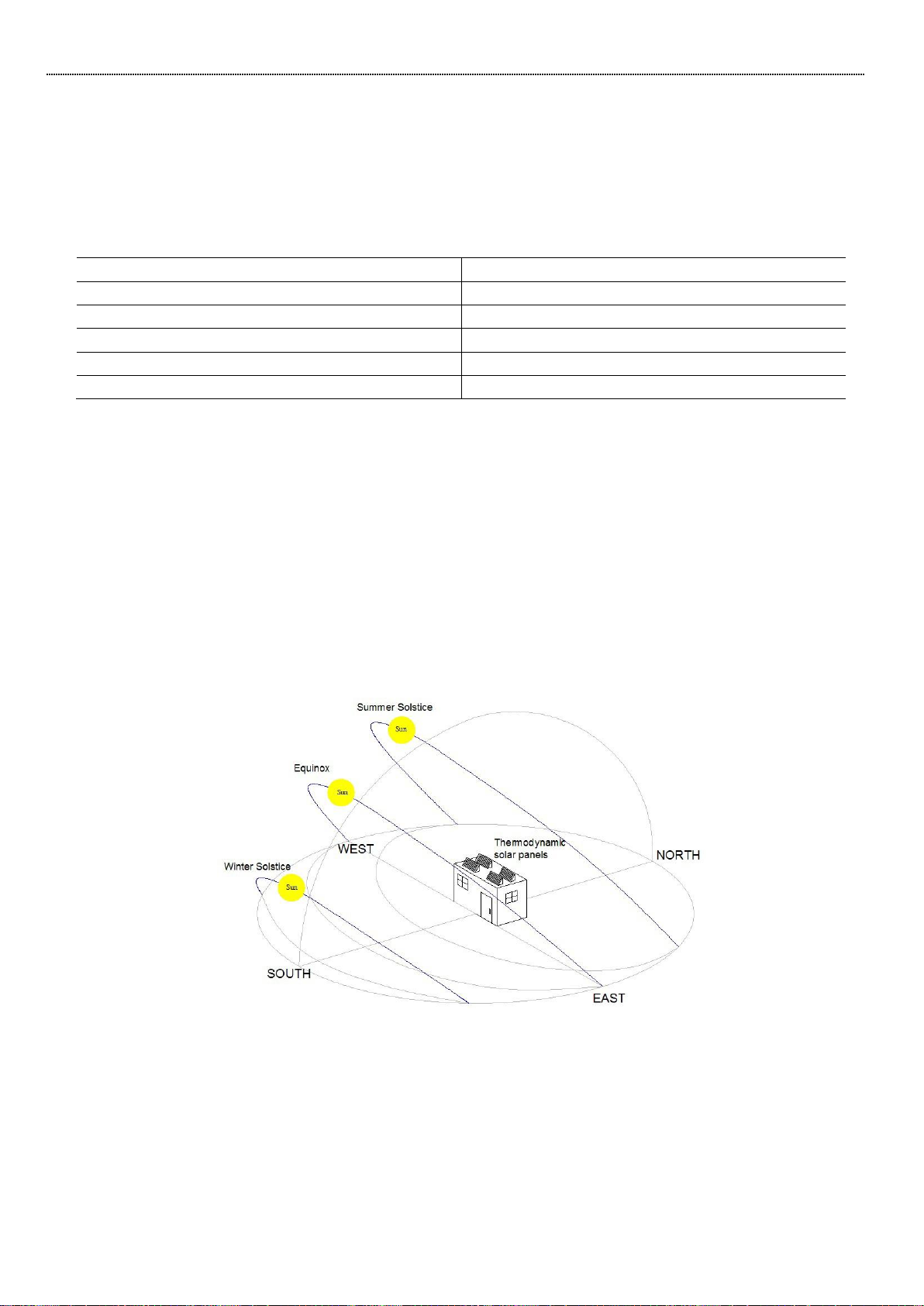
6.2.2. Panel Inclination
The inclination angle of the sun rays with regard to the horizontal varies in accordance with the seasons
of the year. In Winter, at the Zenith, the solar rays form an angle of 20º to 40º with regard to the
horizon. In Summer the angle is between 60º and 80º.
To get the most out of the solar rays on the panel, it’s best to choose an inclination between 45º and
90º.

ASSEMBLYANDUSERMANUAL
SOLAR BLOCK ULTRA
www.energie.pt 15
However, you may install the panels with another inclination in certain situations.
6.2.3. Distance
The maximum distance between the panels and the Thermodynamic Block depends on certain factors
such as the equipment model, the no. of curves, the piping diameter etc.
However, we would recommend that the distance should not exceed the following values:
•Solar block 6 and 12 → 15m;
•Solar block 16 → 20m;
•Solar block 32 →30m.
For Installations with a distance greater than those indicated must contact the Technical Dept.
6.2.4. Unevenness
Under normal circunstances the total maximum gradient must always be less than 15 mts.
However, there are situations where it is not possible to respect these distances, in these cases you
must consult our technical department.
The aspiration piping must rise above the level of the panels, in the same way as the distribution shaft
in order to avoid the rapid siphon effect of the liquid when the compressor stops.
Legend:
A
Solar panel
B
Distributor
C
SB ULTRA / SB ULTRA PLUS
A
B
C
ASSEMBLYANDUSERMANUAL
SOLAR BLOCK ULTRA
16 www.energie.pt
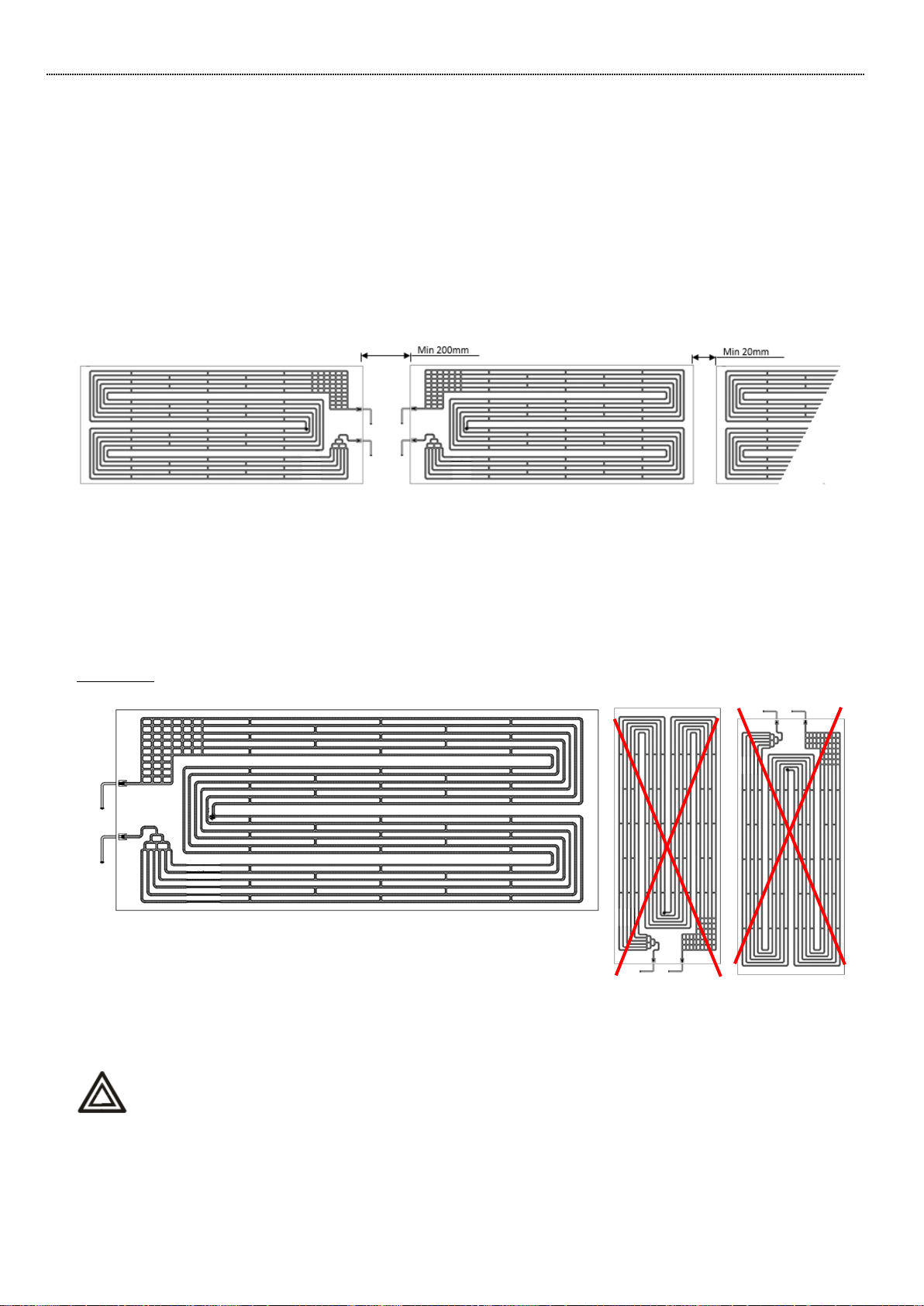
6.2.5. Standard Gap of the Panels
The position of the panels and the choice of the sides of the connections must be carried out so as to
limit the length of the piping and simplify the connections.
The panel gap is determined so as to facilitate its placement and the implementation of the
connections between piping, though due consideration must be given to:
•Minimum space between the panels on the connections’ side: 200mm (ideal space: 500mm);
•Space between the panels on the side opposite the connections: they should preferably not be
completely stuck together (preferably> 20mm).
6.2.6. Direction of the panels
The direction of the panels is defined by the outlets of the tubes pointing downwards and by the view
of the front part of the panel. They must always be placed with the largest length horizontally and the
connections pointing downwards. In this context two panel models are manufactured:
Left panel
A –Liquid line (input)
B –Vapor line (output)
A left-hand panel is installed on the right (front view). To this end, it has connections on the left side.
The Solar panel must not be installed on the vertical in accordance with the
representation indicated above with a red cross.
A
B

ASSEMBLYANDUSERMANUAL
SOLAR BLOCK ULTRA
www.energie.pt 17
Right panel
A –Liquid line (input)
B –Vapor line (output)
A right-hand panel is installed on the left-hand side (front view). To this end, it has connections on
right- hand side.
The Solar panel must not be installed on the vertical in accordance with the
representation indicated above with a red cross.
6.2.7. Solar panels layout
The relative position of the panels depends on the system to be installed, the availability of the
installation area, the architectonic integration etc.
In the diagrams below some of the possible positioning layouts of the panels are represented.
However, you may consult the annex for complementary information about the position of the panels
in the installation.
Example: Solar Block 12 Ultra
A
B
ASSEMBLYANDUSERMANUAL
SOLAR BLOCK ULTRA
18 www.energie.pt
In the event of some other positioning of the panels, you must contact our Technical
Department.
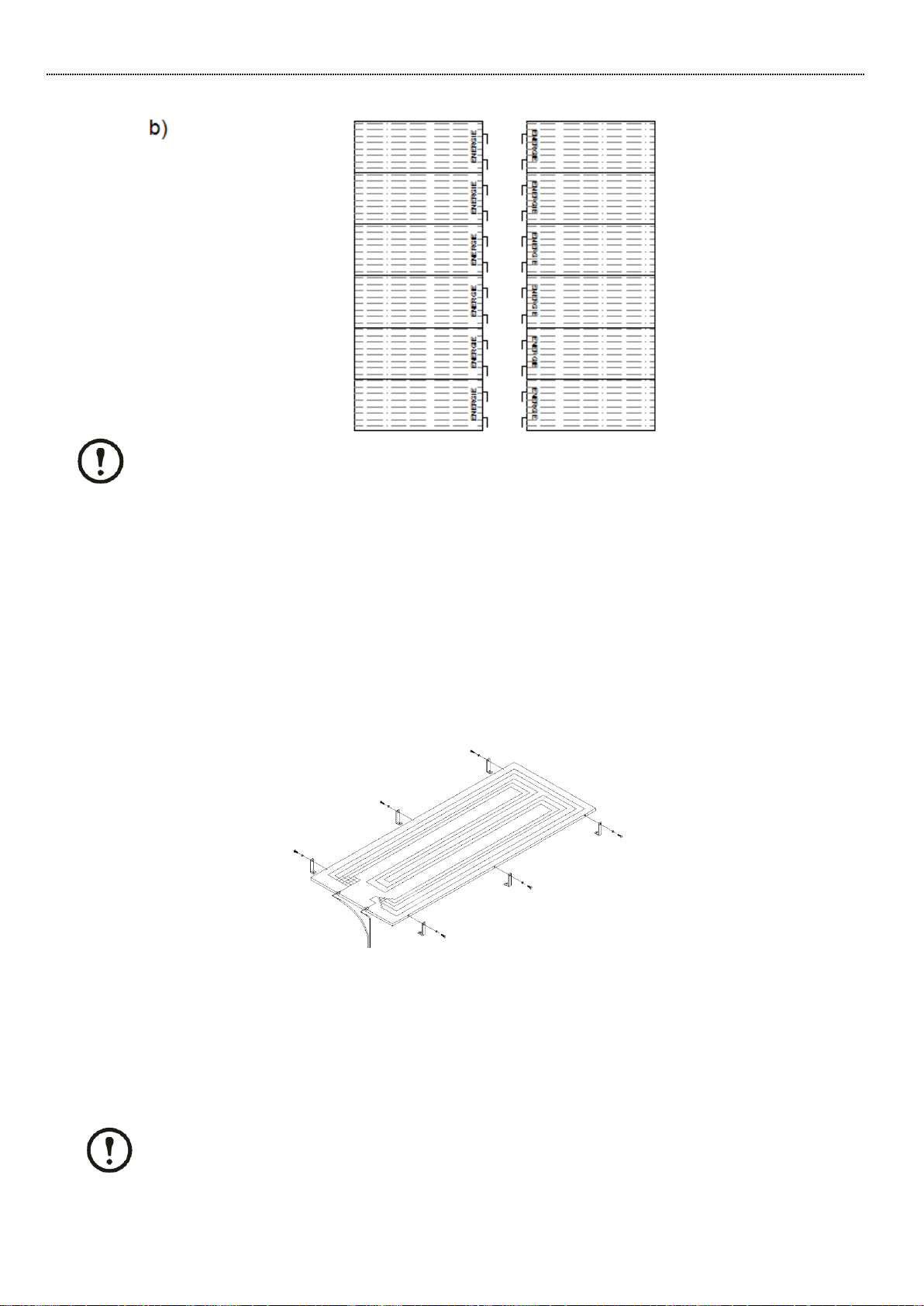
6.2.8. Fixation
The affixation of panels depends on the installation site and the method and type of affixation is the
installer’s decision. However, you must bear various factors in mind (described above such as, for
example, distance, orientation…).
For a correct affixation of the panels, as regards the physical part of the affixation supports they must
have a sturdy structure in line with the circumstances of the site. Each panel must be secured at 6
points (as a minimum).
The image below illustrates an example of the fixation used:
The fixation of the panels is ensured by aluminium brackets*. The support is bent in “L” shape with two
M8 through holes. The bracket base is secured to the roof (where applicable) using an M6 screw and a
plastic plug or a female thread (depending on the situation).
The other support rib is secured to the panel by way of galvanised M6 screws to prevent corrosion
situations.
* The aluminium brackets are not supplied with the SB
The Panels must have a minimum gap of 50cm (from the previous and/or subsequent
panel)

ASSEMBLYANDUSERMANUAL
SOLAR BLOCK ULTRA
www.energie.pt 19
If the panels are subject to adverse atmospheric conditions as, strong gusts of windn, snow,
etc. it is the responsibility of the installer to strengthen the panel affixation structure.
6.2.9. Liquid Distributor and Collector, placement and connection
To ensure that the fluid reach the panels in homogeneous fashion, a liquid distributor must be installed.
This same distributor includes as many distribution tubes as there are panels in the installation.
The distributor is placed between the panels. The connection tubes to the panels must have strictly
the same length and their ends connect directly to the panels.
The distributor and the collector may be placed before the installation of the panels for the sake of
convenience (obstruction, passage of distribution tubes behind the panels).
Only remove the tube protection cover at the time of connection to the power and aspiration shafts
with a view to avoiding the penetration of impurities.
Install the distributor (s) vertically, face downwards (never horizontally!), thereby ensuring that the
fluid reaches the panels in homogeneous fashion.
If a shaft is too long for the length required, it must be rolled up and never cut.
If it is wished to shorten or elongate, this operation must be carried out on all the shafts with the same
diameter.
All ø ¼” shafts must be welded to the lower connections of the panels (liquid inlet). The shafts of the
main distributor must be welded to the secondary distributors.
It is vital that the power shafts (Ø 1/4’’) should have the same length and the same is true of
the main distributor shafts

ASSEMBLYANDUSERMANUAL
SOLAR BLOCK ULTRA
20 www.energie.pt
Depending on the Thermodynamic Block model and the position of the panels, one or more aspiration
collectors must be carried out.
The aspiration which allows the collection of the refrigerant fluid in its gaseous state must regroup all
the panel aspiration outlets (∅3/8’’) as far as the collector. This is shown in the figure below.
All the shafts must be welded to the upper panel outlets.
It is important for the connections at the collectors to be as simple as possible, respecting the
instructions in the event of any unevenness.
It is essential for the copper tubes used to be refrigerant type CUDHP according to the ISO1337 and/or
according to EN12735, both on the aspiration line and on the liquid line (power).
It is also recommended for all the piping to have good quality thermal insulation in order to avoid any
possible condensation.
The piping diameters vary with the system model as can be seen in the table below.
Modelo
Vapor line
Liquid line
Solar Block 6 ULTRA
3/4"
1/2"
Solar Block 12 ULTRA / PLUS
3/4’’
1/2’’
Solar Block 16 ULTRA / PLUS
7/8’’
3/4’’
Solar Block 32 ULTRA
1” 3/8
7/8”
This manual suits for next models
7
Table of contents
Other Energie Inverter manuals


