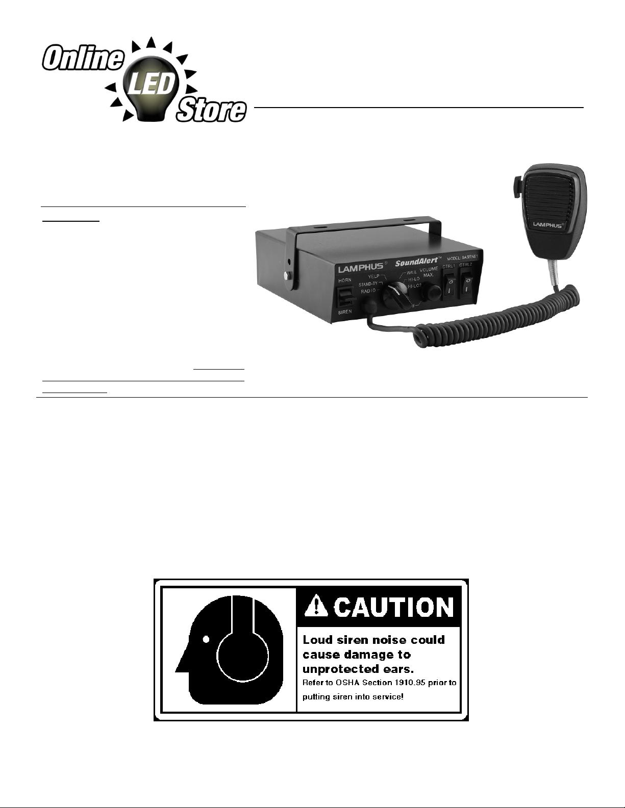
Siren w/ PTT Mic. 1
Bail Strap Bracket 1
Wiring Bundle 1
Wiring for Horn/Radio 1
Microphone Clip 1
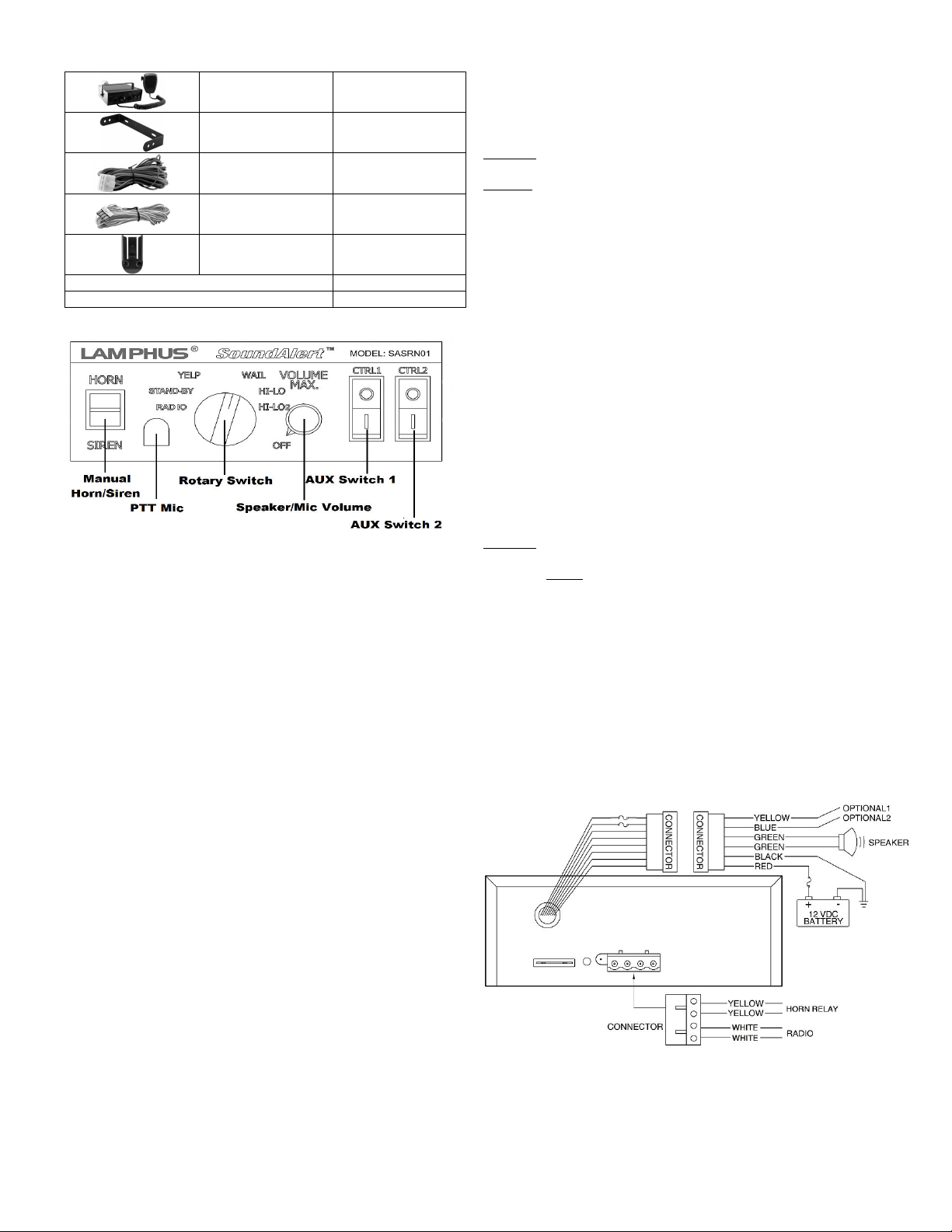
Front Panel:
Functions:
Manual Horn/Siren
This switch has two positions. Down – Siren & Up – Horn. The siren and horn
warning tone could be activated manually by engaging the switch to the positions.
Horn function can also be activated with the vehicle horn relay by connecting the
horn/radio wire of the siren unit to the horn relay of the automobile. (see wiring
diagram
PTT Mic
Push to talk microphone which overrides any activated warning tone when in use.
otary Switch
The rotary knob controls siren functions. There are 5 positions that may be
selected. (see switch functions below for detail
Speaker/Mic Volume
The volume knob controls the volume of siren and public address function. Rotating
the knob clockwise will increase the volume. Rotating the knob counter-clockwise
will decrease the volume. Rotating the knob to minimal volume will disable all siren
functions.
Aux Switch 1 & 2
The auxiliary switches are meant to be used to power other equipment on the
vehicle. Each auxiliary switch is fused with a 20 amp AGC fuse.
Switch Functions:
adio
With the rotary knob set to this function, the radio function would be activated. Any
signal that is received by the vehicle’s two-way radio will be broadcasted over the
connected speaker. (the siren must be connected to the two-way radio as outlined
in wiring section of this manual
Stand-by
With the rotary knob set to this function, the siren will be in stand-by. Manual
Horn/Siren and PTT Mic functions are enabled during stand-by.
Yelp
With the rotary knob set to this function, the yelp siren warning tone will be activated.
Wail
With the rotary knob set to this function, the wail siren warning tone will be activated.
Hi-Lo
With the rotary knob set to this function, the hi-lo siren warning tone will be activated.
Hi-Lo 2
With the rotary knob set to this function, the hi-lo 2 siren warning tone will be
activated.
The siren is designed to be mounted directly onto the dash or any other surface
around the driver’s vicinity using the included bail-strap mounting bracket. The
siren unit can also be mounted into the vehicle’s console when vehicle is
equipped with such a compartment.
WA NING! Make sure NOT to mount the siren in the deployment of any air bag.
efer to the air bag warning on the first page of this manual.
CAUTION! Permanent mounting of this product will require drilling. It is
absolutely necessary to make sure that no other vehicle components could be
damaged by this process. Check both sides of the mounting surface before
starting. If damage is likely, select a different mounting location.
Bail-strap mount:
1. Position the bail strap against the desired mounting location.
2. Scribe the area where the mounting holes would be drilled.
3. Proceed to drilling of the surface for the mounting screws. Make sure no
vehicle component could be damaged during this process.
4. Secure the bail strap to the mounting surface with the included screws.
5. Secure the siren unit to the bail strap using the included screws and washer.
Refer to mounting diagram.
Microphone Clip:
1. Position the microphone clip against the desired mounting location.
2. Make sure there microphone clip is not placed too far away from where the
siren unit will be mounted.
3. Scribe the area where the mounting holes would be drilled.
4. Proceed to drilling of the surface for the mounting screw. Make sure no
vehicle component could be damaged during this process.
5. Secure the microphone clip to the mounting surface with the included screws.
Wiring:
WA NING! All customer supplied wires that connect to the positive terminal of
the battery must be sized to supply at least 125% of the maximum operating
current and FUSED at the battery to carry that load. DO NOT USE CI CUIT
B EAKE S WITH THIS P ODUCT!
ED – To 12/24V Power Source BLACK – To Chassis Ground
YELLOW – To optional equipment 1 BLUE – To optional equipment 2
G EEN 1 – To speaker G EEN 2 – To speaker
Optional Connections:
Horn Connector (yellow – Connect the unit in-line between the horn button and horn relay
with the outer yellow wire connected to the horn button, and the inner yellow wire
connected to the horn relay.
Radio Connector (white – Connect the unit in-line between one of the radio’s output wire.
The unit will broadcast the radio in mono sound type. Should only be spliced into one of
the output wires (left or right .
Wiring Diagram:
Specifications
:
Input Voltage: 12/24 VDC +/- 20%
Input Current: 12 AMSP Max.
Input Fuse: 15 AMPS
Speaker Impedance: 8 OHMS Min.
Output Power: @ 12 VDC @ 8 OHMS 100 WATTS Max.
Online LED Store S2B Inc. ©2015 All Rights Reserved