Online UPS Specialist Pty Ltd PP1KL User manual

Online UPS PP1-15KL
User Manual

- i -
Contents
CONTENTS............................................................................................................ I
1BRIEF INTRODUCTION.............................................................................1
1.1 PROLEGOMENON ......................................................................................1
1.2 FIVE DESIGN POINTS .................................................................................1
1.3 NOTE ........................................................................................................1
2CONFIGURATION AND FUNCTION .......................................................3
2.1 FRONT PANEL ...........................................................................................3
2.2 APPEARANCE............................................................................................5
3PLACEMENT NOTES..................................................................................6
3.1 TRANSIT OR MOVE....................................................................................6
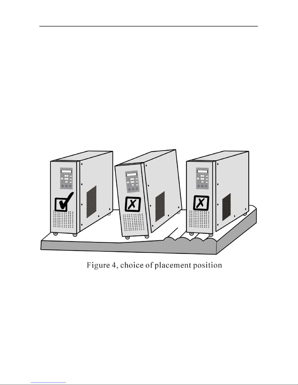
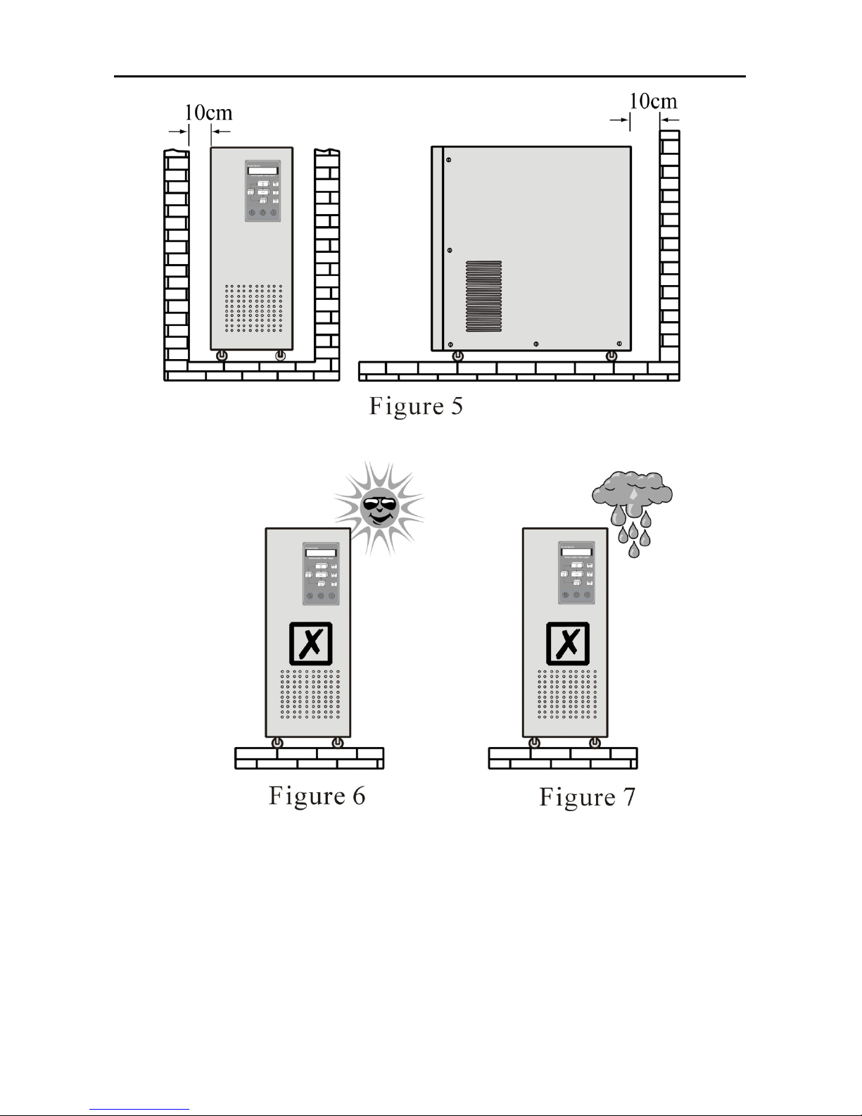
3.2 PLACEMENT .............................................................................................6
4INSTALLATION ...........................................................................................9
4.1 INPUT .......................................................................................................9
4.2 OUTPUT ..................................................................................................13
5OPERATION PROCESS ............................................................................16
5.1 PREPARE BEFORE START-UP.....................................................................16
5.2 OPERATION PROCESS FOR FIRST START-UP ..............................................16
5.3 OPERATION PROCESS FOR ROUTINE TURN-OFF ........................................18
5.4 OPERATION PROCESS FOR LONG-TIME NO SWITCH ON/OFF ......................18
6STATUS HANDLING..................................................................................19
6.1 SYMBOL SIGNIFICATION ..........................................................................19
6.2 UPS RUN STATUS INDICATION AND HANDLING WAYS WHEN NORMAL......19
7MOVEMENT HANDLING ........................................................................28
7.1 UPS SYSTEM CONFIGURATION BLOCK FIGURE:FIGURE 32 .....................28

- ii -
7.2 UPS RUNNING WAY WHEN UPS RUNS NORMALLY...................................28
7.3 UPS RUNNING WAY WHEN UTILITY DISCONNECTED ................................29
7.4 UPS RUNNING WAY WHEN UPS RUNS ON BYPASS MODE .........................29
7.5 BATTERY AND CHARGE ...........................................................................30
7.6 DAILY MAINTENANCE .............................................................................31
8COMMUNICATION INTERFACE...........................................................32
9SPECIFICATION ........................................................................................34
10 SHIPPING LIST ..........................................................................................36

- 1 -
1BRIEF INTRODUCTION
1.1 Prolegomenon
The product is designed specially aiming at the requirement of MINI
and MICRO level computer with exquisite quality and excellent function,
easy to operate. With the development of customer office automatism and
computerism, considering the bulk and the position of positing space, the
noise disturbance to personnel in office, the light, thin, short and small
product is our design direction, and we stress low noise. So this product is
optimum supply power partner for office and makes you can attain optimal
clean power quality.
1.2 Five design points
1. Small bulk and no occupation space
2. Light weight and convenience to transit
3. Beauty and nature, easy to install
4. Convenient to maintain and easy to operate
5. Package material with environment protection and no pollution to
environment
1.3 Note
The manual makes you can operate and maintain the system easily. To
normally exert all functions of the system, please note the following:
1. Read the manual carefully before use
2. Perform the operation strictly according to operating process
3. Place the equipment carefully and lightly when moving the
equipment
4. Install the power according to illumination in the manual
5. Please do not open the cover to avoid injury caused by electrical
shock
6. Please charge batteries once every a period if no used for long time

- 2 -
7. Do not use UPS on the condition of overload to avoid UPS fault
8. Please carefully keep the manual for the future reference
9. Please handle the system according to “ABNORMITY HANDLING
PROCESS” if there presents any abnormal phenomenon in machine.
10. Please keep UPS neatness and cleanness

- 3 -
2CONFIGURATION AND FUNCTION
2.1 Front panel
1) Welcome screen
WELCOME TO
×××××××××
2) Display of system status
×××××
××KVA.
3) Display of input voltage value*
ON LINE
AC IN:220V
4) Display of input frequency value*
ON LINE
AC FRE:50Hz

- 4 -
5) Display of output voltage value*
ON LINE
OUTPUT:220V
6) Display of output frequency value
ON LINE
OUT FRE:50Hz
7) Display of output power Percent
ON LINE
LOAD:80%
8) Display of battery voltage value
ON LINE
BATTERY:218V
9) Temperature display in machine
ON LINE
TEMP:33℃
Note:ON BYPASS mode,the output voltage and frequency are
displayed be “0” .LED would display only after the unit is
switched on.
*These parameters vary with machine model.
10) LCD cycle display switch button: digital signal display items
switch button.
11) UPS switch button: UPS general switch button.
(1) Turn on UPS inverter by pressing the “ON” key. UPS
convert to UPS inverter power output 20s later, UPS pure
AC output power is supplied by UPS internal power
supply equipment.
(2) By keeping pressing the OFF switch for 3s,we can shut
down the inverter,turn the UPS to bypass mode.
The button acts as general switch mainly.

- 5 -
2.2 Appearance
Figure 2 Front panel Figure 3 Rear panel
①Emission heat ventilation hole:
The ventilation hole and other small long elliptic ventilation holes
should be kept good ventilation.
② Wiring inlet/outlet hole:
Wiring inlet/outlet hole of input, output and battery pack.
③ RS232 communication interface receptacle
Standard communication interface between UPS and computer.
④ Power switch:
Power switch controls input, output and battery power switch at the
same time.
⑤ Wiring Terminal support
Power wiring Terminal support of input, output and battery.
⑥Dry contact.
⑦Maintenance switch.
⑧SNMP card.

- 6 -
3PLACEMENT NOTES
3.1 Transit or move
1. Please dismantle all barge connection firstly. (First turn off before
performing)
2. Place lightly and carefully, forbid to hit.
3. Please do not move UPS inverted.
3.2 Placement
1. Do not place the UPS on the slope or scraggy land. (Figure 4)
2. Please place the UPS in the place where keeps good ventilation, rear
panel of UPS and two side faces should keep more than 10cm away
from the wall. (Figure 5)
3. Do not install UPS under sunlight, drain and damp place. (Figure 6,
7)

- 7 -
4. Please keep away from fire source and high temperature to avoid
over-high temperature. (Figure 8)
5. Do not lay goods on the UPS. (Figure 9)
6. Do not install UPS in the place where contains caustic gas. (Figure 10)
7. Running environment temperature: 0℃-40℃.

- 8 -

- 9 -
4INSTALLATION
4.1 Input
1. Prohibit using general household socket, because the Max. current of
general socket is 15A, the socket may be burned down because of
overload.
2. Please connect UPS input terminal to utility power in nearby
switchboard. Figure 11.
Note: Don’t make anti-connection of polarity

- 10 -
3. Position and way of connect
(1) Remove two screws with “+” screw-driver (Figure 12)
(2) Open the back panel and inspect the wiring terminal below the
power switch. (Figure 13)
4. Relock the special cover after completing connection.
5. Please first fetch in the power cables of input, output and batteries
pack through inlet/outlet hole of distribution electricity and then barge
connect to terminal plate.
Figure 12

- 11 -

- 12 -
6. Please connect power correctly
Simple identification way to power polarity:
(1) Line (L): There is 220V relative to other two holes.
(2) Neutral (N): there is 220V relative to the Line, there is 0.5-2V
relative to the ground.
(Load current circulate through neutral)
(3) Ground (G): Please find out correct connecting point to the ground
in the switchboard.
7. If the difference between the neutral and the ground is more than 5V
or it can’t meet the requirement of system, please reinstall good
grounding system to keep safety of system operation.
8. The comparison list of input current rating and input cable size is as
follows:
Model Max. in
p
ut current In
p
ut wire Terminal s
p
ecification
Online UPS PP1KL 5A 12AWG 5.5~6
Online UPS PP2KL 10A 10AWG 5.5~6
Online UPS PP3KL 15A 10AWG 5.5~6
Online UPS PP4KL 20A 10AWG 5.5~6
Online UPS PP5KL 25A 10AWG 5.5~6
Online UPS PP6KL 30A 10AWG 5.5~6
Online UPS PP8KL 40A 8AWG 8.5
~
8
Online UPS PP10KL 50A 8AWG 8.5
~
8
Online UPS PP12KL 60A 5AWG 16
~
8
Online UPS PP15KL 75A 5AWG 16
~
8
9. The power cable and the impaction terminal must be first grade
product manufactured by authentic manufacturer. Prohibit use spent
and inferior product.
10. The power cable must be impacted by impaction terminal of authentic
manufacturer, prohibit directly wrapping power cable to the terminal
plate.
11. After fastening input cable, please see if the input cable contacts with
protection cover and avoid short-circuit.
12. Please turn off power when connecting cable, prohibit operation on

- 13 -
live and keep safety.
13. Please follow the electrician law when installation.
14. Avoid using the same switch with other equipment when connect to
switchboard, try to connect cable to utility terminal. Figure 14.
15. In 3Ø4W system,
please respect-Tively
measure the voltage
between R/N,S/N,
T/N with ammeter
firstly and see if they
are close to 220V, then
connect L cable of
UPS to the cable
whose voltage
measured is the highest
(means supply power
of this phase is lighter
than that of other two
phase), the N cable of
UPS is connected to
utility neutral cable N,
the UPS-GND is connected to grounding club.
16. If the model of the unit you purchase is input voltage of 110V, please
connect UPS-L cable into line, connect N cable into neutral cable, and
connect UPS-GND cable to grounding club.
Please note that this equipment is a system of 220V or 110V, do not
connect 380V, and avoid causing any fault.
4.2 Output
1. Please refer to output installation principle when installation.

- 14 -
2. Position and way of connection, refer to figure 15.
3. Output power cable is designed according to load current, do not use
over-thin cable. Please refer to Table 2
Model Max. out
p
ut current Out
p
ut cable Terminal s
p
ecification
Online UPS PP1KL 4A 12AWG 5.5~6
Online UPS PP2KL 8A 10AWG 5.5~6
Online UPS PP3KL 12A 10AWG 5.5~6
Online UPS PP4KL 16A 10AWG 5.5~6
Online UPS PP5KL 20A 10AWG 5.5~6
Online UPS PP6KL 24A 10AWG 5.5~6
Online UPS PP8KL 32A 8AWG 8.5~9
Online UPS PP10KL 40A 8AWG 8.5~9
Online UPS PP12KL 48A 8AWG 8.5~9
Online UPS PP15KL 60A 5AWG 16~9
Table 2
4. Avoid short-circuit and overload.
5. The comparison between output current rating and output cable size is
listed in Table 2.
6. The ground to this unit only acts as reference point, if the ground isn’t
good, that may cause disturbance and false datum management, and
affect UPS and computer, please ask professional personnel for handling
immediately.
7. User offers a good grounding system.
8. Try to make the ground close to connecting point of grounding club or

- 15 -
origination point in switch- board. Please refer to figure 16.
* Please install wiring according to input voltage system purchased
Please contact professional personnel or our service department if there
is problem in installation.
4.3 DC input wiring
1. DC input connection please refer to AC input installation rules.
2. Connection way and position, please refer to figure 17.
BATT- BATT+
Figure 17

- 16 -
5OPERATION PROCESS
5.1 Prepare before start-up.
To make UPS normally and correctly run, please confirm the following
items. (Refer to figure 2)
1. Verify power switch on back panel is on the “OFF” position.
2. Verify the installation position again. (Figure 4 to 10)
3. Rock power cable by hand and see if there is any looseness, retighten
them if looseness.
4. Do not connect load.
5. Inspect if input voltage meet the demand of UPS (220V±10%) with
ammeter.
5.2 Operation process for first start-up
After verify the above items are correct, please turn on UPS according
to the following ways:(Please refer to figure 1, figure 2, figure 3)
1. Please switch power switch
“NON- FUSEBREAKER”
(NFB) on the back panel to the “ON”
position. Input indicator light and
bypass indicator light on the front
panel are lit on at the same time.
Aright figure.
Figure 18

- 17 -
2. Press the “ON” button on front
panel. As right figure. The input
indicator and the bypass
indicator are solid on. LCD
display is lit on. Output is utility
powered via bypass.
3. After 20s, input indicator light
on front panel is lit on, bypass
indicator is off, and output
indicator is lit on. The welcome
information is displayed on LCD,
output is UPS inverter powered
4. Shutdown input power of UPS,
utility indicator light is off, the
welcome information is displayed on
LCD, and output is UPS inverter
powered, as following drawing. UPS
sounds every four seconds, which
indicates UPS runs on battery mode
at present. The sound will
automatically stop 90s later. UPS will
sound alarm every 1s again when
battery power is to be exhausted.
Figure 19
Figure 20
Figure 21
This manual suits for next models
9
Table of contents