Open Plan Systems XPAND UP User manual

Tools Required
For additional assembly support, refer to www.openplan.com
or contact 844.OPS.OPS1
Cordless Drill
Philips bit with extension
for Work Surface screws
(XP-Screw-WS)
Measuring Tape
3/16 Hex drive bit
for XP-Screws
Level
XPAND UP
Height Adjustable 90 Degree Station– Assembly
Instructions
www.openplan.com | 844.OPS.OPS1 | sales@openplan.com
Rubber Mallet
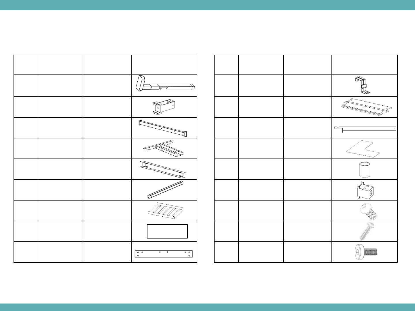
XPand Parts Used for Assembly
Item Part name Part
Description
Image
1 XP-HA-Base, leg Legs for XP-HA-
Base
2 XP-SB-Bracket Stretcher Bar
Bracket
3 XP-HA-LR-30 HA- Leg Rail, 30”
4 XP-HA-Base,
Frame support
Frame support
for HA-Base
5 XP-HA-LRC-30” Leg Rail Cover
30”
6 XP-HA-SB-XX Stretcher Bar, XX”
7 XP-CTA-XX Cable Tray
8. XP-CTC18 Cable Tray
Cover, 18”
9. XP-Link Stretcher Bar, 21”
2
Item Part name Part
Description
Image
10 XP-CTC Cable Tray Clip
11 XP-CTCXX Cable Tray
Cover, XX”
12 XP-SB-HA
HA Screen T-
Bracket
13 CCWSXXXXXX HA Work Surface
14 XP-STBP Screen T-Bracket
Sleeve
15 XP-Link-BKT HA-Link Stretcher
Bracket
16 HA-Base-Screw M6X14 Hex
screw
17 XP-Screw-WS 10-9X1 PH Pan
Head, ST P’bd
18 XP-Screw 5/16-18 x .5” Hex
Socket Cap
XPand UP – Height Adjustable- 90 Degree Station

Step 1: Prepare a large floor space to put the XPand order together. Unpack the parts and check to see if all the XPand parts are present
as per the sales order pick list.
Step 2: Assemble the HA-Leg Rail (XP-
HA-LR-30) to the Height Adjustable
Leg using (2) XP-Screws.
3
Step 3: Assemble the other end of the
Leg Rail to another Height adjustable
leg using (2) XP-Screws.
Left leg
Right leg
Step 4: Assemble (2) Stretcher Bar Bracket (XP-SB-
Brackets) to the HA-Leg Rail using (2) XP-Screws per
Bracket. Make sure the Top Face of the Bracket
faces upwards. Figure A shows the Top Face of
the Bracket.
Bracket on top/rear
indicates “Top”.
Figure A
(XP-SB-Bracket)
XPand UP – Height Adjustable- 90 Degree Station

Step 5: Assemble the Stretcher Bar (XP-SB-XX) to the
Stretcher Bar Bracket (XP-SB-Bracket) using (3) XP-Screws
per Stretcher Bar.
Step 6: Repeat Step 2 to Step 4 to build an End leg Assembly
and assemble the other end of the Stretcher Bar to the Stretcher
Bar Brackets to get a Height Adjustable Station.
4
Step 7: Using the Center hole, assemble the Link Bracket
(XP-Link-BKT) to the Leg rail using (1) XP-Screws per
Bracket.
XPand UP – Height Adjustable- 90 Degree Station

5
Step 8: Assemble the 21” Link to the Link-Bracket using (4) XP-Screws per
Bracket.
Note: While Assembling the Links make sure the Holes are facing away
from the center (as shown in the picture).
Holes on the Link should be
facing the Returns or facing away
from the center
Figure B
Step 9: Repeat Step2 to Step 7 to
build another Height Adjustable Station
with the Link-Bracket. Assemble the
other end of the 21” Link to the Link-Bkt
using (4) XP-Screws per Bracket.
XPand UP – Height Adjustable- 90 Degree Station

6
Step 10: Repeat Step 2 to Step 5 twice to build (2) Return Height
Adjustable Stations and assemble XP-SB-Bracket to the Stretcher
bars using (2) XP-Screws per Bracket.
Step 11: Assemble the XP-SB-Brackets to the 21” Link
using (2) XP-Screws per Bracket, forming a (4) Pod.
XPand UP – Height Adjustable- 90 Degree Station

7
Step 12: Slide (4) Cable Tray Clips onto each cable tray
and Snap on the assembled cable tray clips to the
Stretcher bar.
Figure C
Note: Assemble (2) XP-CTA-30 on XP-HA-SB-72 Stretcher
Bar, (2) XP-CTA-18 on XP-HA-SB-60 Stretcher Bar and (1)
CTA-18 onto the 21” Link.
Step 13: Using the screws provided with the HA-Base, assemble the
Height Adjustable Frame to the Leg.
XPand UP – Height Adjustable- 90 Degree Station

www.openplan.com | 844.OPS.OPS1 | sales@openplan.com
8
Figure D
Step 14: Place the Screen Brackets (XP-SB-HA) in flush with the (6) Leg
Rails and (2) 21” Links (as shown in the picture), do not tighten them.
Slide in the Cable Tray Covers (XP-CTCXX) over the Screen Brackets.
Secure the Cable Tray cover and Screen Bracket to the Leg Rail and
the Link using (2) XP-Screws. Slide in the Plastic Sleeves (XP-STBP) onto
the Screen Brackets.
Step 15: Slide in the Screens onto the Screen Bracket Posts.
Note: Loosen the Screws for the Screen Bracket for the Screen to
Slide in Easily.
XPand UP – Height Adjustable- 90 Degree Station

9
Step 16: Place the Work Surface (CCWSXXXXXX) on
the frame. Center the Work Surface to the Screen
and secure the Work Surface to the Frame using (12)
XP-Screw-WS per each Work Surface.
Step 17: Snap on the Leg Rail Covers (XP-HA-
LRC-30) to the Leg Rails.
Step 18: Level the HA-legs by turning the leveling
feet.
XPand UP – Height Adjustable- 90 Degree Station
Other manuals for XPAND UP
1


