OpenEmbed EdgeBox-RPI4 User manual


EdgeBox-RPI4 User Manual
www.OpenEmbed.com
3
Contents
1. Introduction....................................................................................................................................................................................... 4
1.1 Features...................................................................................................................................................................................4
1.2 Interfaces.................................................................................................................................................................................5
1.3 Block Diagram........................................................................................................................................................................7
2. Installation.........................................................................................................................................................................................8
2.1 Mounting.................................................................................................................................................................................8
2.2 Connectors and Interfaces.......................................................................................................................................................9
2.2.1 Power supply............................................................................................................................................................... 9
2.2.2 Serial Port (RS232 and RS485)...................................................................................................................................9
2.2.3 DI&DO...................................................................................................................................................................... 10
2.2.4 HDMI........................................................................................................................................................................ 11
2.2.5 Ethernet..................................................................................................................................................................... 11
2.2.6 USB HOST................................................................................................................................................................12
2.2.7 Console(USB typeC).................................................................................................................................................12
2.2.8 LED........................................................................................................................................................................... 12
2.2.9 SMA Connector
2.2.10 NANO SIM card slot...............................................................................................................................................14
2.2.11 Mini-PCIe................................................................................................................................................................ 15
2.2.12 M.2.......................................................................................................................................................................... 16
3. Drivers and Programming Interfaces.............................................................................................................................................. 17
3.1 LED.......................................................................................................................................................................................17
3.2 Serial Port (RS232 and RS485)............................................................................................................................................ 18
3.3 Cellular over Mini-PCIe....................................................................................................................................................... 18
3.4 WDT..................................................................................................................................................................................... 21
3.4.1 Block Diagram of WDT............................................................................................................................................ 21
3.4.2 How it works............................................................................................................................................................. 21
3.5 RTC.......................................................................................................................................................................................21
3.5.1.................................................................................................................................................................................... 21
3.5.2.................................................................................................................................................................................... 22
3.10 UPS for safe shut down...................................................................................................................................................... 22
4. Electrical specifications...................................................................................................................................................................24
4.1 Power consumption...............................................................................................................................................................24
4.2 UPS....................................................................................................................................................................................... 24
5. Mechanical Drawings......................................................................................................................................................................24
Downloaded from Arrow.com.Downloaded from Arrow.com.Downloaded from Arrow.com.

EdgeBox-RPI4 User Manual
www.OpenEmbed.com
4
1. Introduction
EdgeBox-RPI4 is a rugged fanless Edge Computing Controller with Raspberry Pi Computer Module 4(CM4)
for harsh industry environment.It can be used to connect the field networks with cloud or IoT applications. It is
designed from the ground up to meet the challenges of rugged applications at competitive prices,ideal for small
business or small order with scale milti-level demands.
1.1 Features
State-of-the-art Aluminium chassis for Harsh environment
Integrated passive heat sink
Built-in mini PCIe socket for RF module, such as 4G, WI-FI, Lora or Zigbee
SMA antenna holes x2
Built in UPS with supercap for safe shutdown
Encryption chip ATECC608A
Hardware Watchdog
RTC with Super Capacitor
Isolated DI&DO terminal
35mm DIN Rail support
Wide power supply from 9 to 36V DC
These features make the EdgeBox-RPI4 designed for easy setup and quick deployment for typical
industrial applications, such as status monitoring, facility management,digital signage and remote control of
public utilities.Furthermore, it is a user-friendly gateway solution with 4 cores ARM Cortex A72 and most
industry protocols can save on total deployment costs including electrical power cabling cost and help reduce
the product’s deployment time. Its ultra-lightweight and compact design is the answer for applications in
space-constricting environments ensures it can operate reliably in a variety of extreme environments
including in-vehicle applications.
Downloaded from Arrow.com.Downloaded from Arrow.com.Downloaded from Arrow.com.Downloaded from Arrow.com.
EdgeBox-RPI4 User Manual
www.OpenEmbed.com
5
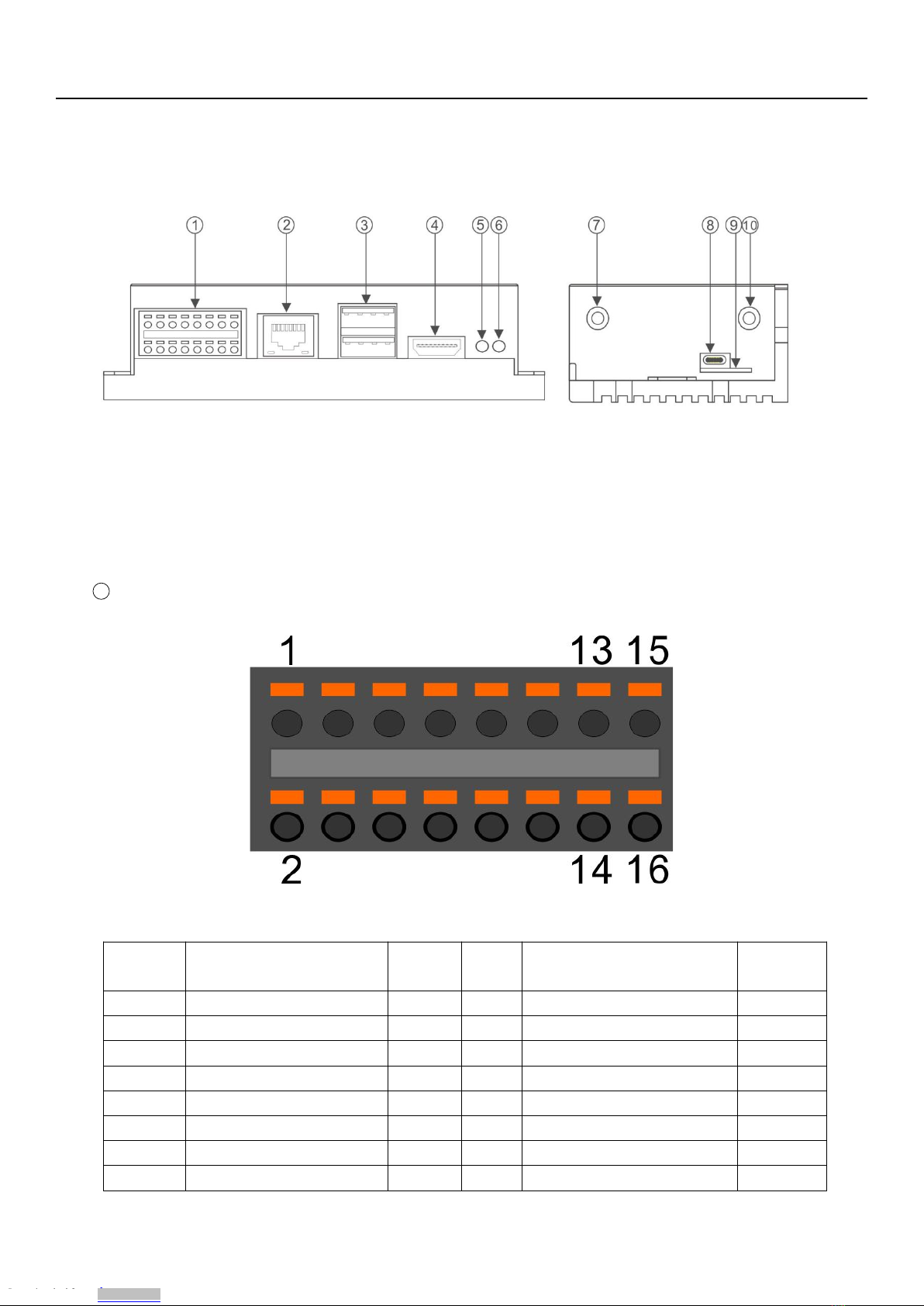
1.2 Interfaces
1Multi-Func phoenix connector
Note Func name PIN # PIN# Func name Note
POWER 1 2 GND
RS485_A 3 4 RS232_RX
RS485_B 5 6 RS232_TX
RS485_GND 7 8 RS232_GND
DI0- 9 10 DO0_0
DI0+ 11 12 DO0_1
DI1- 13 14 DO1_0
DI1+ 15 16 DO1_1
Downloaded from Arrow.com.Downloaded from Arrow.com.Downloaded from Arrow.com.Downloaded from Arrow.com.Downloaded from Arrow.com.

EdgeBox-RPI4 User Manual
www.OpenEmbed.com
6
NOTE: 24awg to 16awg cable are suggested
2Ethernet connector
3USB 2.0 x 2
4HDMI
5LED2
6LED1
7SMA antenna 1
8Console(USB type C)
9SIM card slot
10 SMA antenna 2
Downloaded from Arrow.com.Downloaded from Arrow.com.Downloaded from Arrow.com.Downloaded from Arrow.com.Downloaded from Arrow.com.Downloaded from Arrow.com.
EdgeBox-RPI4 User Manual
www.OpenEmbed.com
7
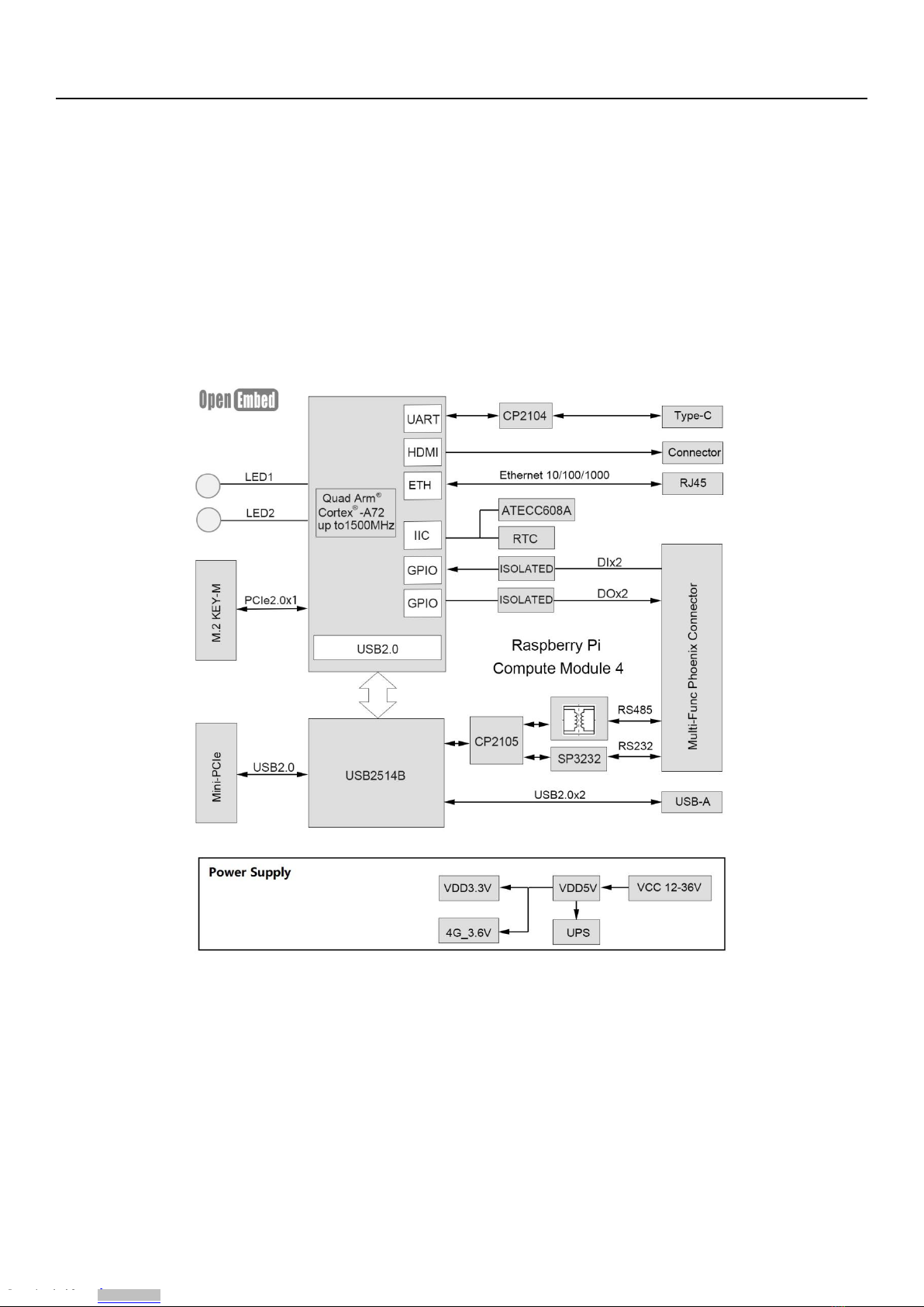
1.3 Block Diagram
The processing core of the EdgeBox-RPI4 is a Raspberry CM4 board. A OpenEmbed specific base
board implements the specific features. Refer to next figure for the block diagram.
Downloaded from Arrow.com.Downloaded from Arrow.com.Downloaded from Arrow.com.Downloaded from Arrow.com.Downloaded from Arrow.com.Downloaded from Arrow.com.Downloaded from Arrow.com.
EdgeBox-RPI4 User Manual
www.OpenEmbed.com
8
2. Installation
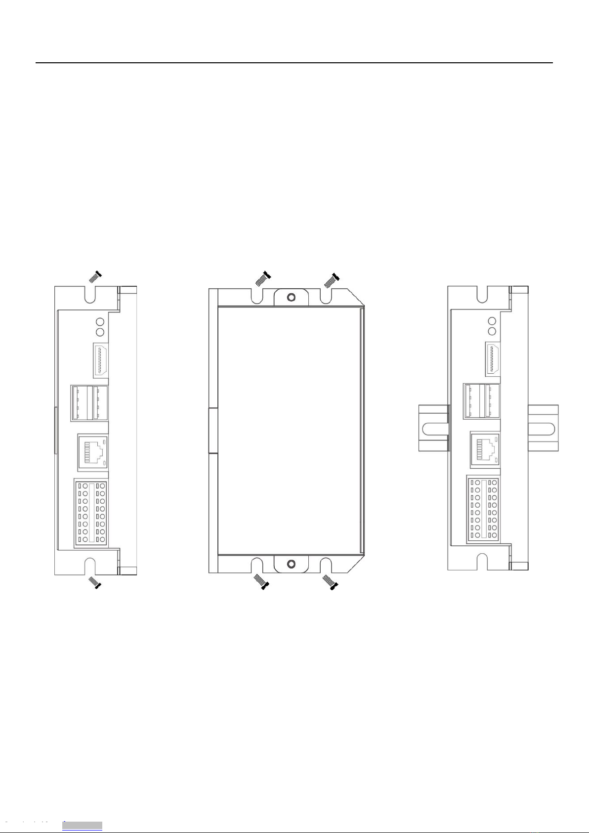
2.1 Mounting
The EdgeBox-RPI4 is intended for two wall mounts, as well one with 35mm DIN-rail . Refer to next figure
for the recommended mounting orientation.
Downloaded from Arrow.com.Downloaded from Arrow.com.Downloaded from Arrow.com.Downloaded from Arrow.com.Downloaded from Arrow.com.Downloaded from Arrow.com.Downloaded from Arrow.com.Downloaded from Arrow.com.

EdgeBox-RPI4 User Manual
www.OpenEmbed.com
9
2.2 Connectors and Interfaces
2.2.1 Power supply
Pin# Signal Description
1 POWER_IN DC 9-36V
2 GND Ground (Reference potential)
The PE signal is optional. If there is no EMI present ,the PE connection can left open.
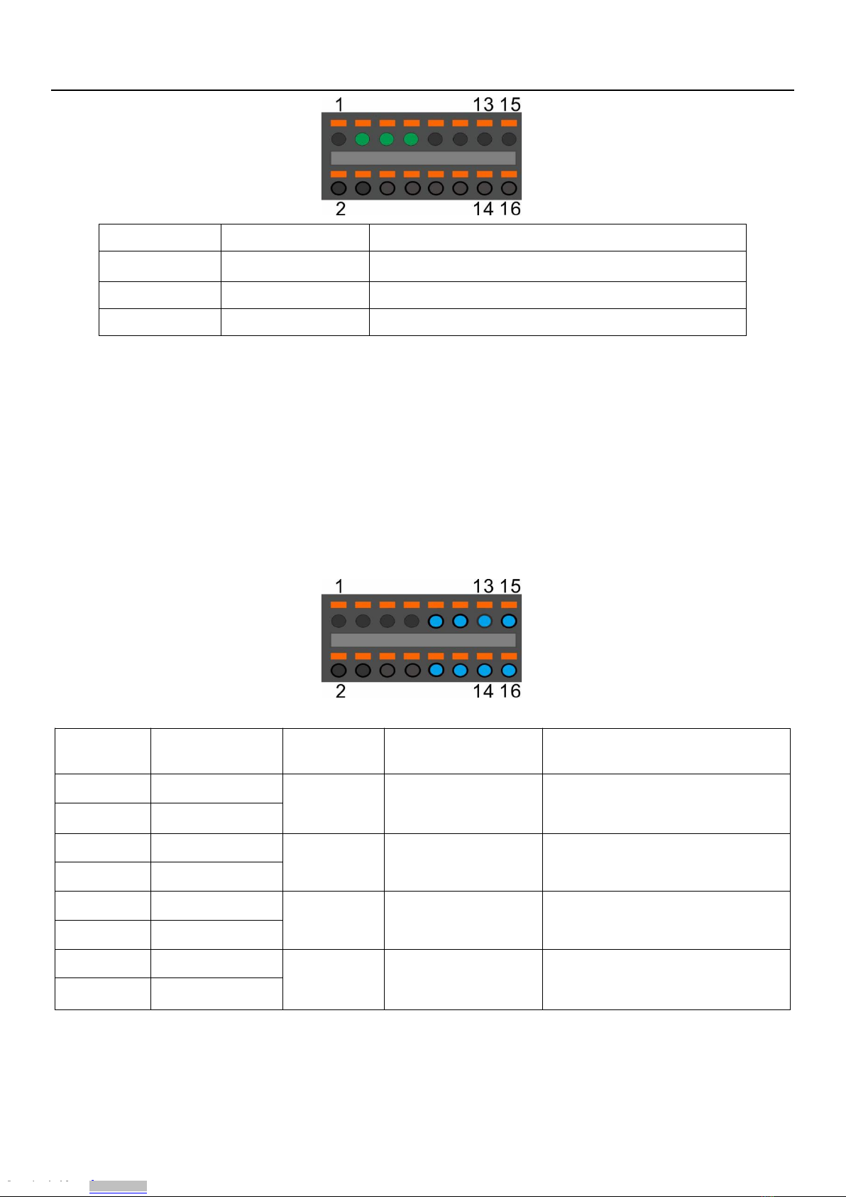
2.2.2 Serial Port (RS232 and RS485)
Pin# Signal Description
4 RS232_RX RS232 receive line
6 RS232_TX RS232 transmit line
8 GND Ground (Reference potential)
Downloaded from Arrow.com.Downloaded from Arrow.com.Downloaded from Arrow.com.Downloaded from Arrow.com.Downloaded from Arrow.com.Downloaded from Arrow.com.Downloaded from Arrow.com.Downloaded from Arrow.com.Downloaded from Arrow.com.
EdgeBox-RPI4 User Manual
www.OpenEmbed.com
10
Pin# Signal Description
3 RS485_A RS485 difference line high
5 RS485_B RS485 difference line low
7 RS485 _GND RS485 Ground (isolated from GND)
The RS485_GND signal is isolated with “GND” signal. If a shielded twisted pair wire is used ,the RS485
_GND is connected to the shield.
NOTE:The 120 Ohm termination resistor for RS485 has been installed inside.
2.2.3 DI&DO
Pin# Signal of
terminal
PIN Level of
active
PIN of GPIO from
BCM2711
NOTE
09 DI0-
HIGH GPIO17
11 DI0+
13 DI1- HIGH GPIO27
15 DI1+
10 DO0_0 HIGH GPIO23
12 DO0_1
14 DO1_0
HIGH GPIO24
16 DO1_1
NOTE:
Downloaded from Arrow.com.Downloaded from Arrow.com.Downloaded from Arrow.com.Downloaded from Arrow.com.Downloaded from Arrow.com.Downloaded from Arrow.com.Downloaded from Arrow.com.Downloaded from Arrow.com.Downloaded from Arrow.com.Downloaded from Arrow.com.
Table of contents


