manuals.online logo
Brands
  1. Home
  2. •
  3. Brands
  4. •
  5. Opitec
  6. •
  7. Amplifier
  8. •
  9. Opitec 111.677 User manual

Opitec 111.677 User manual

1
D111677#1
111.677
PARTS LIST
Code
Circuit board 1
Capacitor 1 μF 105 1
Capacitor 470 nF 474 1
Capacitor 100nF 104 1
Capcitor 220 μF 1
Resistor 100 kOhm 1
Micro switch 1
Small scews 4
Modelling plywood 70x50x1,5 1
IC holder 8-plg. 1
IC TDA 7052 1
Black wire 1
Battery clip 1
Amplifier for MP3 Louds-
peaker
Necessary tools
Solderng iron,solder
Fretsaw
Drill ø 3mm
All purpose glue
Wire strippers
Please Note
The OPITEC range of projects is not intended as play
toys for young children.They are teaching aids for
young people learning the skills of Craft, Design and
Technolo- gy.These projects should only be undertak-
en and tested with the guidance of a fully qualified
adult. The finished projects are not suitable to give to
children under 3 years old. Some parts can be swal-
lowed. Dan- ger of suffocation!
2D111677#1
1
2
3
4
8
7
6
5
+L+ L-
-
100kOhm
470 nF
Input +
220 uF
100 nF 1 uF
Input
208235
1 uF
100 nF
100 kOhm
6
3
470 nF
2
Input 1 +
TDA7052A 4
220 uF
-
+
5
L-
L+
8
1
INSTRUCTIONS
Now add the capacitor 100 nF (Code 104) and the 1 uF Kondensator (Code 105) in the marked places on the board.
Insert the resistor 100 kOhm in the holes in the top of the board and solder it to the tracks underneath.
Next insert the capacitor 220 uF, here the polarity must be noted. It must be inserted the correct way around note the plus and
minus legs. Solder in place underneath!
Check all the capacitors once more , especially the polarity if necessary ,then trim the extra length form the legs underneath
the board
Solder the red battery cable to the plus connection and the black cable to the minus connection on the board.
Die IC holder, is inserted in the top of the board the correct way around and the legs are soldered to the tracks on the bottom
of the board.
NOTE: The IC holder has a notch at one end. This must correspond
with the diagram on the top of the board
The amplier IC is inserted in the holder once all the other components have been soldered in place to ensure that is not
damaged during the soldering
Insert the 470 nF ceramic capacitor (Code 474) from above. Bend the legs slighty apart underneath the board an solder them
to the tracks.
1. Constructing the circuit board
The circuit board has two dierent sides. The top side is drilled and printed showing the positions of the components. The
bottom has all the tracks where the components are soldered
Schematic diagram
3
D111677#1
85 85
12
50
70
5
10
12,5
25
30
10 12
Ø 3
85 85
12
50
70
5
10
12,5
25
30
10 12
Ø 3
1
2
3
4
8
7
6
5
+L+ L-
-
100kOhm
470 nF
Input +
220 uF
100 nF 1 uF
Input
208235
+- +-
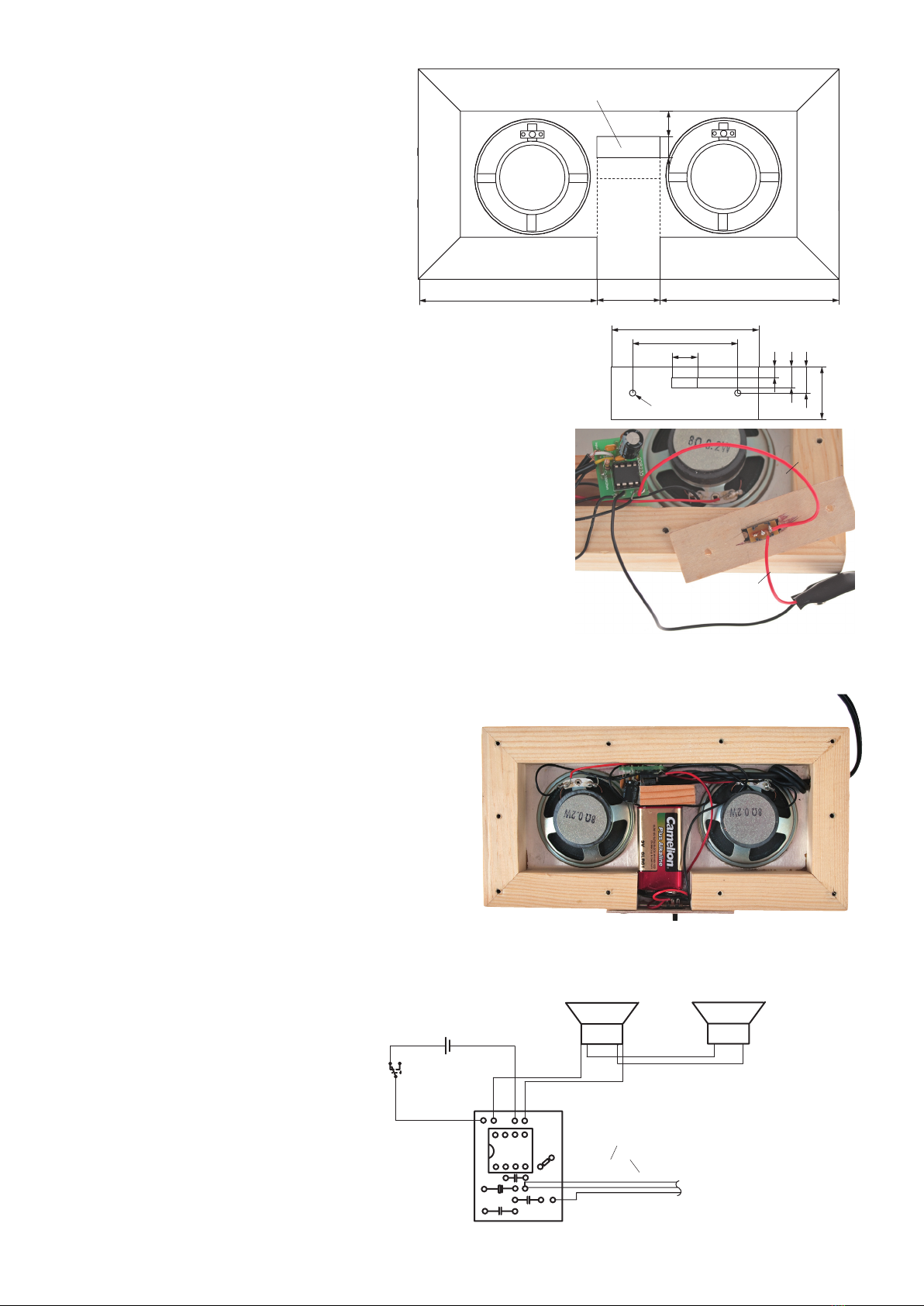
3. Before mounting the loudspeakers measure out
and saw the the pine side strips and the middle
piece (30mm)
Measure and saw out the middle remainder piece
ca. 10x20x30 and glue it in place as shown.
Remainder
Wiring plan
4. Measure and saw out the plywood piece 25x70mm and sand the edges.
Measure and cut out the slot for the switch as shown. To do this drill a
hole in the slot for a fretsaw blade to pass through and the saw out the
shape.Sand the edges drill the 3mm holes
5. Insert the switch in the slot and glue it in place. Divide up the red cable
from the battery clip, so that the cable to the circuit board is ca 100mm
and the cable on the connector is 40mm long. Take the ca. 100mm red
cable and soder it to the circuit board (+) and solder it to the outer con-
nection on the switch and the short red to the middle connection on the
switch. See citcuit diagram.
7. Connect a 9V- Block battery with the battery clip and place it
as shown. Insert the circuit board carefully between the outer
and and the middle piece.
Mount the plywood piece with the switch and x it in position
with screws!
Finished!
2. Mounting the loudspeakers:
6. Take the connection cable from the MP3 player.Connect (solder ) it to the
input on the circuit board as shown overleaf. The ends of the two cables
are twisted together and soldered to plus + input connection on the
circuit board
see circuit diagrams. The 3rd uninsulated cable should be shortened to
20mm and soldered to a circuit board input
Connect with a cable L+ and L- (Circuit board) with a loudspeaker. Then as
as already stated, make a connection from loudspeaker + to loudspeaker
+ and loudspeaker minus to loudspeaker minus
Battery clip
Micro switch
Loudspeaker
Loudspeaker connection cable
Coloured cable +
+-
Copper cable
100mm
40mm
40mm
100mm
Please note !
If the components are soldered in
the wrong place it can lead to the
destruction of the circuit or any
device that it is connected to !

Popular Amplifier manuals by other brands

Leviton 47692-ESM installation instructions

Leviton

Leviton 47692-ESM installation instructions

NuTone Direct-A-Com Series 3 470 Service manual

NuTone

NuTone Direct-A-Com Series 3 470 Service manual

QSC DPA-Q quick start guide

QSC

QSC DPA-Q quick start guide

Pioneer GM-D8601 owner's manual

Pioneer

Pioneer GM-D8601 owner's manual

Yamaha A-S801 owner's manual

Yamaha

Yamaha A-S801 owner's manual

TECshow DOME CORE 240 user manual

TECshow

TECshow DOME CORE 240 user manual

Audio Research VS115 owner's manual

Audio Research

Audio Research VS115 owner's manual

Episode ECA-70AMP-2D-150A installation manual

Episode

Episode ECA-70AMP-2D-150A installation manual

SG Micro SGM4700 manual

SG Micro

SG Micro SGM4700 manual

Rotel RC-970BX owner's manual

Rotel

Rotel RC-970BX owner's manual

Lindell Audio LiN76 manual

Lindell Audio

Lindell Audio LiN76 manual

Crest Audio MULTIPLEX 900 Specifications

Crest Audio

Crest Audio MULTIPLEX 900 Specifications

Monacor PA-702 instruction manual

Monacor

Monacor PA-702 instruction manual

AudioBahn ACAP651N operating instructions

AudioBahn

AudioBahn ACAP651N operating instructions

Ashly SRA-2075 Specification sheet

Ashly

Ashly SRA-2075 Specification sheet

Eletronika AUTV/1500LD user manual

Eletronika

Eletronika AUTV/1500LD user manual

True PRECISION 8 Operation manual

True

True PRECISION 8 Operation manual

Triad RackAmp DSP v2 quick start guide

Triad

Triad RackAmp DSP v2 quick start guide

manuals.online logo
manuals.online logoBrands
  • About & Mission
  • Contact us
  • Privacy Policy
  • Terms and Conditions

Copyright 2025 Manuals.Online. All Rights Reserved.